Page 1370 of 2870
FU(H4DOTC)-15
FUEL INJECTION (FUEL SYSTEM)
Intake Manifold
(6) Place the power steering pump on right side
wheel apron.
13) Disconnect the emission hose from PCV valve.
14) Disconnect the engine coolant hoses from
throttle body.
15) Disconnect the brake booster hose.16) Disconnect the pressure hose from intake duct.
17) Disconnect the engine harness connectors
from bulkhead harness connectors.
18) Disconnect the connectors from the engine
coolant temperature sensor (A), oil pressure switch
(B) and crankshaft position sensor (C).
FU-00021
FU-00022
FU-00012
FU-00023
FU-00024
FU-00025
FU-02086
(A)
(B)
(C)
FU-00027
Page 1371 of 2870
FU(H4DOTC)-16
FUEL INJECTION (FUEL SYSTEM)
Intake Manifold
19) Disconnect the knock sensor connector.
20) Disconnect the connector from crankshaft posi-
tion sensor.
21) Disconnect the connector from camshaft posi-
tion sensor.
22) Disconnect the connector from AVCS camshaft
position sensor.23) Disconnect the connector from oil flow control
solenoid valve.
24) Disconnect the connector from ignition coil.
25) Disconnect the engine harness fixed by clip (A)
from bracket.
FU-00028
FU-00029
FU-00059
FU-00061
ME-00711
FU-00030
FU-00031
(A)
Page 1373 of 2870
FU(H4DOTC)-18
FUEL INJECTION (FUEL SYSTEM)
Intake Manifold
4) Connect the connector to the oil pressure switch
(B), crankshaft position sensor (C) and engine
coolant temperature sensor (A).
5) Connect the connector to knock sensor.
6) Connect the connector to crankshaft position
sensor.
7) Connect the connector to camshaft position sen-
sor.8) Connect the connector to AVCS camshaft posi-
tion sensor.
9) Connect the connector to oil flow control sole-
noid valve.
10) Connect the connector to ignition coil.
11) Connect the engine harness with clip (A) to the
bracket.
(A)
(B)
(C)
FU-00027
FU-00028
FU-00029
FU-00059
FU-00061
ME-00711
FU-00030
FU-00031
(A)
Page 1444 of 2870
IN(H4DOTC)-5
INTAKE (INDUCTION)
General Description
4. TURBOCHARGER
(1) Oil inlet pipe (7) GasketTightening torque: N⋅m (kgf-m, ft-lb)
(2) Metal gasket (8) Oil outlet pipeT1: 4.4 (0.45, 3.3)
(3) Turbocharger (9) ClipT2: 4.9 (0.50, 3.6)
(4) Water pipe (10) Oil outlet hoseT3: 29 (3.0, 21.7)
(5) Clamp (11) Turbocharger bracket RHT4: 33 (3.4, 24.6)
(6) Engine coolant hose (12) Turbocharger bracket LHT5: 16 (1.6, 11.6)
IN-00249
T5
T1(3)
(8)
(4) (5) (9)
(9)(6)
(12) (1)
(2)
(2)
(2)
(2)
(2)
(7)
(2)
(11)(10)
T4
T2
T3
T4
(2)
Page 1451 of 2870
IN(H4DOTC)-12
INTAKE (INDUCTION)
Turbocharger
6. Turbocharger
A: REMOVAL
1) Set the vehicle on a lift.
2) Disconnect the ground cable from battery.
3) Remove the center exhaust pipe.
EX(H4DOTC)-9, REMOVAL, Center Exhaust
Pipe.>
4) Lower the vehicle.
5) Separate the turbocharger joint pipe from turbo-
charger.
6) Disconnect the engine coolant hose which is
connected to coolant filler tank.7) Loosen the clamp which secures turbocharger to
intake duct.
8) Remove the bolt which secures bracket of oil
pipe to turbocharger.
9) Remove the oil pipe from turbocharger.
10) Remove the turbocharger bracket.
11) Disconnect the oil outlet hose from pipe.
12) Take out the turbocharger from engine com-
partment.
FU-00009
IN-00019
IN-00020IN-00074
IN-00022
IN-00023
IN-00024
Page 1452 of 2870
IN(H4DOTC)-13
INTAKE (INDUCTION)
Turbocharger
B: INSTALLATION
1) Connect the oil outlet hose to outlet pipe.
2) Install the turbocharger to intake duct.
Tightening torque:
3 N
⋅m (0.3 kgf-m, 2.2 ft-lb)
3) Install the oil pipe to turbocharger.
Tightening torque:
16 N
⋅m (1.6 kgf-m, 11.6 ft-lb)
4) Install the joint pipe to turbocharger.
NOTE:
Replace the gasket with a new one.Tightening torque:
35 N
⋅m (3.6 kgf-m, 26.0 ft-lb)
5) Install the turbocharger bracket.
Tightening torque:
33 N
⋅m (3.4 kgf-m, 24.6 ft-lb)
6) Connect the engine coolant hose which is con-
nected to coolant filler tank.
7) Lift-up the vehicle.
8) Install the center exhaust pipe.
EX(H4DOTC)-10, INSTALLATION, Center Ex-
haust Pipe.>
IN-00024
IN-00074
IN-00022
IN-00019
IN-00023
IN-00020
Page 1457 of 2870

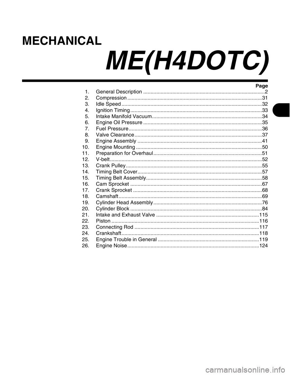
MECHANICAL
ME(H4DOTC)
Page
1. General Description ....................................................................................2
2. Compression .............................................................................................31
3. Idle Speed .................................................................................................32
4. Ignition Timing ...........................................................................................33
5. Intake Manifold Vacuum............................................................................34
6. Engine Oil Pressure ..................................................................................35
7. Fuel Pressure ............................................................................................36
8. Valve Clearance ........................................................................................37
9. Engine Assembly ......................................................................................41
10. Engine Mounting .......................................................................................50
11. Preparation for Overhaul ...........................................................................51
12. V-belt .........................................................................................................52
13. Crank Pulley ..............................................................................................55
14. Timing Belt Cover......................................................................................57
15. Timing Belt Assembly................................................................................58
16. Cam Sprocket ...........................................................................................67
17. Crank Sprocket .........................................................................................68
18. Camshaft ...................................................................................................69
19. Cylinder Head Assembly ...........................................................................76
20. Cylinder Block ...........................................................................................84
21. Intake and Exhaust Valve .......................................................................115
22. Piston ......................................................................................................116
23. Connecting Rod ......................................................................................117
24. Crankshaft ...............................................................................................118
25. Engine Trouble in General ......................................................................119
26. Engine Noise ...........................................................................................124
Page 1458 of 2870

ME(H4DOTC)-2
MECHANICAL
General Description
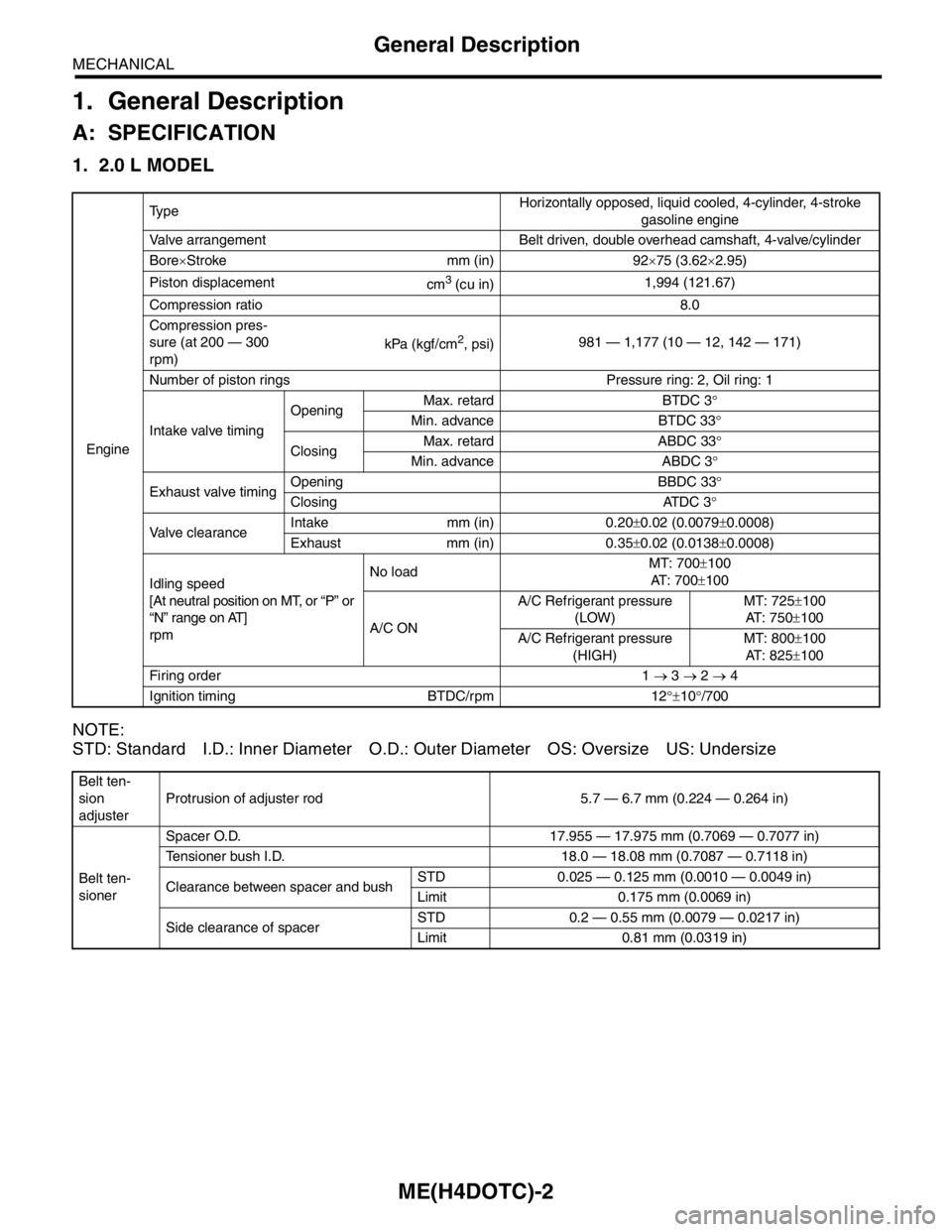
1. General Description
A: SPECIFICATION
1. 2.0 L MODEL
NOTE:
STD: Standard I.D.: Inner Diameter O.D.: Outer Diameter OS: Oversize US: Undersize
EngineTy p eHorizontally opposed, liquid cooled, 4-cylinder, 4-stroke
gasoline engine
Valve arrangement Belt driven, double overhead camshaft, 4-valve/cylinder
Bore×Stroke mm (in) 92×75 (3.62×2.95)
Piston displacement
cm
3 (cu in)1,994 (121.67)
Compression ratio 8.0
Compression pres-
sure (at 200 — 300
rpm)kPa (kgf/cm
2, psi)981 — 1,177 (10 — 12, 142 — 171)
Number of piston rings Pressure ring: 2, Oil ring: 1
Intake valve timingOpeningMax. retard BTDC 3°
Min. advance BTDC 33°
ClosingMax. retard ABDC 33°
Min. advance ABDC 3°
Exhaust valve timingOpening BBDC 33°
Closing ATDC 3°
Valve clearanceIntake mm (in) 0.20±0.02 (0.0079±0.0008)
Exhaust mm (in) 0.35±0.02 (0.0138±0.0008)
Idling speed
[At neutral position on MT, or “P” or
“N” range on AT]
rpmNo loadMT: 700±100
AT : 7 0 0±100
A/C ONA/C Refrigerant pressure
(LOW)MT: 725±100
AT : 7 5 0±100
A/C Refrigerant pressure
(HIGH)MT: 800±100
AT : 8 2 5±100
Firing order 1 → 3 → 2 → 4
Ignition timing BTDC/rpm 12°±10°/700
Belt ten-
sion
adjusterProtrusion of adjuster rod 5.7 — 6.7 mm (0.224 — 0.264 in)
Belt ten-
sionerSpacer O.D. 17.955 — 17.975 mm (0.7069 — 0.7077 in)
Tensioner bush I.D. 18.0 — 18.08 mm (0.7087 — 0.7118 in)
Clearance between spacer and bushSTD 0.025 — 0.125 mm (0.0010 — 0.0049 in)
Limit 0.175 mm (0.0069 in)
Side clearance of spacerSTD 0.2 — 0.55 mm (0.0079 — 0.0217 in)
Limit 0.81 mm (0.0319 in)