2004 SUBARU FORESTER window
[x] Cancel search: windowPage 729 of 2870
PI-6
PRE-DELIVERY INSPECTION
Pre-delivery Inspection
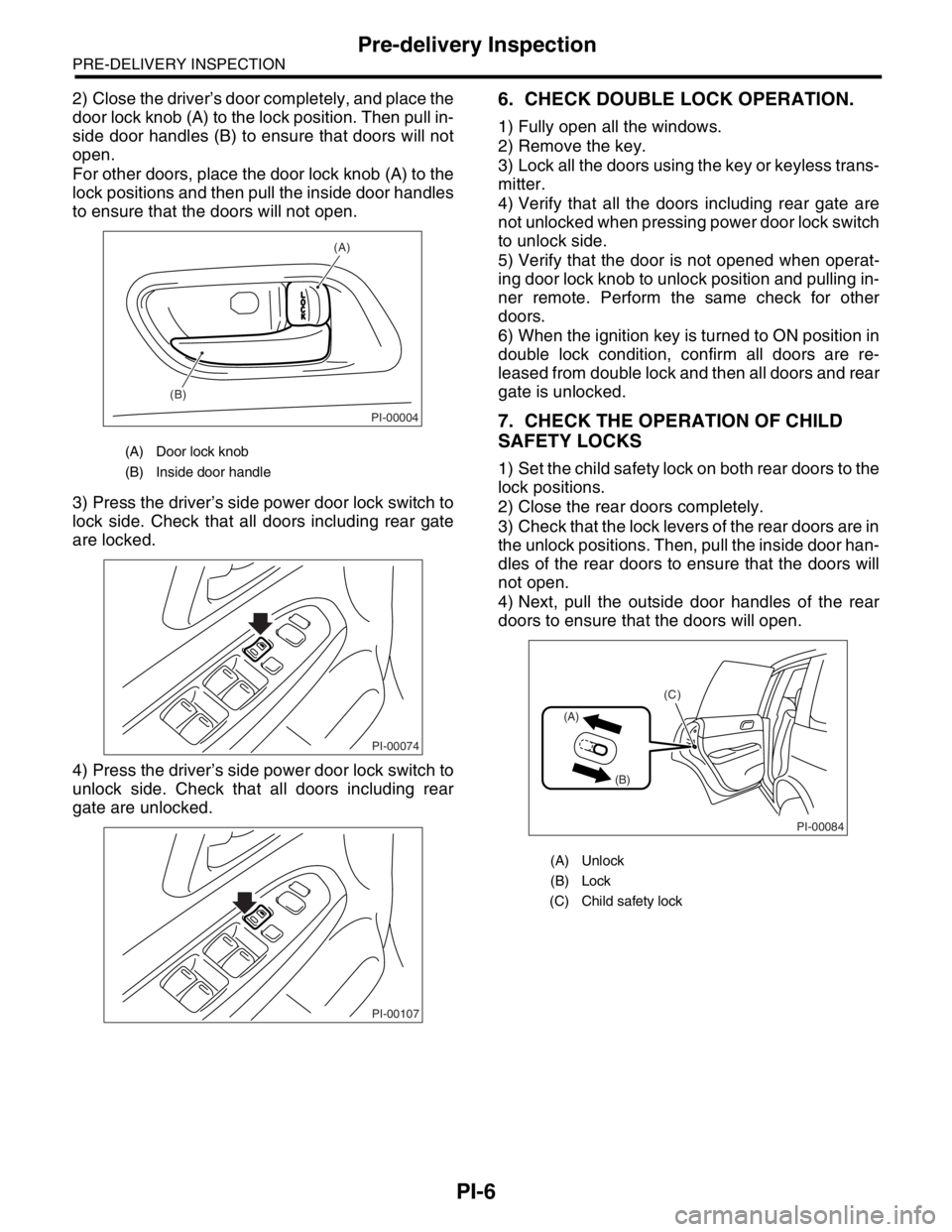
2) Close the driver’s door completely, and place the
door lock knob (A) to the lock position. Then pull in-
side door handles (B) to ensure that doors will not
open.
For other doors, place the door lock knob (A) to the
lock positions and then pull the inside door handles
to ensure that the doors will not open.
3) Press the driver’s side power door lock switch to
lock side. Check that all doors including rear gate
are locked.
4) Press the driver’s side power door lock switch to
unlock side. Check that all doors including rear
gate are unlocked.6. CHECK DOUBLE LOCK OPERATION.
1) Fully open all the windows.
2) Remove the key.
3) Lock all the doors using the key or keyless trans-
mitter.
4) Verify that all the doors including rear gate are
not unlocked when pressing power door lock switch
to unlock side.
5) Verify that the door is not opened when operat-
ing door lock knob to unlock position and pulling in-
ner remote. Perform the same check for other
doors.
6) When the ignition key is turned to ON position in
double lock condition, confirm all doors are re-
leased from double lock and then all doors and rear
gate is unlocked.
7. CHECK THE OPERATION OF CHILD
SAFETY LOCKS
1) Set the child safety lock on both rear doors to the
lock positions.
2) Close the rear doors completely.
3) Check that the lock levers of the rear doors are in
the unlock positions. Then, pull the inside door han-
dles of the rear doors to ensure that the doors will
not open.
4) Next, pull the outside door handles of the rear
doors to ensure that the doors will open.
(A) Door lock knob
(B) Inside door handle
PI-00004
(A)
(B)
PI-00074
PI-00107
(A) Unlock
(B) Lock
(C) Child safety lock
PI-00084
(A)
(B)
(C)
Page 732 of 2870
PI-9
PRE-DELIVERY INSPECTION
Pre-delivery Inspection
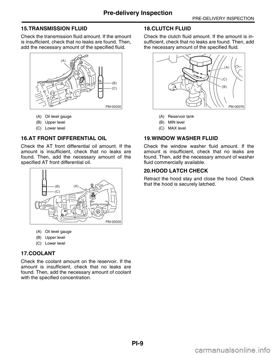
15.TRANSMISSION FLUID
Check the transmission fluid amount. If the amount
is insufficient, check that no leaks are found. Then,
add the necessary amount of the specified fluid.
16.AT FRONT DIFFERENTIAL OIL
Check the AT front differential oil amount. If the
amount is insufficient, check that no leaks are
found. Then, add the necessary amount of the
specified AT front differential oil.
17.COOLANT
Check the coolant amount on the reservoir. If the
amount is insufficient, check that no leaks are
found. Then, add the necessary amount of coolant
with the specified concentration.
18.CLUTCH FLUID
Check the clutch fluid amount. If the amount is in-
sufficient, check that no leaks are found. Then, add
the necessary amount of the specified fluid.
19.WINDOW WASHER FLUID
Check the window washer fluid amount. If the
amount is insufficient, check that no leaks are
found. Then, add the necessary amount of washer
fluid commercially available.
20.HOOD LATCH CHECK
Retract the hood stay and close the hood. Check
that the hood is securely latched.
(A) Oil level gauge
(B) Upper level
(C) Lower level
(A) Oil level gauge
(B) Upper level
(C) Lower level
PM-00030
(B)
(C) (A)
PM-00035
(B)
(C)(A)
(A) Reservoir tank
(B) MIN level
(C) MAX level
PM-00076
(A)
(B) (C)
Page 733 of 2870
PI-10
PRE-DELIVERY INSPECTION
Pre-delivery Inspection
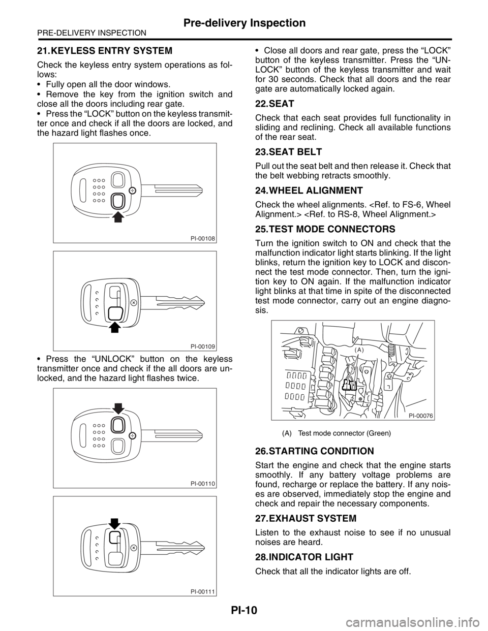
21.KEYLESS ENTRY SYSTEM
Check the keyless entry system operations as fol-
lows:
Fully open all the door windows.
Remove the key from the ignition switch and
close all the doors including rear gate.
Press the “LOCK” button on the keyless transmit-
ter once and check if all the doors are locked, and
the hazard light flashes once.
Press the “UNLOCK” button on the keyless
transmitter once and check if the all doors are un-
locked, and the hazard light flashes twice. Close all doors and rear gate, press the “LOCK”
button of the keyless transmitter. Press the “UN-
LOCK” button of the keyless transmitter and wait
for 30 seconds. Check that all doors and the rear
gate are automatically locked again.
22.SEAT
Check that each seat provides full functionality in
sliding and reclining. Check all available functions
of the rear seat.
23.SEAT BELT
Pull out the seat belt and then release it. Check that
the belt webbing retracts smoothly.
24.WHEEL ALIGNMENT
Check the wheel alignments.
25.TEST MODE CONNECTORS
Turn the ignition switch to ON and check that the
malfunction indicator light starts blinking. If the light
blinks, return the ignition key to LOCK and discon-
nect the test mode connector. Then, turn the igni-
tion key to ON again. If the malfunction indicator
light blinks at that time in spite of the disconnected
test mode connector, carry out an engine diagno-
sis.
26.STARTING CONDITION
Start the engine and check that the engine starts
smoothly. If any battery voltage problems are
found, recharge or replace the battery. If any nois-
es are observed, immediately stop the engine and
check and repair the necessary components.
27.EXHAUST SYSTEM
Listen to the exhaust noise to see if no unusual
noises are heard.
28.INDICATOR LIGHT
Check that all the indicator lights are off.
PI-00108
PI-00109
PI-00110
PI-00111
(A) Test mode connector (Green)
PI-00076
(A)
Page 734 of 2870
PI-11
PRE-DELIVERY INSPECTION
Pre-delivery Inspection
29.CLOCK
Check the clock for normal operations and enough
accuracy.
30.RADIO
Check the radio for full functionality and normal
noise level. Also check the CD unit operations.
31.FRONT ACCESSORY POWER SUPPLY
SOCKET
Check the front accessory power supply socket op-
erations.
32.LIGHTING SYSTEM
Check the headlight operations.
Check the brake light operations.
Check the other lights for normal operations.
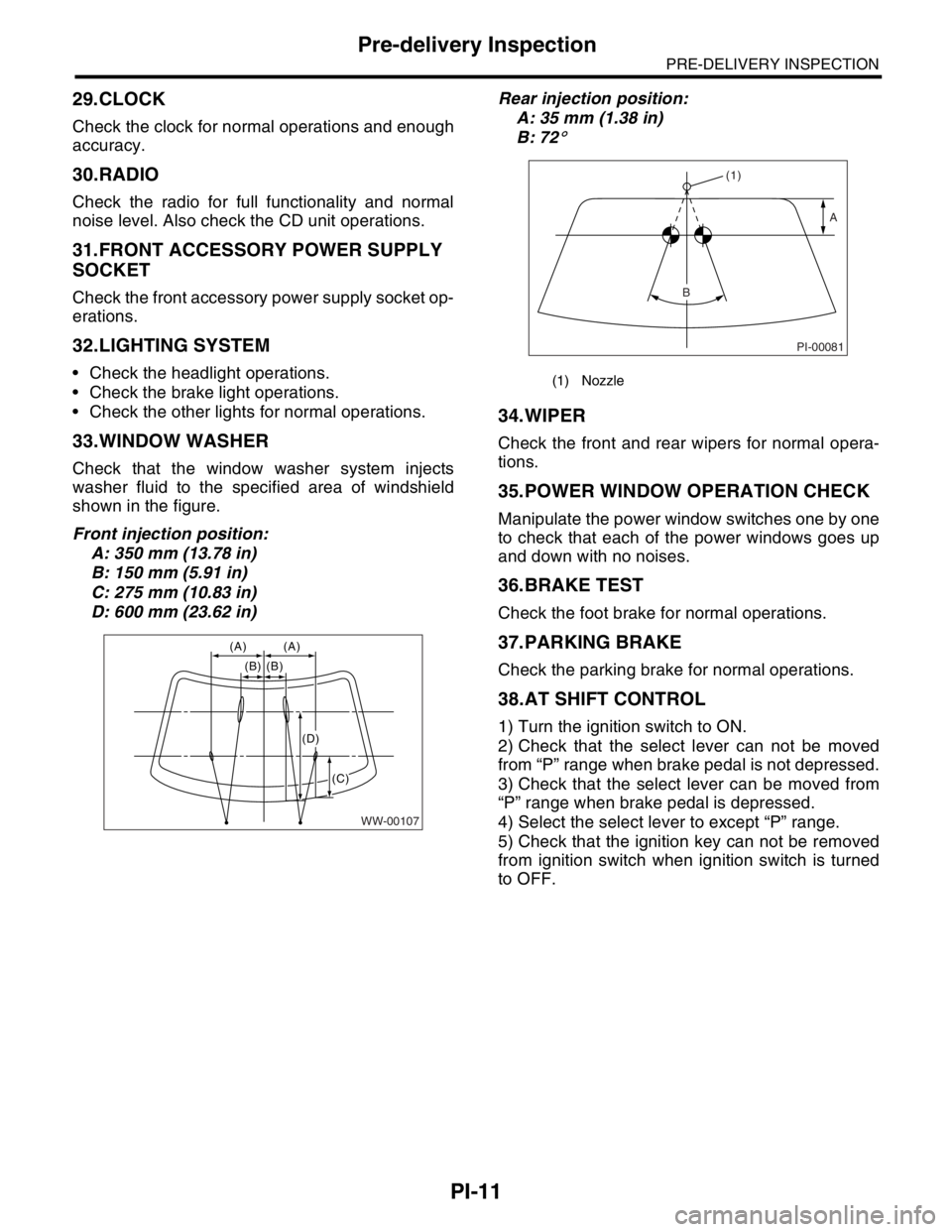
33.WINDOW WASHER
Check that the window washer system injects
washer fluid to the specified area of windshield
shown in the figure.
Front injection position:
A: 350 mm (13.78 in)
B: 150 mm (5.91 in)
C: 275 mm (10.83 in)
D: 600 mm (23.62 in)Rear injection position:
A: 35 mm (1.38 in)
B: 72
°
34.WIPER
Check the front and rear wipers for normal opera-
tions.
35.POWER WINDOW OPERATION CHECK
Manipulate the power window switches one by one
to check that each of the power windows goes up
and down with no noises.
36.BRAKE TEST
Check the foot brake for normal operations.
37.PARKING BRAKE
Check the parking brake for normal operations.
38.AT SHIFT CONTROL
1) Turn the ignition switch to ON.
2) Check that the select lever can not be moved
from “P” range when brake pedal is not depressed.
3) Check that the select lever can be moved from
“P” range when brake pedal is depressed.
4) Select the select lever to except “P” range.
5) Check that the ignition key can not be removed
from ignition switch when ignition switch is turned
to OFF.
WW-00107
(A) (A)
(B) (B)
(C)
(D)
(1) Nozzle
PI-00081
(1)
A
B
Page 735 of 2870
PI-12
PRE-DELIVERY INSPECTION
Pre-delivery Inspection
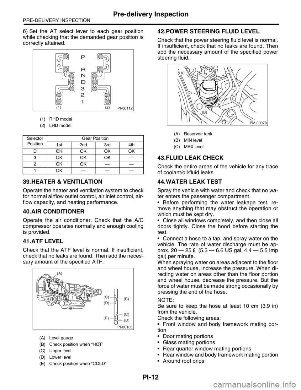
6) Set the AT select lever to each gear position
while checking that the demanded gear position is
correctly attained.
39.HEATER & VENTILATION
Operate the heater and ventilation system to check
for normal airflow outlet control, air inlet control, air-
flow capacity, and heating performance.
40.AIR CONDITIONER
Operate the air conditioner. Check that the A/C
compressor operates normally and enough cooling
is provided.
41.ATF LEVEL
Check that the ATF level is normal. If insufficient,
check that no leaks are found. Then add the neces-
sary amount of the specified ATF.
42.POWER STEERING FLUID LEVEL
Check that the power steering fluid level is normal.
If insufficient, check that no leaks are found. Then
add the necessary amount of the specified power
steering fluid.
43.FLUID LEAK CHECK
Check the entire areas of the vehicle for any trace
of coolant/oil/fluid leaks.
44.WATER LEAK TEST
Spray the vehicle with water and check that no wa-
ter enters the passenger compartment.
Before performing the water leakage test, re-
move anything that may obstruct the operation or
which must be kept dry.
Close all windows completely, and then close all
doors tightly. Close the hood before starting the
test.
Connect a hose to a tap, and spray water on the
vehicle. The rate of water discharge must be ap-
prox. 20 — 252 (5.3 — 6.6 US gal, 4.4 — 5.5 Imp
gal) per minute.
When spraying water on areas adjacent to the floor
and wheel house, increase the pressure. When di-
recting water on areas other than the floor portion
and wheel house, decrease the pressure. But the
force of water must be made strong occasionally by
pressing the end of the hose.
NOTE:
Be sure to keep the hose at least 10 cm (3.9 in)
from the vehicle.
Check the following areas:
Front window and body framework mating por-
tion
Door mating portions
Glass mating portions
Rear quarter window mating portions
Rear window and body framework mating portion
Around roof drips
(1) RHD model
(2) LHD model
Selector
Po si t io nGear Position
1st 2nd 3rd 4th
D OKOKOKOK
3 OKOKOK —
2OKOK——
1OK———
(A) Level gauge
(B) Check position when “HOT”
(C) Upper level
(D) Lower level
(E) Check position when “COLD”
PI-00112(1) (2)
P
R
N
D
3
2
1
PI-00105
COLD
LFHOT LF
(A)
(C)
(D)
(C)
(D)
(E)
(B)
(A) Reservoir tank
(B) MIN level
(C) MAX level
PM-00070
(A)
(C)
(B)
Page 736 of 2870

PI-13
PRE-DELIVERY INSPECTION
Pre-delivery Inspection
If any dampness in the compartment is discovered
after the water has been applied, carefully check all
areas that may have possibly contributed to the
leak.
45.APPEARANCE CHECK 2
1) When vehicle body is covered with protective
film (wrap guard), peel it off.
NOTE:
Use of steam eases peeling off the wrap guard.
When performing on the vehicles left for a long
time, or during low temperature period, sprinkle
some water heated to 50 — 60°C (122 — 140°F)
over the vehicle to raise its surface temperature be-
fore peeling off the wrap guard.
Do not use the water heated to over 60°C (140°F).
If the adhesive remains on the coated surface,
rub the portion with a flannel rag, etc. soaked with a
coat of coating wax or a solvent, such as oil ben-
zene and IPA, and then wipe it off.
Avoid adhesion of the solvent to resin or rubber
components. Do not use coating wax or a solvent
while the component surface temperature is high
due to hot weather, etc.
If the coated surface is swollen out due to seams
or moisture, expose the vehicle to the sun light for a
few hours. Otherwise, heat the portion with seams
or moisture using a dryer, etc.
Dispose of the peeled wrap guard as burnable in-
dustrial garbage.
2) Check the whole vehicle body for stains, flaking,
damage caused by transportation, rust, dirt, cracks,
or blistering.
NOTE:
It is better to determine an inspection pattern in
order to avoid missing an area, since the total in-
spection area is wide.
It is desirable not to make corrections to the body
paint unless absolutely needed. However, if any
corrections are required to remove scratches or
rust, the area to be corrected must be limited as
much as possible. Re-painting and spray painting
must be avoided whenever possible.
3) Carefully check each window glass for scratch-
es. Slight damage may be removed by polishing
with cerium oxide. (Half-fill a cup with cerium oxide,
and add warm water to it. Then agitate the content
until it turn to wax. Apply this wax to a soft cloth,
and polish the glass.)4) Check each portion of the vehicle body and un-
derside components for the formation of rust. If rust
is discovered, remove it with #80 — #180 emery
paper, and treat the surface with rust preventive.
After this treatment is completed, flush the portion
thoroughly, and prepare the surface for repair
painting.
5) Check each portion of the body and all of the
chrome parts for deformation or distortion. Also
check each lamp lens for cracks.
Page 819 of 2870
FU(H4SO)-37
FUEL INJECTION (FUEL SYSTEM)
Fuel Injector
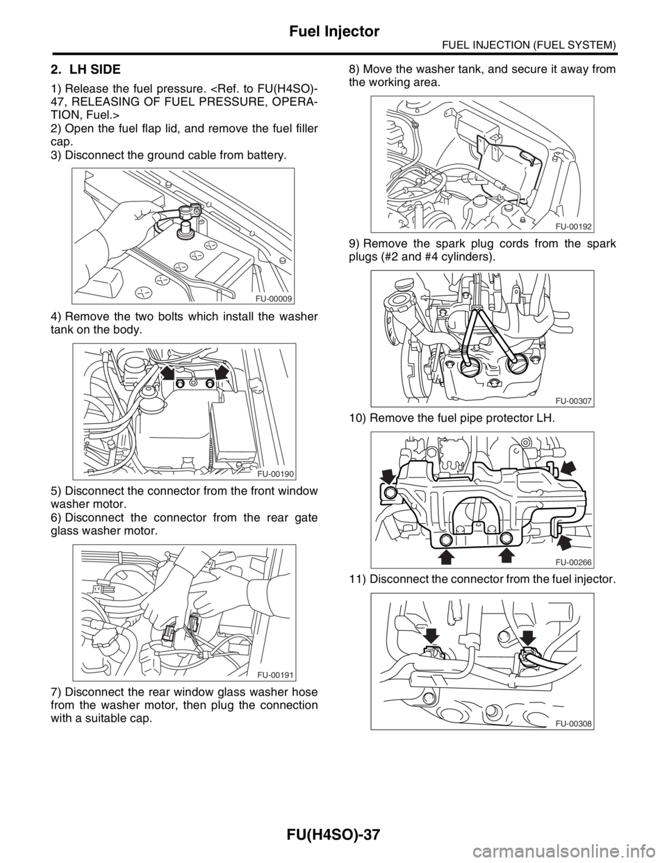
2. LH SIDE
1) Release the fuel pressure.
TION, Fuel.>
2) Open the fuel flap lid, and remove the fuel filler
cap.
3) Disconnect the ground cable from battery.
4) Remove the two bolts which install the washer
tank on the body.
5) Disconnect the connector from the front window
washer motor.
6) Disconnect the connector from the rear gate
glass washer motor.
7) Disconnect the rear window glass washer hose
from the washer motor, then plug the connection
with a suitable cap.8) Move the washer tank, and secure it away from
the working area.
9) Remove the spark plug cords from the spark
plugs (#2 and #4 cylinders).
10) Remove the fuel pipe protector LH.
11) Disconnect the connector from the fuel injector.
FU-00009
FU-00190
FU-00191
FU-00192
FU-00307
FU-00266
FU-00308
Page 884 of 2870
ME(H4SO)-15
MECHANICAL
General Description
C: CAUTION
Wear working clothing, including a cap, protec-
tive goggles and protective shoes during operation.
Remove contamination including dirt and corro-
sion before removal, installation or disassembly.
Keep the disassembled parts in order and pro-
tect them from dust or dirt.
Before removal, installation or disassembly, be
sure to clarify the failure. Avoid unnecessary re-
moval, installation, disassembly and replacement.
Be careful not to burn yourself, because each
part in the vehicle is hot after running.
Be sure to tighten bolts and nuts to the specified
torque.
Place shop jacks or rigid racks at the specified
points.
Before disconnecting electrical connectors of
sensors or units, be sure to disconnect the ground
cable from battery.
All parts should be thoroughly cleaned, paying
special attention to the engine oil passages, pis-
tons and bearings. Rotating parts and sliding parts such as piston,
bearing and gear should be coated with oil prior to
assembly.
Be careful not to let oil, grease or coolant contact
the timing belt, clutch disc and flywheel.
All removed parts, if to be reused, should be re-
installed in the original positions and directions.
Bolts, nuts and washers should be replaced with
new ones as required.
Even if necessary inspections have been made
in advance, proceed with assembly work while
making rechecks.
Remove or install engine in an area where chain
hoists, lifting devices, etc. are available for ready
use.
Be sure not to damage coated surfaces of body
panels with tools, or not to stain seats and windows
with coolant or oil. Place a cover over fenders, as
required, for protection.
Prior to starting work, prepare the following:
Service tools, clean cloth, containers to catch cool-
ant and oil, wire ropes, chain hoist, transmission
jacks, etc.
Lift-up or lower the vehicle when necessary.
Make sure to support the correct positions.
D: PREPARATION TOOL
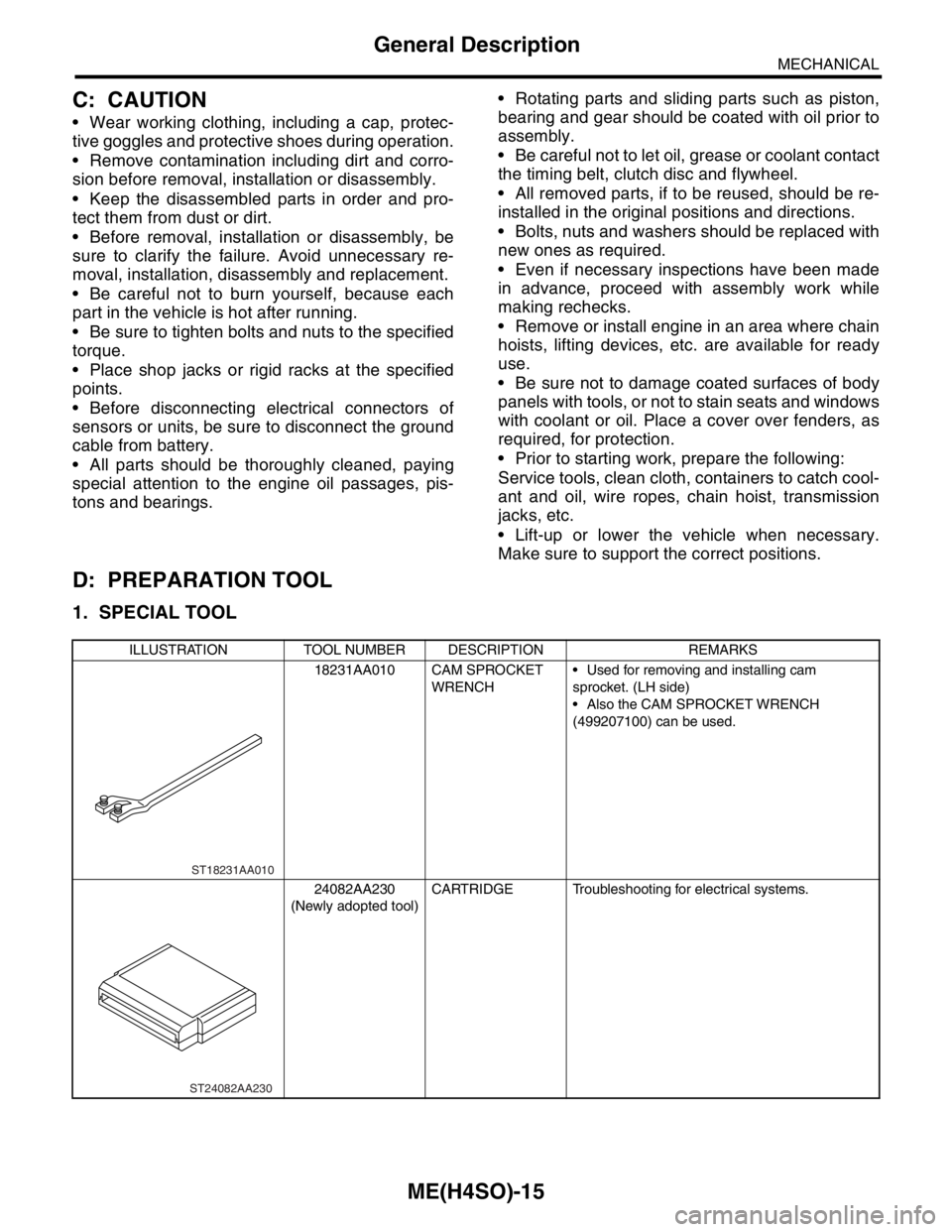
1. SPECIAL TOOL
ILLUSTRATION TOOL NUMBER DESCRIPTION REMARKS
18231AA010 CAM SPROCKET
WRENCH Used for removing and installing cam
sprocket. (LH side)
Also the CAM SPROCKET WRENCH
(499207100) can be used.
24082AA230
(Newly adopted tool)CARTRIDGE Troubleshooting for electrical systems.
ST18231AA010
ST24082AA230