Page 72 of 2870

AC-16
HVAC SYSTEM (AUTO A/C)(DIAGNOSTIC)
Diagnostics for A/C System Malfunction
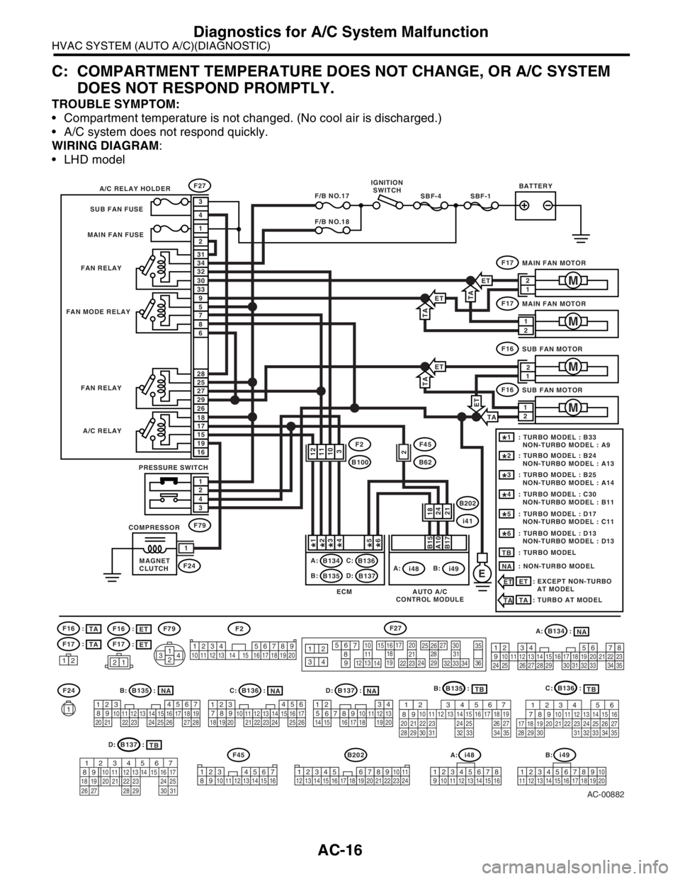
C: COMPARTMENT TEMPERATURE DOES NOT CHANGE, OR A/C SYSTEM
DOES NOT RESPOND PROMPTLY.
TROUBLE SYMPTOM:
Compartment temperature is not changed. (No cool air is discharged.)
A/C system does not respond quickly.
WIRING DIAGRAM:
LHD model
AC-00882
A: B134 :
B: B135 :
B202
D: B137 :C: B136 :
F2F27
EA:
i48
F27
F17
F79
F45
B62
B202
i41
F24
F24
F16F79
F45
F17
B:
i49A:
B134 B136
B135 B137C:
B:D:IGNITION
SWITCHBATTERY
A/C RELAY HOLDER
FAN RELAY
FAN RELAY
A/C RELAY
PRESSURE SWITCH
COMPRESSOR
MAGNET
CLUTCH FAN MODE RELAYSUB FAN FUSE
MAIN FAN FUSE
MAIN FAN MOTOR
1
M
SBF-1SBF-4F/B NO.17
F/B NO.18
1
2
3
2
1
4
3033
32 31
34
86
7 9
5
2926
27 28
25
1916
15 18
17
43
21
B15A10B17
F17
MAIN FAN MOTOR
M
F16
SUB FAN MOTOR
M
F16
SUB FAN MOTOR
M
1
2112 1314
15 16171819
20
10
1121222324
2526272829
3031323334
35
36
12
93456
7
82 314
567
82 1
94
310
24 22 23 251112131415
26 27
281617181920 21
4
1
53
2618 15 167891011
17 19
20121314
1234567891011121314151617181920212223242526272829303132333435
AUTO A/C
CONTROL MODULE ECM
2421
1234 5678910 11 12 13 14 15 16 17 18 19 20
123 4567
8910 11 12 13 14 15 16
56
78 2 1
94
310
24 22 23 251112131415
261617181920 21
34 12 8910 11
12 13 14 15 16 17 18 19 20 21 22 23 24567
D: B137 :
B: B135 :C: B136 :
A: i48
12345678
910 11 12 13 14 15 16
B: i49
12345678910
11 12 13 14 15 1617 18 19 20
: TURBO MODEL : B33
NON-TURBO MODEL : A91*
: TURBO MODEL : B24
NON-TURBO MODEL : A132*
: TURBO MODEL : B25
NON-TURBO MODEL : A143*
: TURBO MODEL : C30
NON-TURBO MODEL : B114*
: TURBO MODEL : D17
NON-TURBO MODEL : C115*
: TURBO MODEL : D13
NON-TURBO MODEL : D136*
: TURBO MODELTB
: NON-TURBO MODEL
NA
: EXCEPT NON-TURBO
AT MODEL
ET
ETNA
TB
TBNANANATB
1112
10
3
18 1
*2*3*4*5*6*
2F2
B100
ET
ETTA
TA
ET
TA
ET
: TURBO AT MODEL
TATA
TA
ET
:
ET :
F16
F17
TA :
TA :
567
82 1
94 310
24 22 23 2511 12 13 14 15
26 27
2816 17 18 19
20 21
29 30 31 32 33 34 3556
782 1
94 310
24 22 23 2511 12 13
1415
26 27
2816
17 18 19 20 21
33 34 29
32 30
31 35
567
82 1
94 310
22 23 11 12 13 14 15
24 25
2616 17
18 19 20 21
27 28 29 30 31
12
1
2
2 1
12
Page 153 of 2870
AB-21
AIRBAG SYSTEM (DIAGNOSTIC)
Airbag Control Module I/O Signal
5. Airbag Control Module I/O Signal
A: WIRING DIAGRAM
1. LHD MODEL
B31(BLACK)(GREEN)
(GREEN) (YELLOW)
(YELLOW)B82
WI-03204
7
6
2
3
8
GWGRGY
GY
R
GRGB
GRL
W
GYRGRLW
19
BB28
1
R
2354
653192
AIRBAG
CIRCUIT AIRBAG
WARNING LED
IG
IGNITION RELAY
(IG) FB-33
F/B FUSE No. 14
(IG)FB-20
F/B FUSE No. 11
(IG)FB-21
F/B FUSE No. 6
(IG)
L
GR
GW
W
B
GRGR5GR
GB
B9
C8
BB10
1
2
L
W
REF. TO GND(L)-04
CHECK
CONNECTOR
DIAGNOSIS
CONNECTOR
DIAGNOSIS
TERMINAL
B31
AB1
AIRBAG CONTROL MODULE
AB3
B81
B82
B79B38i3
B37i2
TO POWER SUPPLY ROUTING
(GRAY)
B79
1234567891011121314
B
B
12
3456
B37
AB3
COMBINATION
METER B: C:
i11i10
i11
i10 B: C:
A/B(L)-01
A/B(L)-01
12345678910
123456789101112131415161718192021222324252627282930
34 128910 11
12 13 14 15 16 17 18 19 20 21 22 23 24567
1234567891011121314151617
1819202122232425262728
1
34562
B38
219
32
1234 5610 11 12 13 14 15716
23 3019 20
22 26 27 28 29817
24 3118
25
REF. TO GND(L)-02
BB
Page 171 of 2870

AB-39
AIRBAG SYSTEM (DIAGNOSTIC)
Airbag Warning Light Failure
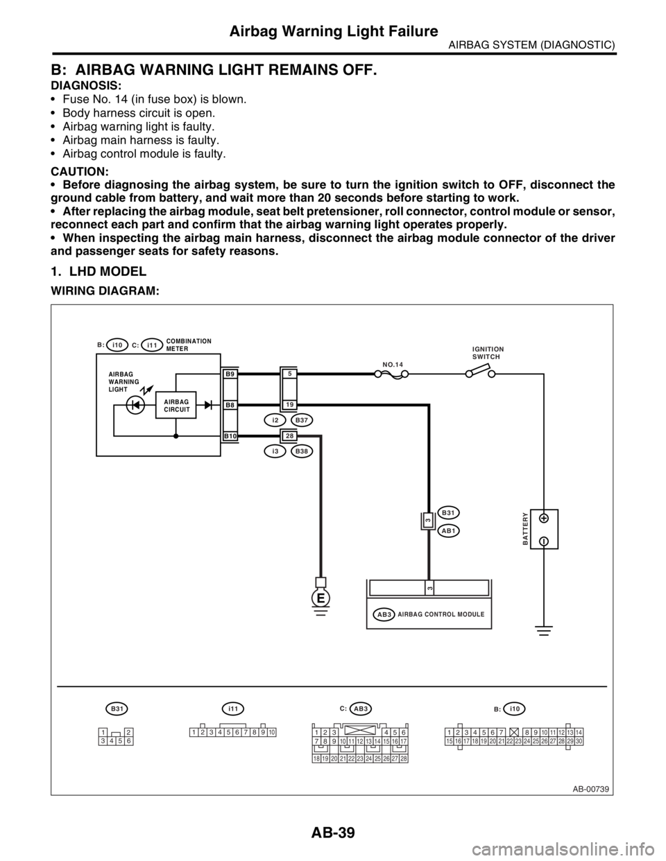
B: AIRBAG WARNING LIGHT REMAINS OFF.
DIAGNOSIS:
Fuse No. 14 (in fuse box) is blown.
Body harness circuit is open.
Airbag warning light is faulty.
Airbag main harness is faulty.
Airbag control module is faulty.
CAUTION:
Before diagnosing the airbag system, be sure to turn the ignition switch to OFF, disconnect the
ground cable from battery, and wait more than 20 seconds before starting to work.
After replacing the airbag module, seat belt pretensioner, roll connector, control module or sensor,
reconnect each part and confirm that the airbag warning light operates properly.
When inspecting the airbag main harness, disconnect the airbag module connector of the driver
and passenger seats for safety reasons.
1. LHD MODEL
WIRING DIAGRAM:
AB-00739
12
34561
2345678910123456789101112131415161718192021222324252627282930
B31 i11AB3
i10
B:
C: i10
i11
AIRBAG
WARNING
LIGHTCOMBINATION
METERB9
B8
B10
NO.14
i3B38 28
i2B37 19
5
AIRBAG CONTROL MODULEAB3
B31
AB1
3
3
AIRBAG
CIRCUIT
E
BATTERY
1234567891011121314151617
1819202122232425262728
IGNITION
SWITCH
B: C:
Page 190 of 2870
AB-58
AIRBAG SYSTEM (DIAGNOSTIC)
Diagnostic Procedure with Diagnostic Trouble Code (DTC)
H: DTC 24
DIAGNOSIS:
Airbag control module is faulty.
Airbag main harness circuit is open.
Fuse No. 11 (in fuse and relay box) is blown.
Body harness circuit is open.
CAUTION:
Before diagnosing the airbag system, be sure to turn the ignition switch to OFF, disconnect the
ground cable from battery, and wait more than 20 seconds before starting to work.
After replacing the airbag module, seat belt pretensioner, roll connector, control module or sensor,
reconnect each part and confirm that the airbag warning light operates properly.
When inspecting the airbag main harness, disconnect the driver’s airbag module and passenger’s
airbag module connectors for safety reasons.
1. LHD MODEL
WIRING DIAGRAM:
AB-00623
AB3
AIRBAG CONTROL MODULEAB3
B31
AB1
AB1
1
6
BATTERY
IG SW
NO.11
B31
12
34561
23 45 61234567891011121314151617
1819202122232425262728
Page 194 of 2870
AB-62
AIRBAG SYSTEM (DIAGNOSTIC)
Diagnostic Procedure with Diagnostic Trouble Code (DTC)
I: DTC 25
DIAGNOSIS:
Airbag control module is faulty.
Airbag main harness circuit is open.
Fuse No. 6 (in joint box) is blown.
Body harness circuit is open.
CAUTION:
Before diagnosing the airbag system, be sure to turn the ignition switch to OFF, disconnect the
ground cable from battery, and wait more than 20 seconds before starting to work.
After replacing the airbag module, seat belt pretensioner, roll connector, control module or sensor,
reconnect each part and confirm that the airbag warning light operates properly.
When inspecting the airbag main harness, disconnect the driver’s airbag module and passenger’s
airbag module connectors for safety reasons.
1. LHD MODEL
WIRING DIAGRAM:
AB-00624
AB3
AIRBAG CONTROL MODULEAB3
B31
AB1
AB1
2
5
BATTERY
IG SW
NO.6
B31
12
34561
23 45 61234567891011121314151617
1819202122232425262728
Page 294 of 2870
WW-6
WIPER AND WASHER SYSTEM
Wiper and Washer System
2. Wiper and Washer System
A: WIRING DIAGRAM
1. WIPER AND WASHER (FRONT)
2. WIPER AND WASHER (REAR)
B: INSPECTION
Symptom Repair order
Wiper and washers do not operate. (1) Wiper fuse (F/B No. 14, 15)
(2) Combination switch
(3) Wiper motor
(4) Wiring harness
Wipers do not operate in LO or HI. (1) Combination switch
(2) Wiper motor
(3) Wiring harness
Wipers do not operate in INT. (1) Combination switch
(2) Wiper motor
(3) Wiring harness
Washer motor does not operate. (1) Washer switch
(2) Washer motor
(3) Wiring harness
Wipers do not operate when washer switch is ON. (1) Washer motor
(2) Wiring harness
Washer fluid spray does not operate. (1) Washer motor
(2) Washer hose and nozzle
Page 313 of 2870
ET-3
ENTERTAINMENT
Radio System
2. Radio System
A: WIRING DIAGRAM
1. RADIO
B: INSPECTION
Symptom Repair order
No power coming in. (No display and no sound from speakers.) (1) Check the fuse and power supply for radio.
(2) Check the radio ground.
(3) Remove the radio for repair.
A specific speaker does not operate. (1) Check the speaker.
(2) Check the output circuit between radio and speaker.
Radio generates noise with engine running. (1) Check the radio ground.
(2) Check the generator.
(3) Check the ignition coil.
(4) Remove the radio for repair.
AM and FM modes are weak or noisy. (1) Check the antenna.
(2) Check the antenna amplifier.
(3) Check the noise suppressor.
(4) Check the radio ground.
(5) Remove the radio for repair.
Page 336 of 2870
GW-6
GLASS/WINDOW/MIRROR
Power Window System
2. Power Window System
A: WIRING DIAGRAM
1. POWER WINDOW
B: INSPECTION
Symptom Repair order
All power windows does not operate.(1) Fuse (SBF-6) (F/B No. 18)
(2) Power window circuit breaker
(3) Power window relay
(4) Wire harness
One window does not operate.(1) Power window main switch
(2) Power window sub switch
(3) Power window motor
(4) Wire harness
“Window Lock” does not operate. Power window main switch