2004 NISSAN TERRANO key
[x] Cancel search: keyPage 1305 of 1833
![NISSAN TERRANO 2004 Service Repair Manual HOW TO ERASE SELF-DIAGNOSIS RESULTS
With CONSULT-II
IªSELF-DIAG [CURRENT]º
A current self-diagnosis result is displayed on the CONSULT-II screen in real time.
After the malfunction is repaired compl NISSAN TERRANO 2004 Service Repair Manual HOW TO ERASE SELF-DIAGNOSIS RESULTS
With CONSULT-II
IªSELF-DIAG [CURRENT]º
A current self-diagnosis result is displayed on the CONSULT-II screen in real time.
After the malfunction is repaired compl](/manual-img/5/57394/w960_57394-1304.png)
HOW TO ERASE SELF-DIAGNOSIS RESULTS
With CONSULT-II
IªSELF-DIAG [CURRENT]º
A current self-diagnosis result is displayed on the CONSULT-II screen in real time.
After the malfunction is repaired completely, no malfunction is detected on ªSELF-DIAG [CURRENT]º.
I ªSELF-DIAG [PAST]º
Return to the ªSELF-DIAG [CURRENT]º CONSULT-II screen by pushing ªBACKº key of CONSULT-II and
select ªSELF-DIAG [CURRENT]º in SELECT DIAG MODE. Touch ªERASEº in ªSELF-DIAG [CURRENT]º
mode.
NOTE:
If the memory of the malfunction in ªSELF-DIAG [PAST]º is not erased, the User mode shows the sys-
tem malfunction by the operation of the warning lamp even if the malfunction is repaired completely.
I ªTROUBLE DIAG RECORDº
The memory of ªTROUBLE DIAG RECORDº cannot be erased.
Without CONSULT-II
After a malfunction is repaired, switch the ignition ªOFFº for at least one second, then back ªONº. Diagnosis
mode returns to the User mode. At that time, the self-diagnostic result is cleared.
SRS701
SUPPLEMENTAL RESTRAINT SYSTEM (SRS)
Trouble Diagnoses Introduction (Cont'd)
RS-30
http://vnx.su/
Page 1315 of 1833
![NISSAN TERRANO 2004 Service Repair Manual If no malfunction is detected on ªSELF-DIAG [CURRENT]º but mal-
function is indicated by the ªAIR BAGº warning lamp, go to DIAG-
NOSTIC PROCEDURE 4, page RS-44, to diagnose the following
situation NISSAN TERRANO 2004 Service Repair Manual If no malfunction is detected on ªSELF-DIAG [CURRENT]º but mal-
function is indicated by the ªAIR BAGº warning lamp, go to DIAG-
NOSTIC PROCEDURE 4, page RS-44, to diagnose the following
situation](/manual-img/5/57394/w960_57394-1314.png)
If no malfunction is detected on ªSELF-DIAG [CURRENT]º but mal-
function is indicated by the ªAIR BAGº warning lamp, go to DIAG-
NOSTIC PROCEDURE 4, page RS-44, to diagnose the following
situations:
ISelf-diagnostic result ªSELF-DIAG [PAST]º (previously stored
in the memory) might not be erased after repair.
I The SRS system malfunctions intermittently.
8. Touch ªPRINTº.
9. Compare diagnostic codes to ªCONSULT-II Diagnostic Code Chartº, page RS-40.
10. Touch ªBACKº key of CONSULT-II until ªSELECT SYSTEMº appears in order to return to User mode from Diagnosis mode.
11. Turn ignition switch ªOFFº, then turn off and disconnect CONSULT-II, and disconnect both battery cables.
12. Repair the system as outlined by the ªRepair orderº in ªCON- SULT-II Diagnostic Code Chartº, that corresponds to the self-
diagnostic result. For replacement procedure of component
parts, refer to RS-13.
13. After repairing the system, go to DIAGNOSTIC PROCEDURE 3, page RS-42 for final checking.
CONSULT-II DIAGNOSTIC CODE CHART (ªSELF-DIAG
[CURRENT]º)
Diagnostic item Explanation Repair order
ªRecheck SRS at each replacement.º
NO DTC IS
DETECTED. When malfunction is
indicated by the ªAIR
BAGº warning lamp is
user mode.I
Self-diagnostic result ªSELF-DIAG
[PAST]º (previously stored in the
memory) might not be erased after
repair.
I Intermittent malfunction has been
detected in the past. I
Go to DIAGNOSTIC PROCEDURE 4
(RS-42) after charging battery.
I No malfunction is detected. IGo to DIAGNOSTIC PROCEDURE 3
(RS-42).
AIRBAG MODULE
[OPEN] I
Driver air bag module circuit is open. (including the spiral
cable) 1. Visually check the wiring harness
connection.
2. Replace the harness if it has visible damage.
3. Replace the spiral cable.
4. Replace driver air bag module. (Before disposal, it must be
deployed.)
5. Replace the diagnosis sensor unit.
6. Replace the related harness.
AIRBAG MODULE
[VB-SHORT]
I
Driver air bag module circuit is shorted to a power supply cir-
cuit. (including the spiral cable)
AIRBAG MODULE
[GND-SHORT] I
Driver air bag module circuit is shorted to ground. (including
the spiral cable)
AIRBAG MODULE
[SHORT] I
Driver air bag module circuit is shorted between wires.
SRS701
SUPPLEMENTAL RESTRAINT SYSTEM (SRS)
Trouble Diagnoses with CONSULT-II (Cont'd)
RS-40
http://vnx.su/
Page 1319 of 1833
![NISSAN TERRANO 2004 Service Repair Manual 9. Touch ªBACKº key of CONSULT-II to ªSELECT SYSTEMºscreen. Touch ªSELF-DIAG [PAST]º.
10. Check that no malfunction is detected on ªSELF-DIAG [PAST]º.
11. Touch ªBACKº key of CONSULT-II unti NISSAN TERRANO 2004 Service Repair Manual 9. Touch ªBACKº key of CONSULT-II to ªSELECT SYSTEMºscreen. Touch ªSELF-DIAG [PAST]º.
10. Check that no malfunction is detected on ªSELF-DIAG [PAST]º.
11. Touch ªBACKº key of CONSULT-II unti](/manual-img/5/57394/w960_57394-1318.png)
9. Touch ªBACKº key of CONSULT-II to ªSELECT SYSTEMºscreen. Touch ªSELF-DIAG [PAST]º.
10. Check that no malfunction is detected on ªSELF-DIAG [PAST]º.
11. Touch ªBACKº key of CONSULT-II until ªSELECT SYSTEMº appears in order to return to User mode from Diagnosis mode.
12. Turn ignition switch ªOFFº, then turn off and disconnect CON- SULT-II.
13. Go to ªSRS Operation Checkº, page RS-38 to check SRS operation by using ªAIR BAGº warning lamp with User mode.
DIAGNOSTIC PROCEDURE 4 (CONTINUED FROM
DIAGNOSTIC PROCEDURE 2)
Inspecting SRS malfunctioning record
1 CONSIDER POSSIBILITY OF NOT ERASING SELF-DIAGNOSTIC RESULT AFTER REPAIRING
Is it the first time for maintenance of SRS?
YesorNo
Ye s EGo to DIAGNOSTIC PROCEDURE 5 (RS-44).
No ESelf-diagnostic result ªSELF-DIAG [PAST]º (previously stored in the memory) might not be erased after repair. Go
to DIAGNOSTIC PROCEDURE 3, step 8 (RS-42).
DIAGNOSTIC PROCEDURE 5
Inspecting SRS intermittent malfunction by using CONSULT-II
Ð Diagnosis mode
1. Turn ignition switch ªOFFº.
2. Connect CONSULT-II to data link connector.
SRS697
SRS702
NRS122
SUPPLEMENTAL RESTRAINT SYSTEM (SRS)
Trouble Diagnoses with CONSULT-II (Cont'd)
RS-44
http://vnx.su/
Page 1321 of 1833

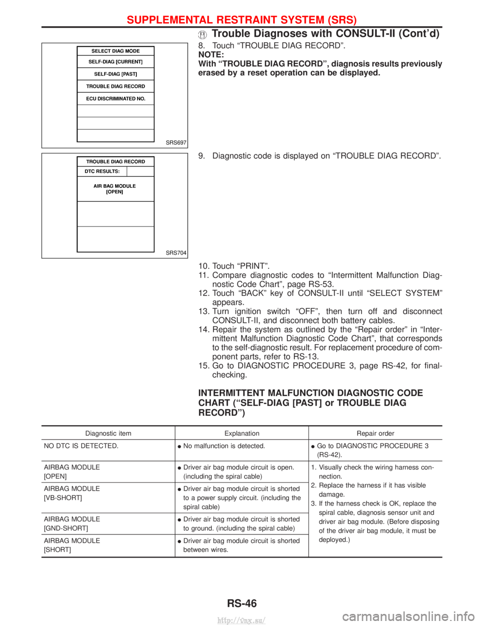
8. Touch ªTROUBLE DIAG RECORDº.
NOTE:
With ªTROUBLE DIAG RECORDº, diagnosis results previously
erased by a reset operation can be displayed.
9. Diagnostic code is displayed on ªTROUBLE DIAG RECORDº.
10. Touch ªPRINTº.
11. Compare diagnostic codes to ªIntermittent Malfunction Diag-nostic Code Chartº, page RS-53.
12. Touch ªBACKº key of CONSULT-II until ªSELECT SYSTEMº appears.
13. Turn ignition switch ªOFFº, then turn off and disconnect CONSULT-II, and disconnect both battery cables.
14. Repair the system as outlined by the ªRepair orderº in ªInter- mittent Malfunction Diagnostic Code Chartº, that corresponds
to the self-diagnostic result. For replacement procedure of com-
ponent parts, refer to RS-13.
15. Go to DIAGNOSTIC PROCEDURE 3, page RS-42, for final- checking.
INTERMITTENT MALFUNCTION DIAGNOSTIC CODE
CHART (ªSELF-DIAG [PAST] or TROUBLE DIAG
RECORDº)
Diagnostic item ExplanationRepair order
NO DTC IS DETECTED. INo malfunction is detected. IGo to DIAGNOSTIC PROCEDURE 3
(RS-42).
AIRBAG MODULE
[OPEN] I
Driver air bag module circuit is open.
(including the spiral cable) 1. Visually check the wiring harness con-
nection.
2. Replace the harness if it has visible damage.
3. If the harness check is OK, replace the spiral cable, diagnosis sensor unit and
driver air bag module. (Before disposing
of the driver air bag module, it must be
deployed.)
AIRBAG MODULE
[VB-SHORT]
I
Driver air bag module circuit is shorted
to a power supply circuit. (including the
spiral cable)
AIRBAG MODULE
[GND-SHORT] I
Driver air bag module circuit is shorted
to ground. (including the spiral cable)
AIRBAG MODULE
[SHORT] I
Driver air bag module circuit is shorted
between wires.
SRS697
SRS704
SUPPLEMENTAL RESTRAINT SYSTEM (SRS)
Trouble Diagnoses with CONSULT-II (Cont'd)
RS-46
http://vnx.su/
Page 1517 of 1833

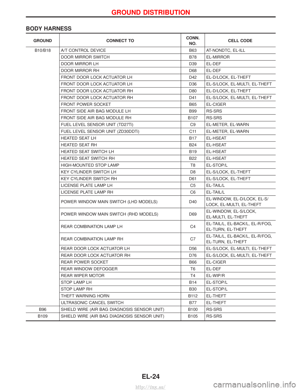
BODY HARNESS
GROUNDCONNECT TO CONN.
NO. CELL CODE
B10/B18 A/T CONTROL DEVICE B63 AT-NONDTC, EL-ILL
DOOR MIRROR SWITCH B78 EL-MIRROR
DOOR MIRROR LH D39 EL-DEF
DOOR MIRROR RH D68 EL-DEF
FRONT DOOR LOCK ACTUATOR LH D42 EL-D/LOCK, EL-THEFT
FRONT DOOR LOCK ACTUATOR LH D36 EL-S/LOCK, EL-MULTI, EL-THEFT
FRONT DOOR LOCK ACTUATOR RH D80 EL-D/LOCK, EL-THEFT
FRONT DOOR LOCK ACTUATOR RH D41 EL-S/LOCK, EL-MULTI, EL-THEFT
FRONT POWER SOCKET B65 EL-CIGER
FRONT SIDE AIR BAG MODULE LH B99 RS-SRS
FRONT SIDE AIR BAG MODULE RH B107 RS-SRS
FUEL LEVEL SENSOR UNIT (TD27Ti) C9 EL-METER, EL-WARN
FUEL LEVEL SENSOR UNIT (ZD30DDTi) C11 EL-METER, EL-WARN
HEATED SEAT LH B17 EL-HSEAT
HEATED SEAT RH B24 EL-HSEAT
HEATED SEAT SWITCH LH B19 EL-HSEAT
HEATED SEAT SWITCH RH B22 EL-HSEAT
HIGH-MOUNTED STOP LAMP T8 EL-STOP/L
KEY CYLINDER SWITCH LH D8 EL-S/LOCK, EL-THEFT
KEY CYLINDER SWITCH RH D61 EL-S/LOCK, EL-THEFT
LICENSE PLATE LAMP LH C5 EL-TAIL/L
LICENSE PLATE LAMP RH C6 EL-TAIL/L
POWER WINDOW MAIN SWITCH (LHD MODELS) D40EL-WINDOW, EL-D/LOCK, EL-S/
LOCK, EL-MULTI, EL-THEFT
POWER WINDOW MAIN SWITCH (RHD MODELS) D69EL-WINDOW, EL-S/LOCK,
EL-MULTI, EL-THEFT
REAR COMBINATION LAMP LH C4EL-TAIL/L, EL-BACK/L, EL-R/FOG,
EL-TURN, EL-THEFT
REAR COMBINATION LAMP RH C7EL-TAIL/L, EL-BACK/L, EL-R/FOG,
EL-TURN, EL-THEFT
REAR DOOR LOCK ACTUATOR LH D56 EL-S/LOCK, EL-MULTI, EL-THEFT
REAR DOOR LOCK ACTUATOR RH D76 EL-S/LOCK, EL-MULTI, EL-THEFT
REAR POWER SOCKET B66 EL-CIGER
REAR WINDOW DEFOGGER T6 EL-DEF
REAR WIPER MOTOR T4 EL-WIP/R
STOP LAMP LH B14 EL-STOP/L
STOP LAMP RH B30 EL-STOP/L
THEFT WARNING HORN B112 EL-THEFT
ULTRASONIC CANCEL SWITCH B77 EL-THEFT
B96 SHIELD WIRE (AIR BAG DIAGNOSIS SENSOR UNIT) B100 RS-SRS
B109 SHIELD WIRE (AIR BAG DIAGNOSIS SENSOR UNIT) B105 RS-SRS
GROUND DISTRIBUTION
EL-24
http://vnx.su/
Page 1565 of 1833
![NISSAN TERRANO 2004 Service Repair Manual System Description
POWER SUPPLY AND GROUND
Power is supplied at all times:
Ithrough 15A fuse [No. 5, located in the fuse block (J/B)]
I to time control unit terminal U09,
I through 10A fuse [No. 16, l NISSAN TERRANO 2004 Service Repair Manual System Description
POWER SUPPLY AND GROUND
Power is supplied at all times:
Ithrough 15A fuse [No. 5, located in the fuse block (J/B)]
I to time control unit terminal U09,
I through 10A fuse [No. 16, l](/manual-img/5/57394/w960_57394-1564.png)
System Description
POWER SUPPLY AND GROUND
Power is supplied at all times:
Ithrough 15A fuse [No. 5, located in the fuse block (J/B)]
I to time control unit terminal U09,
I through 10A fuse [No. 16, located in the fuse block (J/B)]
I to front interior lamp terminal 1,
I to rear interior lamp terminal 1 (Wagon models)
I to rear room lamp terminal 2 (Hardtop models)
I to sunroof switch and map lamps terminal 3 (with sunroof),
I to map lamp terminal 2 (without sunroof).
Ground is supplied:
I through body grounds terminals F36, F47 (LHD models) or M33, M754 (RHD models).
I through fuse block terminal MM2
I to time control unit terminal U16
When the driver side door is opened, ground is supplied:
I through driver side door switch case ground and terminal 1, and
I through fuse block terminal B07
I to time control unit terminal U06
When any door is opened, ground is supplied:
I through case ground and terminal 1 of each door switch,
I through fuse block terminal B01
I to time control unit terminal U07.
When the driver side door is unlocked by the door lock/unlock switch, the time control unit receives a ground
signal:
I through body grounds B10 and B18
I to power window main switch terminal 3
I from power window main switch terminal 7
I to time control unit terminal U37.
When a signal, or combination of signals is received by the time control unit, ground is supplied:
I through time control unit terminal U12 and fuse block terminal R01
I to front interior room lamp terminal 2.
I to rear interior lamp terminal 2 (Wagon models).
I to rear interior room lamp terminal 1 (Hardtop models).
With power and ground supplied, the interior room lamps illuminate when the lamp switch is in ªDOORº posi-
tion.
SWITCH OPERATION
When interior room lamp switch is in ªONº position, ground is supplied:
I through front interior lamp case ground.
I through rear interior lamp case ground (Wagon models).
When sunroof switch and map lamps (with sunroof) is ON, ground is supplied:
I through body grounds F36, F47 (LHD models) or M33, M754 (RHD models)
I through fuse block terminal MM2 and R03
I to sunroof switch map lamps terminal 2.
When map lamp (without sunroof) is ON, ground is supplied:
I through body grounds F36, F47 (LHD models) or M33, M754 (RHD models)
I through fuse block terminal MM2 and R03
I to map lamp terminal 1.
With power and ground supplied, the interior room lamps, map lamps illuminate.
INTERIOR ROOM LAMP TIMER OPERATION
When interior room lamp switch is in the ªDOORº position, the time control unit keeps the interior room lamp
illuminated for about 30 seconds when:
I unlock signal is supplied from door lock/unlock switch while all doors are closed
I unlock signal is supplied from remote controller or door key cylinder while all doors are closed
I driver's door is opened and then closed
The timer is canceled when:
I driver's door is locked,
INTERIOR LAMP
EL-72
http://vnx.su/
Page 1656 of 1833

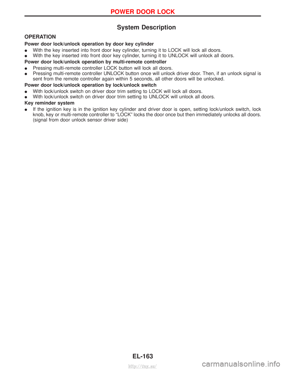
System Description
OPERATION
Power door lock/unlock operation by door key cylinder
IWith the key inserted into front door key cylinder, turning it to LOCK will lock all doors.
I With the key inserted into front door key cylinder, turning it to UNLOCK will unlock all doors.
Power door lock/unlock operation by multi-remote controller
I Pressing multi-remote controller LOCK button will lock all doors.
I Pressing multi-remote controller UNLOCK button once will unlock driver door. Then, if an unlock signal is
sent from the remote controller again within 5 seconds, all other doors will be unlocked.
Power door lock/unlock operation by lock/unlock switch
I With lock/unlock switch on driver door trim setting to LOCK will lock all doors.
I With lock/unlock switch on driver door trim setting to UNLOCK will unlock all doors.
Key reminder system
I If the ignition key is in the ignition key cylinder and driver door is open, setting lock/unlock switch, lock
knob, key or multi-remote controller to ªLOCKº locks the door once but then immediately unlocks all doors.
(signal from door unlock sensor driver side)
POWER DOOR LOCK
EL-163
http://vnx.su/
Page 1664 of 1833

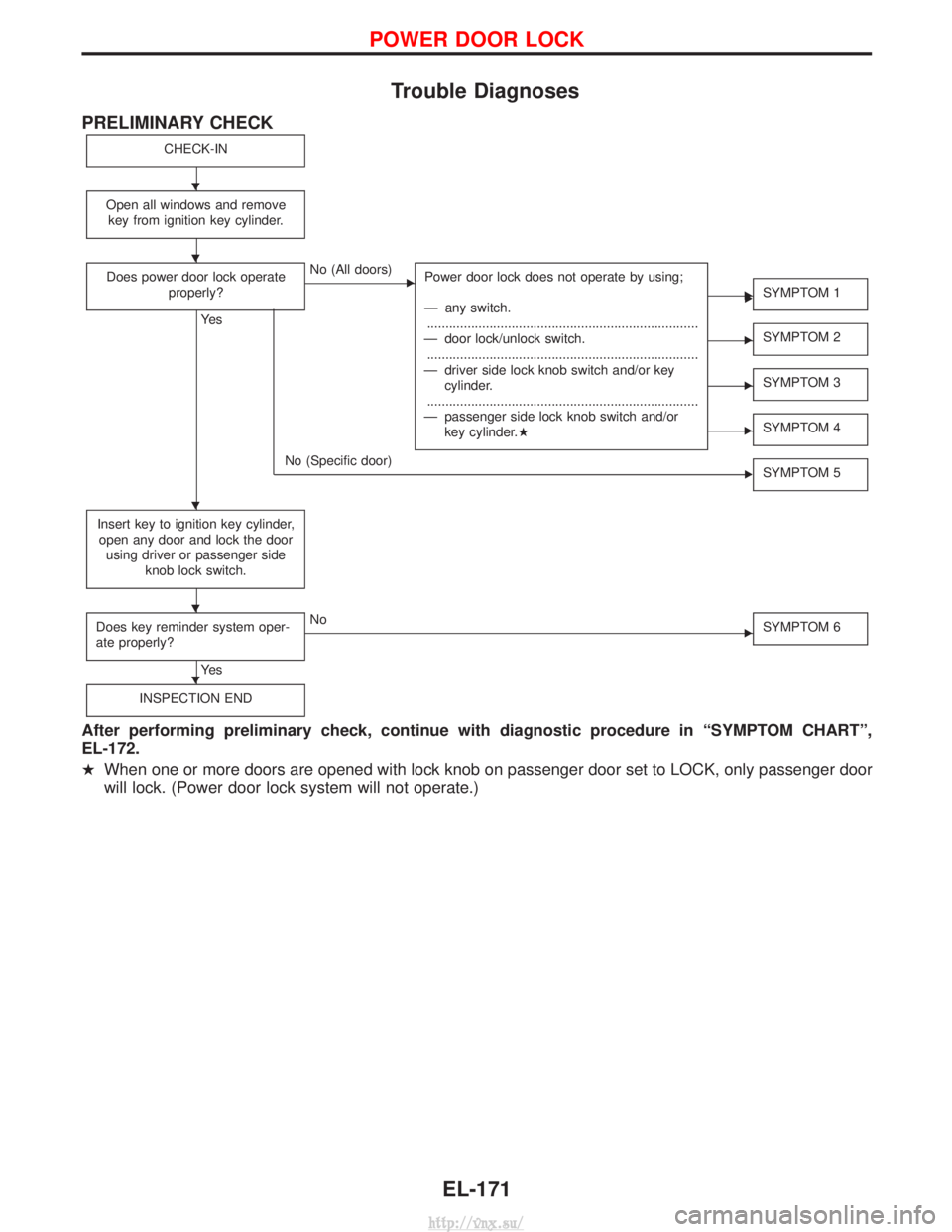
Trouble Diagnoses
PRELIMINARY CHECK
CHECK-IN
Open all windows and removekey from ignition key cylinder.
Does power door lock operate properly?
Ye s
ENo (All doors) Power door lock does not operate by using;
Ð any switch.
........................................................................\
..
Ð door lock/unlock switch. ........................................................................\
..
Ð driver side lock knob switch and/or key cylinder.
........................................................................\
..
Ð passenger side lock knob switch and/or key cylinder.H
ESYMPTOM 1
ESYMPTOM 2
ESYMPTOM 3
ESYMPTOM 4
No (Specific door) SYMPTOM 5
Insert key to ignition key cylinder,
open any door and lock the door using driver or passenger side knob lock switch.
Does key reminder system oper-
ate properly?
Ye s
ENo SYMPTOM 6
INSPECTION END
After performing preliminary check, continue with diagnostic procedure in ªSYMPTOM CHARTº,
EL-172.
HWhen one or more doors are opened with lock knob on passenger door set to LOCK, only passenger door
will lock. (Power door lock system will not operate.)
E E
H
H
H
H
H
POWER DOOR LOCK
EL-171
http://vnx.su/