Page 818 of 1833
IBefore assembly, apply a coat of recommended ATF to all parts. Apply petroleum jelly to protect O-rings
and seals, and to hold bearings and washers in place during assembly. Do not use grease.
I Extreme care should be taken to avoid damage to O-rings, seals and gaskets when assembling.
I After overhaul, refill the transmission with new ATF.
I When the A/T drain plug is removed, only some of the fluid is drained. Old A/T fluid will remain in torque
converter and ATF cooling system.
Always follow the procedures under ªChanging A/T Fluidº in the MA section when changing A/T fluid.
Service Notice or Precautions
FAIL-SAFE
The TCM has an electronic Fail-Safe (limp home mode). This allows the vehicle to be driven even if a major
electrical input/output device circuit is damaged.
Under Fail-Safe, the vehicle always runs in third gear even with a shift lever position of ª1º, ª2º or ªDº. Cus-
tomer may complain of ªsluggish or poor accelerationº.
When the Fail-Safe operation occurs the next time the key is turned to the ªONº position, the SPORT indica-
tor lamp will blink for about 8 seconds. (For diagnosis, refer to AT-33.)
Fail-Safe may activate without electrical circuit damages if the vehicle is driven under extreme conditions (such
as excessive wheel spins and emergency braking immediately afterwards). In this case, turn the ignition key
ªOFFº for 5 seconds and then ªONº to recover normal shift pattern.
The blinking of the SPORT indicator lamp for about 8 seconds will appear only once and be cleared. The cus-
tomer may resume normal driving conditions by chance.
Always follow the ªWORK FLOWº (Refer to AT-26).
The SELF-DIAGNOSIS results will be as follows:
The first SELF-DIAGNOSIS will indicate the damage of the vehicle speed sensor or the revolution sensor.
During the next SELF-DIAGNOSIS performed after checking the sensor, no damages will be indicated.
PREPARATION AND PRECAUTIONS
Precautions (Cont'd)
AT- 5
http://vnx.su/
Page 836 of 1833
Diagnostic Worksheet
INFORMATION FROM CUSTOMER
KEY POINTS
WHAT......................... Vehicle & A/T model
WHEN ......................... Date, Frequencies
WHERE ...................... Road conditions
HOW ........................... Operating conditions, Symptoms
Customer name MR/MS Model & Year VIN
Trans. model EngineMileage
Incident Date Manuf. DateIn Service Date
Frequency lContinuous lIntermittent ( times a day)
Symptoms lVehicle does not move. (l Any positionlParticular position)
l No up-shift (l 1st,2nd l2nd ,3rd l3rd ,O/D)
l No down-shift (l O/D,3rd l3rd ,2nd l2nd ,1st)
l Lockup malfunction
l Shift point too high or too low.
l Shift shock or slip ( lN, D lLockup lAny drive position)
l Noise or vibration
l No kickdown
l No pattern select
l Others
( )
SPORT indicator lamp Blinks for about 8 seconds.
l Continuously lit lNot lit
Malfunction indicator lamp
(MIL) l
Continuously lit lNot lit
TROUBLE DIAGNOSIS Ð Introduction
AT-23
http://vnx.su/
Page 911 of 1833
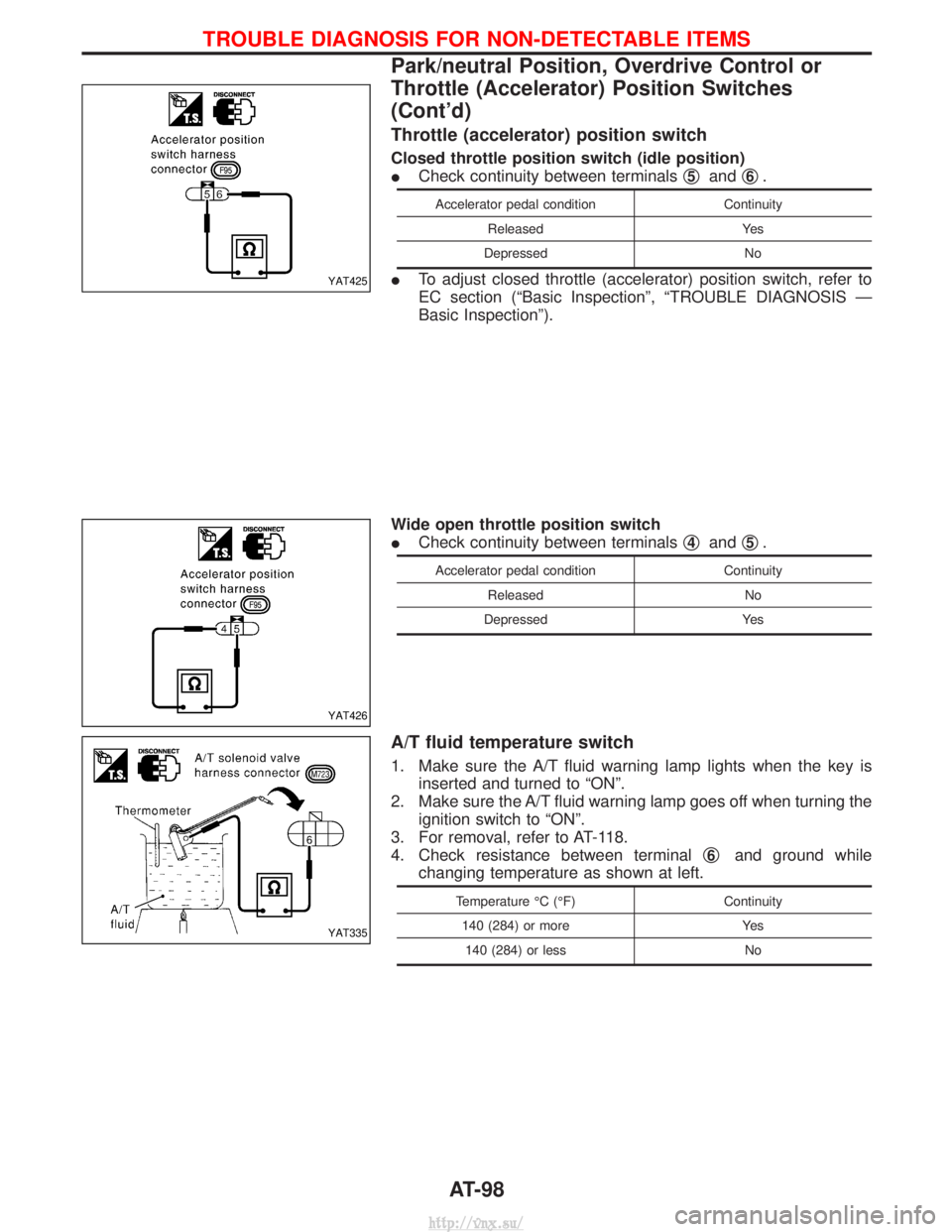
Throttle (accelerator) position switch
Closed throttle position switch (idle position)
ICheck continuity between terminals q
5andq6.
Accelerator pedal condition
Continuity
Released Yes
Depressed No
ITo adjust closed throttle (accelerator) position switch, refer to
EC section (ªBasic Inspectionº, ªTROUBLE DIAGNOSIS Ð
Basic Inspectionº).
Wide open throttle position switch
I Check continuity between terminals q
4andq5.
Accelerator pedal condition
Continuity
Released No
Depressed Yes
A/T fluid temperature switch
1. Make sure the A/T fluid warning lamp lights when the key is
inserted and turned to ªONº.
2. Make sure the A/T fluid warning lamp goes off when turning the ignition switch to ªONº.
3. For removal, refer to AT-118.
4. Check resistance between terminal q
6and ground while
changing temperature as shown at left.
Temperature ÉC (ÉF) Continuity
140 (284) or more Yes
140 (284) or less No
YAT425
YAT426
YAT335
TROUBLE DIAGNOSIS FOR NON-DETECTABLE ITEMS
Park/neutral Position, Overdrive Control or
Throttle (Accelerator) Position Switches
(Cont'd)
AT-98
http://vnx.su/
Page 1231 of 1833
ACTIVE TEST PROCEDURE
IWhen conducting Active test, vehicle must be stationary.
I When ABS warning lamp stays on, never conduct Active test.
1) Turn ignition switch to the ªLOCKº position.
2) Connect CONSULT-II to Data Link Connector.
3) Start engine.
1) Touch ªSTARTº on CONSULT-II screen.
2) Touch ªABSº.
3) Touch ªACTIVE TESTº.
1) Select active test item by touching screen.
2) Touch ªSTARTº.
Carry out the active test by touching screen key.
C2NCS01
C2SSE01
C2SDM01
C2STI01
C2FRS01
H
H
H
TROUBLE DIAGNOSES
CONSULT-II Inspection Procedure (Cont'd)
BR-64
http://vnx.su/
Page 1263 of 1833
Disassembly and Assembly
L.H.D., R.H.D.
IWhen disassembling and assembling, unlock steering lock with
key.
I Install snap ring on upper shaft with box wrench.
YST065
NST007
SST628A
STEERING WHEEL AND STEERING COLUMN
ST-10
http://vnx.su/
Page 1264 of 1833
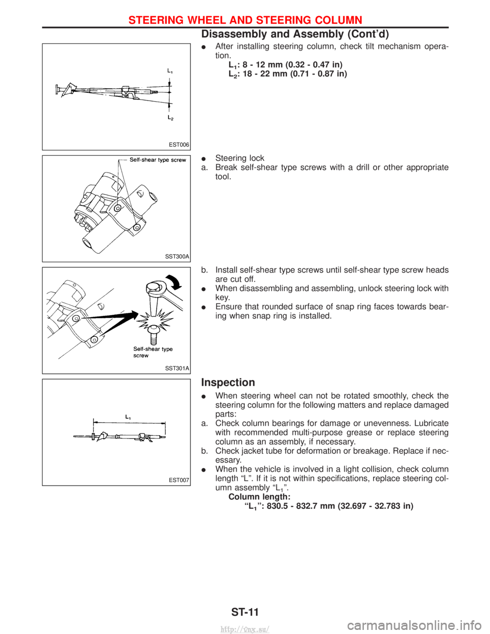
IAfter installing steering column, check tilt mechanism opera-
tion.
L
1:8-12mm (0.32 - 0.47 in)
L
2: 18 - 22 mm (0.71 - 0.87 in)
I Steering lock
a. Break self-shear type screws with a drill or other appropriate tool.
b. Install self-shear type screws until self-shear type screw heads are cut off.
I When disassembling and assembling, unlock steering lock with
key.
I Ensure that rounded surface of snap ring faces towards bear-
ing when snap ring is installed.
Inspection
IWhen steering wheel can not be rotated smoothly, check the
steering column for the following matters and replace damaged
parts:
a. Check column bearings for damage or unevenness. Lubricate with recommended multi-purpose grease or replace steering
column as an assembly, if necessary.
b. Check jacket tube for deformation or breakage. Replace if nec- essary.
I When the vehicle is involved in a light collision, check column
length ªLº. If it is not within specifications, replace steering col-
umn assembly ªL
1º.
Column length: ªL
1º: 830.5 - 832.7 mm (32.697 - 32.783 in)
EST006
SST300A
SST301A
EST007
STEERING WHEEL AND STEERING COLUMN
Disassembly and Assembly (Cont'd)
ST-11
http://vnx.su/
Page 1287 of 1833
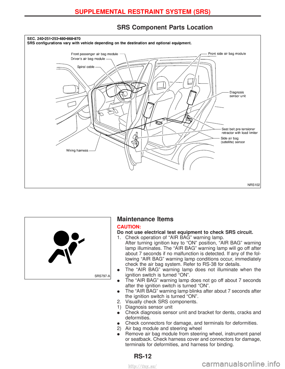
SRS Component Parts Location
Maintenance Items
CAUTION:
Do not use electrical test equipment to check SRS circuit.
1. Check operation of ªAIR BAGº warning lamp.After turning ignition key to ªONº position, ªAIR BAGº warning
lamp illuminates. The ªAIR BAGº warning lamp will go off after
about 7 seconds if no malfunction is detected. If any of the fol-
lowing ªAIR BAGº warning lamp conditions occur, immediately
check the air bag system. Refer to RS-38 for details.
I The ªAIR BAGº warning lamp does not illuminate when the
ignition switch is turned ªONº.
I The ªAIR BAGº warning lamp does not go off about 7 seconds
after the ignition switch is turned ªONº.
I The ªAIR BAGº warning lamp blinks after about 7 seconds after
the ignition switch is turned ªONº.
2. Visually check SRS components.
1) Diagnosis sensor unit
I Check diagnosis sensor unit and bracket for dents, cracks and
deformities.
I Check connectors for damage, and terminals for deformities.
2) Air bag module and steering wheel
I Remove air bag module from steering wheel, instrument panel
or seatback. Check harness cover and connectors for damage,
terminals for deformities, and harness for binding.
NRS102
SRS797-A
SUPPLEMENTAL RESTRAINT SYSTEM (SRS)
RS-12
http://vnx.su/
Page 1304 of 1833
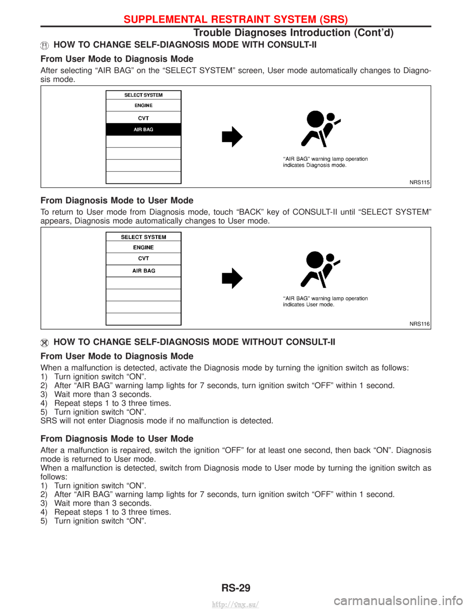
HOW TO CHANGE SELF-DIAGNOSIS MODE WITH CONSULT-II
From User Mode to Diagnosis Mode
After selecting ªAIR BAGº on the ªSELECT SYSTEMº screen, User mode automatically changes to Diagno-
sis mode.
From Diagnosis Mode to User Mode
To return to User mode from Diagnosis mode, touch ªBACKº key of CONSULT-II until ªSELECT SYSTEMº
appears, Diagnosis mode automatically changes to User mode.
HOW TO CHANGE SELF-DIAGNOSIS MODE WITHOUT CONSULT-II
From User Mode to Diagnosis Mode
When a malfunction is detected, activate the Diagnosis mode by turning the ignition switch as follows:
1) Turn ignition switch ªONº.
2) After ªAIR BAGº warning lamp lights for 7 seconds, turn ignition switch ªOFFº within 1 second.
3) Wait more than 3 seconds.
4) Repeat steps 1 to 3 three times.
5) Turn ignition switch ªONº.
SRS will not enter Diagnosis mode if no malfunction is detected.
From Diagnosis Mode to User Mode
After a malfunction is repaired, switch the ignition ªOFFº for at least one second, then back ªONº. Diagnosis
mode is returned to User mode.
When a malfunction is detected, switch from Diagnosis mode to User mode by turning the ignition switch as
follows:
1) Turn ignition switch ªONº.
2) After ªAIR BAGº warning lamp lights for 7 seconds, turn ignition switch ªOFFº within 1 second.
3) Wait more than 3 seconds.
4) Repeat steps 1 to 3 three times.
5) Turn ignition switch ªONº.
NRS115
NRS116
SUPPLEMENTAL RESTRAINT SYSTEM (SRS)
Trouble Diagnoses Introduction (Cont'd)
RS-29
http://vnx.su/