2004 NISSAN TERRANO key
[x] Cancel search: keyPage 1694 of 1833
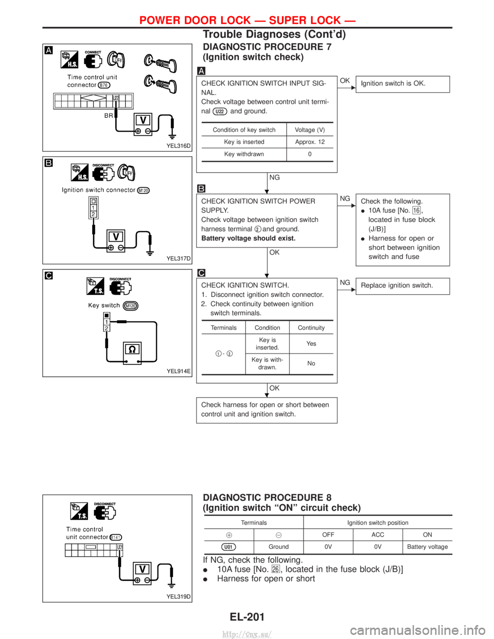
DIAGNOSTIC PROCEDURE 7
(Ignition switch check)
CHECK IGNITION SWITCH INPUT SIG-
NAL.
Check voltage between control unit termi-
nal
U22and ground.
NG
EOKIgnition switch is OK.
CHECK IGNITION SWITCH POWER
SUPPLY.
Check voltage between ignition switch
harness terminal q
2and ground.
Battery voltage should exist.
OK
ENG Check the following.
I10A fuse [No.
16,
located in fuse block
(J/B)]
I Harness for open or
short between ignition
switch and fuse
CHECK IGNITION SWITCH.
1. Disconnect ignition switch connector.
2. Check continuity between ignition switch terminals.
OK
ENG Replace ignition switch.
Check harness for open or short between
control unit and ignition switch.
Condition of key switch Voltage (V)
Key is inserted Approx. 12Key withdrawn 0
Terminals Condition Continuity
q
1-q2
Key is
inserted. Ye s
Key is with- drawn. No
DIAGNOSTIC PROCEDURE 8
(Ignition switch ªONº circuit check)
Terminals
Ignition switch position
!@ OFFACC ON
U01Ground 0V0V Battery voltage
If NG, check the following.
I10A fuse [No.
26, located in the fuse block (J/B)]
IHarness for open or short
YEL316D
YEL317D
YEL914E
YEL319D
H
H
H
POWER DOOR LOCK Ð SUPER LOCK Ð
Trouble Diagnoses (Cont'd)
EL-201
http://vnx.su/
Page 1695 of 1833
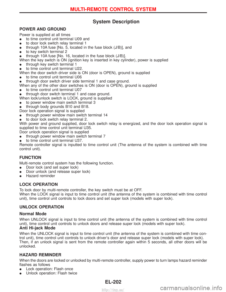
System Description
POWER AND GROUND
Power is supplied at all times
Ito time control unit terminal U09 and
I to door lock switch relay terminal 1
I through 10A fuse [No. 5, located in the fuse block (J/B)], and
I to key switch terminal 2
I through 10A fuse [No. 16, located in the fuse block (J/B)].
When the key switch is ON (ignition key is inserted in key cylinder), power is supplied
I through key switch terminal 1
I to time control unit terminal U22.
When the door switch driver side is ON (door is OPEN), ground is supplied
I to time control unit terminal U06
I through door switch driver side terminal 1 and case ground.
When any of the other door switches is ON (door is OPEN), ground is supplied
I to time control unit terminal U07
I through door switch terminal 1 and case ground.
When lock/unlock switch is LOCK, ground is supplied
I to power window main switch terminal 3
I through body grounds B10 and B18.
Door lock operation signal is supplied
I through power window main switch terminal 14
I to door lock switch relay terminal 2.
With power and ground supplied, door lock switch relay is energized, and the door lock operation signal is
supplied to time control unit terminal U35.
Door unlock operation signal is supplied
I through power window main switch terminal 7
I to time control unit terminal U37.
Remote controller signal is inputted to time control unit (The antenna of the system is combined with time
control unit).
FUNCTION
Multi-remote control system has the following function.
I Door lock (and set super lock)
I Door unlock (and release super lock)
I Hazard reminder
LOCK OPERATION
To lock door by multi-remote controller, the key switch must be at OFF.
When the LOCK signal is input to time control unit (the antenna of the system is combined with time control
unit), time control unit controls to lock doors and set super lock (models with super lock).
UNLOCK OPERATION
Normal Mode
When UNLOCK signal is input to time control unit (the antenna of the system is combined with time control
unit), time control unit controls to unlock doors and release super lock (models with super lock).
Anti Hi-jack Mode
When the UNLOCK signal is input to time control unit (the antenna of the system is combined with time con-
trol unit), time control unit controls to unlock driver's door and release super lock (models with super lock).
Then, if an unlock signal is sent from the remote controller again within 5 seconds, all other doors will be
unlocked.
HAZARD REMINDER
When the doors are locked or unlocked by multi-remote controller, supply power to turn lamps hazard reminder
flashes as follows
ILock operation: Flash once
I Unlock operation: Flash twice
MULTI-REMOTE CONTROL SYSTEM
EL-202
http://vnx.su/
Page 1696 of 1833
AUTO DOOR LOCK OPERATION
Auto lock function signal is sent for operation when any of the following signals are not sent within 5 minutes
after the unlock signal is sent from the multi-remote controller:
Iwhen door switch is turned ON for open
I when the ignition switch is turned ON
I when the lock signal is sent from the multi-remote controller
I when ignition switch is inserted in ignition key cylinder
MULTI-REMOTE CONTROLLER ID CODE ENTRY
A maximum of four remote controllers can be entered.
To enter ID code entry, the following signals must be input to the time control unit.
IIgnition switch (ON)
I Signal from remote controller
For detailed procedure, refer to ªID Code Entry Procedureº in EL-215.
MULTI-REMOTE CONTROL SYSTEM
System Description (Cont'd)
EL-203
http://vnx.su/
Page 1706 of 1833
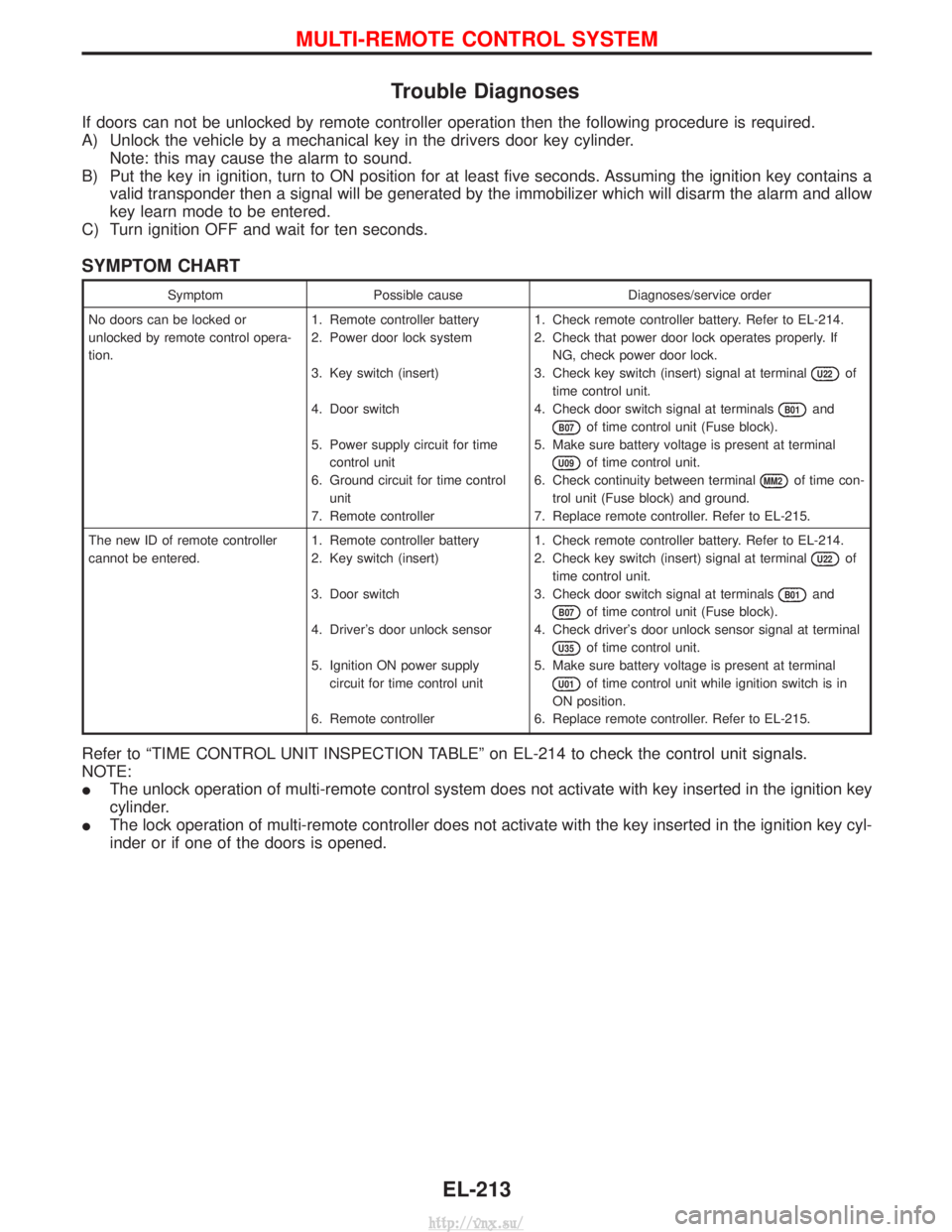
Trouble Diagnoses
If doors can not be unlocked by remote controller operation then the following procedure is required.
A) Unlock the vehicle by a mechanical key in the drivers door key cylinder.Note: this may cause the alarm to sound.
B) Put the key in ignition, turn to ON position for at least five seconds. Assuming the ignition key contains a valid transponder then a signal will be generated by the immobilizer which will disarm the alarm and allow
key learn mode to be entered.
C) Turn ignition OFF and wait for ten seconds.
SYMPTOM CHART
Symptom Possible cause Diagnoses/service order
No doors can be locked or
unlocked by remote control opera-
tion. 1. Remote controller battery
2. Power door lock system
3. Key switch (insert)
4. Door switch
5. Power supply circuit for time
control unit
6. Ground circuit for time control unit
7. Remote controller 1. Check remote controller battery. Refer to EL-214.
2. Check that power door lock operates properly. If
NG, check power door lock.
3. Check key switch (insert) signal at terminal
U22of
time control unit.
4. Check door switch signal at terminals
B01and
B07of time control unit (Fuse block).
5. Make sure battery voltage is present at terminal
U09of time control unit.
6. Check continuity between terminal
MM2of time con-
trol unit (Fuse block) and ground.
7. Replace remote controller. Refer to EL-215.
The new ID of remote controller
cannot be entered. 1. Remote controller battery
2. Key switch (insert)
3. Door switch
4. Driver's door unlock sensor
5. Ignition ON power supply
circuit for time control unit
6. Remote controller 1. Check remote controller battery. Refer to EL-214.
2. Check key switch (insert) signal at terminal
U22of
time control unit.
3. Check door switch signal at terminals
B01and
B07of time control unit (Fuse block).
4. Check driver's door unlock sensor signal at terminal
U35of time control unit.
5. Make sure battery voltage is present at terminal
U01of time control unit while ignition switch is in
ON position.
6. Replace remote controller. Refer to EL-215.
Refer to ªTIME CONTROL UNIT INSPECTION TABLEº on EL-214 to check the control unit signals.
NOTE:
I The unlock operation of multi-remote control system does not activate with key inserted in the ignition key
cylinder.
I The lock operation of multi-remote controller does not activate with the key inserted in the ignition key cyl-
inder or if one of the doors is opened.
MULTI-REMOTE CONTROL SYSTEM
EL-213
http://vnx.su/
Page 1707 of 1833
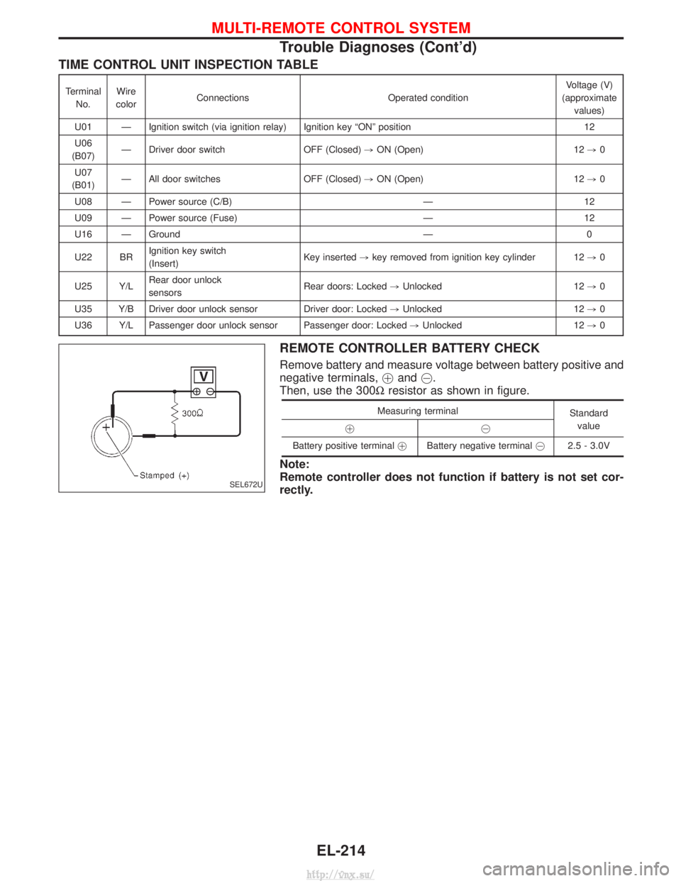
TIME CONTROL UNIT INSPECTION TABLE
TerminalNo. Wire
color Connections Operated condition Voltage (V)
(approximate values)
U01 Ð Ignition switch (via ignition relay) Ignition key ªONº position 12
U06
(B07) Ð Driver door switch OFF (Closed)
,ON (Open) 12 ,0
U07
(B01) Ð All door switches OFF (Closed)
,ON (Open) 12 ,0
U08 Ð Power source (C/B) Ð 12
U09 Ð Power source (Fuse) Ð 12
U16 Ð Ground Ð 0
U22 BR Ignition key switch
(Insert) Key inserted
,key removed from ignition key cylinder 12 ,0
U25 Y/L Rear door unlock
sensors Rear doors: Locked
,Unlocked 12 ,0
U35 Y/B Driver door unlock sensor Driver door: Locked ,Unlocked 12 ,0
U36 Y/L Passenger door unlock sensor Passenger door: Locked ,Unlocked 12 ,0
REMOTE CONTROLLER BATTERY CHECK
Remove battery and measure voltage between battery positive and
negative terminals, !and @.
Then, use the 300W resistor as shown in figure.
Measuring terminal
Standard
value
!@
Battery positive terminal !Battery negative terminal @2.5 - 3.0V
Note:
Remote controller does not function if battery is not set cor-
rectly.
SEL672U
MULTI-REMOTE CONTROL SYSTEM
Trouble Diagnoses (Cont'd)
EL-214
http://vnx.su/
Page 1708 of 1833
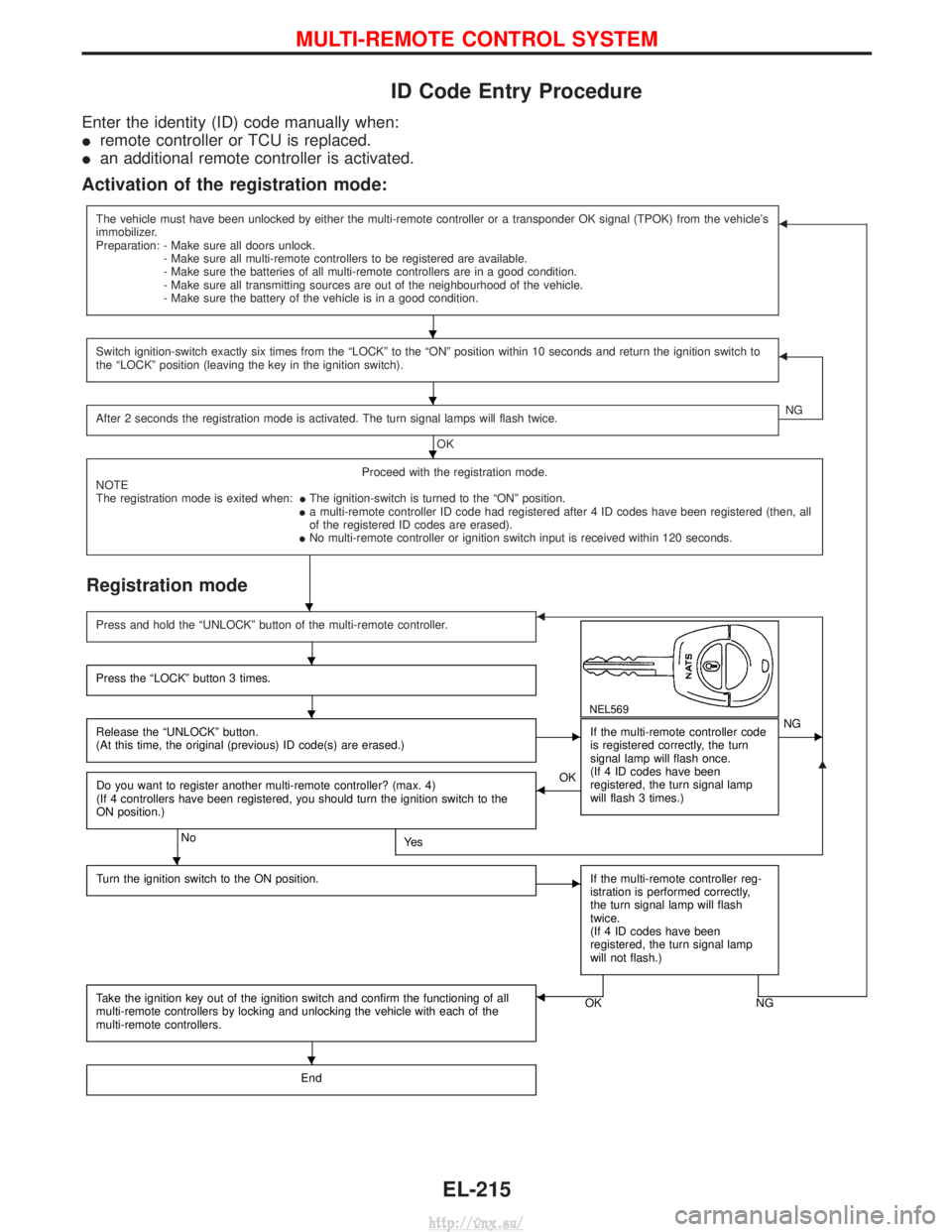
ID Code Entry Procedure
Enter the identity (ID) code manually when:
Iremote controller or TCU is replaced.
I an additional remote controller is activated.
Activation of the registration mode:
The vehicle must have been unlocked by either the multi-remote controller or a transponder OK signal (TPOK) from the vehicle's
immobilizer.
Preparation: - Make sure all doors unlock.
- Make sure all multi-remote controllers to be registered are available.
- Make sure the batteries of all multi-remote controllers are in a good condition.
- Make sure all transmitting sources are out of the neighbourhood of the vehicle.
- Make sure the battery of the vehicle is in a good condition.F
Switch ignition-switch exactly six times from the ªLOCKº to the ªONº position within 10 seconds and return the ignition switch to
the ªLOCKº position (leaving the key in the ignition switch).F
After 2 seconds the registration mode is activated. The turn signal lamps will flash twice.
OK NG
Proceed with the registration mode.
NOTE
The registration mode is exited when: IThe ignition-switch is turned to the ªONº position.
I a multi-remote controller ID code had registered after 4 ID codes have been registered (then, all
of the registered ID codes are erased).
I No multi-remote controller or ignition switch input is received within 120 seconds.
Registration mode
G
Press and hold the ªUNLOCKº button of the multi-remote controller.F
NEL569
Press the ªLOCKº button 3 times.
Release the ªUNLOCKº button.
(At this time, the original (previous) ID code(s) are erased.)EIf the multi-remote controller code
is registered correctly, the turn
signal lamp will flash once.
(If 4 ID codes have been
registered, the turn signal lamp
will flash 3 times.)ENG
Do you want to register another multi-remote controller? (max. 4)
(If 4 controllers have been registered, you should turn the ignition switch to the
ON position.)
NoYe s
FOK
Turn the ignition switch to the ON position.
EIf the multi-remote controller reg-
istration is performed correctly,
the turn signal lamp will flash
twice.
(If 4 ID codes have been
registered, the turn signal lamp
will not flash.)
Take the ignition key out of the ignition switch and confirm the functioning of all
multi-remote controllers by locking and unlocking the vehicle with each of the
multi-remote controllers.OK NGF
End
H
H
H
H
H
H
H
H
MULTI-REMOTE CONTROL SYSTEM
EL-215
http://vnx.su/
Page 1709 of 1833
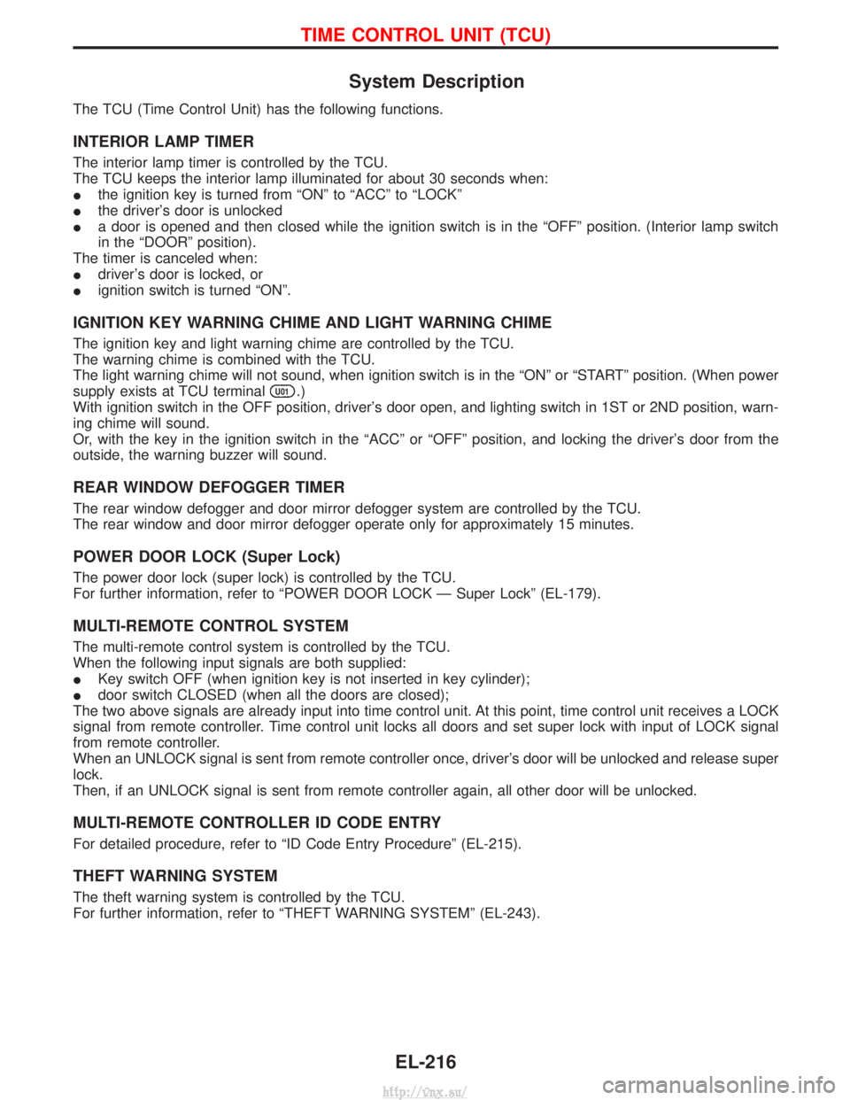
System Description
The TCU (Time Control Unit) has the following functions.
INTERIOR LAMP TIMER
The interior lamp timer is controlled by the TCU.
The TCU keeps the interior lamp illuminated for about 30 seconds when:
Ithe ignition key is turned from ªONº to ªACCº to ªLOCKº
I the driver's door is unlocked
I a door is opened and then closed while the ignition switch is in the ªOFFº position. (Interior lamp switch
in the ªDOORº position).
The timer is canceled when:
I driver's door is locked, or
I ignition switch is turned ªONº.
IGNITION KEY WARNING CHIME AND LIGHT WARNING CHIME
The ignition key and light warning chime are controlled by the TCU.
The warning chime is combined with the TCU.
The light warning chime will not sound, when ignition switch is in the ªONº or ªSTARTº position. (When power
supply exists at TCU terminal
U01.)
With ignition switch in the OFF position, driver's door open, and lighting switch in 1ST or 2ND position, warn-
ing chime will sound.
Or, with the key in the ignition switch in the ªACCº or ªOFFº position, and locking the driver's door from the
outside, the warning buzzer will sound.
REAR WINDOW DEFOGGER TIMER
The rear window defogger and door mirror defogger system are controlled by the TCU.
The rear window and door mirror defogger operate only for approximately 15 minutes.
POWER DOOR LOCK (Super Lock)
The power door lock (super lock) is controlled by the TCU.
For further information, refer to ªPOWER DOOR LOCK Ð Super Lockº (EL-179).
MULTI-REMOTE CONTROL SYSTEM
The multi-remote control system is controlled by the TCU.
When the following input signals are both supplied:
I Key switch OFF (when ignition key is not inserted in key cylinder);
I door switch CLOSED (when all the doors are closed);
The two above signals are already input into time control unit. At this point, time control unit receives a LOCK
signal from remote controller. Time control unit locks all doors and set super lock with input of LOCK signal
from remote controller.
When an UNLOCK signal is sent from remote controller once, driver's door will be unlocked and release super
lock.
Then, if an UNLOCK signal is sent from remote controller again, all other door will be unlocked.
MULTI-REMOTE CONTROLLER ID CODE ENTRY
For detailed procedure, refer to ªID Code Entry Procedureº (EL-215).
THEFT WARNING SYSTEM
The theft warning system is controlled by the TCU.
For further information, refer to ªTHEFT WARNING SYSTEMº (EL-243).
TIME CONTROL UNIT (TCU)
EL-216
http://vnx.su/
Page 1710 of 1833
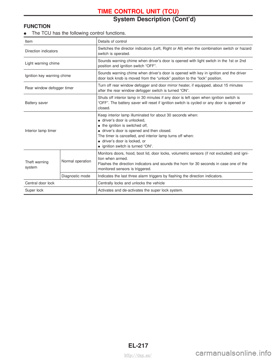
FUNCTION
IThe TCU has the following control functions.
Item Details of control
Direction indicators Switches the director indicators (Left, Right or All) when the combination switch or hazard
switch is operated.
Light warning chime Sounds warning chime when driver's door is opened with light switch in the 1st or 2nd
position and ignition switch ªOFFº.
Ignition key warning chime Sounds warning chime when driver's door is opened with key in ignition and the driver
door lock knob is moved from the ªunlockº position to the ªlockº position.
Rear window defogger timer Turn off rear window defogger and door mirror heater, if equipped, about 15 minutes
after the rear window defogger switch is turned ªONº.
Battery saver Shuts off interior lamp in 30 minutes if any door is left open when ignition switch is
ªOFFº. The battery saver will reset if ignition switch is cycled or any door is opened or
closed.
Interior lamp timer Keep interior lamp illuminated for about 30 seconds when:
I
driver's door is unlocked,
I the ignition is switched off,
I driver's door is opened and then closed.
The timer is cancelled, and interior lamp turns off when:
I driver's door is locked, or
I ignition switch is turned ªONº.
Theft warning
system Normal operationMonitors doors, hood, boot lid, door locks, volumetric sensors (if not excluded) and igni-
tion when armed.
Flashes the direction indicators and sounds the horn for 30 seconds in case one of the
monitored sensors is triggered.
Diagnostic mode Indicates the last three alarm triggers by flashing the direction indicators.
Central door lock Centrally locks and unlocks the vehicle
Super lock Activates and de-activates the super lock system.
TIME CONTROL UNIT (TCU)
System Description (Cont'd)
EL-217
http://vnx.su/