2004 NISSAN TERRANO key
[x] Cancel search: keyPage 1729 of 1833
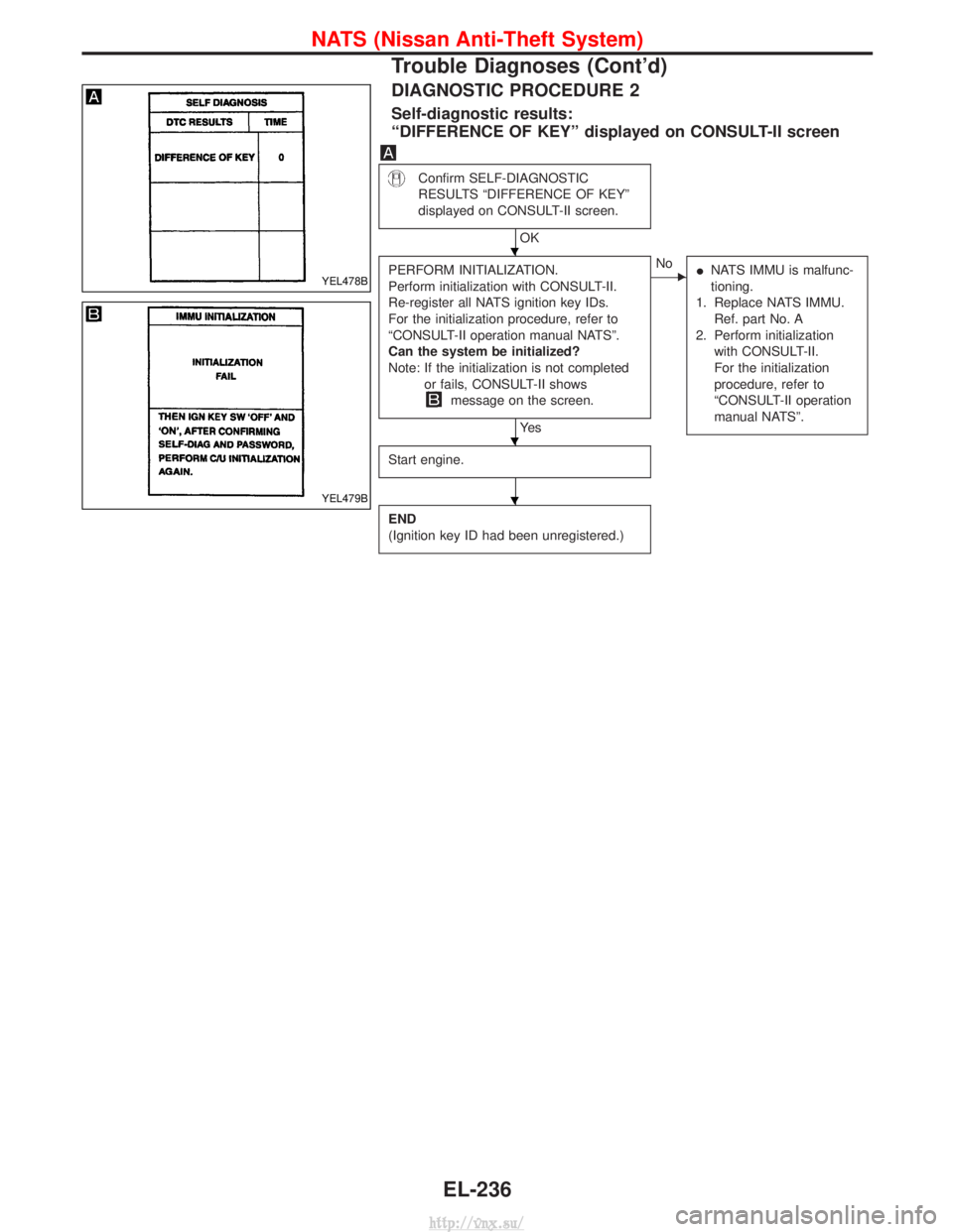
DIAGNOSTIC PROCEDURE 2
Self-diagnostic results:
ªDIFFERENCE OF KEYº displayed on CONSULT-II screen
Confirm SELF-DIAGNOSTIC
RESULTS ªDIFFERENCE OF KEYº
displayed on CONSULT-II screen.
OK
PERFORM INITIALIZATION.
Perform initialization with CONSULT-II.
Re-register all NATS ignition key IDs.
For the initialization procedure, refer to
ªCONSULT-II operation manual NATSº.
Can the system be initialized?
Note: If the initialization is not completed or fails, CONSULT-II shows
message on the screen.
Ye s
ENo INATS IMMU is malfunc-
tioning.
1. Replace NATS IMMU. Ref. part No. A
2. Perform initialization with CONSULT-II.
For the initialization
procedure, refer to
ªCONSULT-II operation
manual NATSº.
Start engine.
END
(Ignition key ID had been unregistered.)
YEL478B
YEL479B
H
H
H
NATS (Nissan Anti-Theft System)
Trouble Diagnoses (Cont'd)
EL-236
http://vnx.su/
Page 1730 of 1833
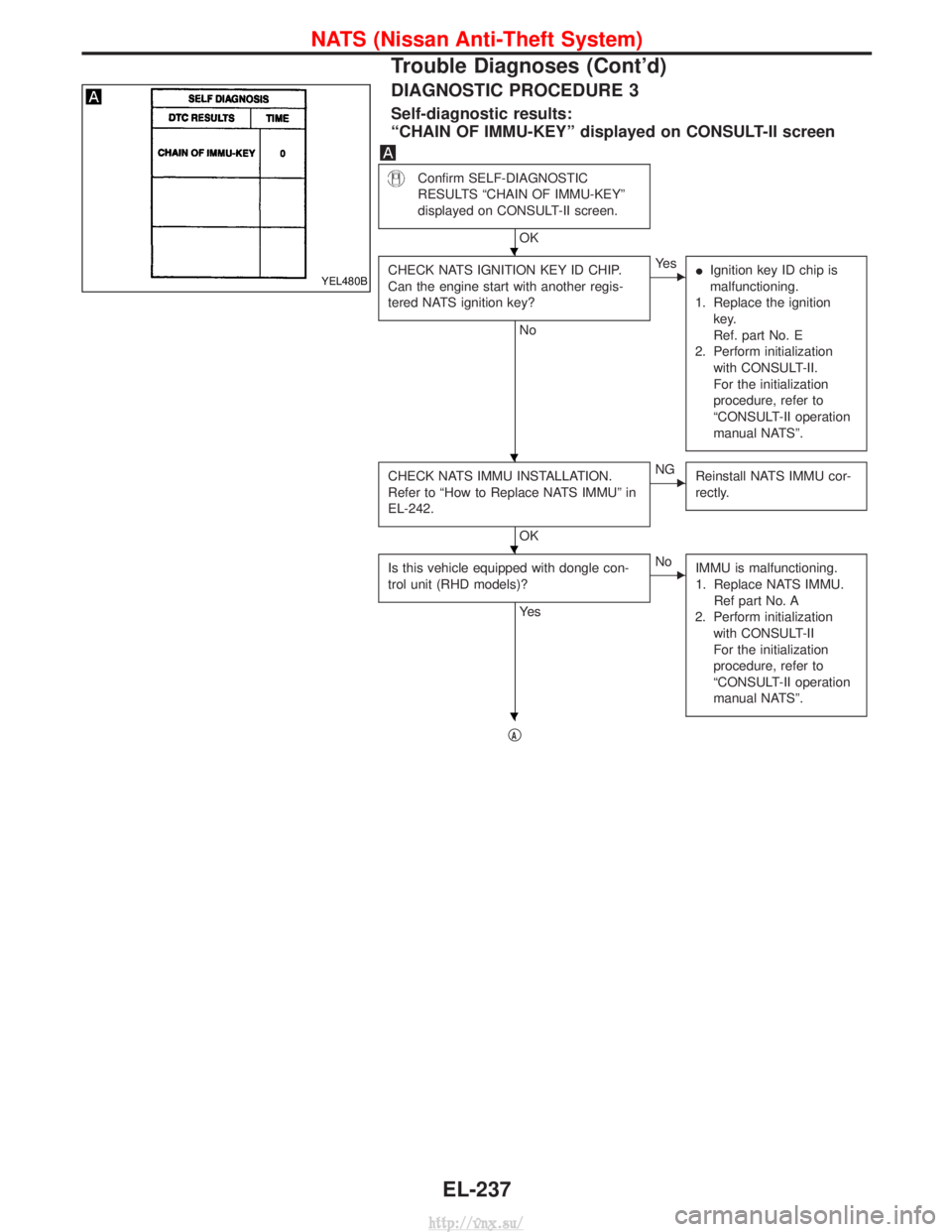
DIAGNOSTIC PROCEDURE 3
Self-diagnostic results:
ªCHAIN OF IMMU-KEYº displayed on CONSULT-II screen
Confirm SELF-DIAGNOSTIC
RESULTS ªCHAIN OF IMMU-KEYº
displayed on CONSULT-II screen.
OK
CHECK NATS IGNITION KEY ID CHIP.
Can the engine start with another regis-
tered NATS ignition key?
No
EYe s IIgnition key ID chip is
malfunctioning.
1. Replace the ignition key.
Ref. part No. E
2. Perform initialization with CONSULT-II.
For the initialization
procedure, refer to
ªCONSULT-II operation
manual NATSº.
CHECK NATS IMMU INSTALLATION.
Refer to ªHow to Replace NATS IMMUº in
EL-242.
OK
ENG Reinstall NATS IMMU cor-
rectly.
Is this vehicle equipped with dongle con-
trol unit (RHD models)?
Ye s
ENoIMMU is malfunctioning.
1. Replace NATS IMMU.
Ref part No. A
2. Perform initialization with CONSULT-II
For the initialization
procedure, refer to
ªCONSULT-II operation
manual NATSº.
qA
YEL480B
H
H
H
H
NATS (Nissan Anti-Theft System)
Trouble Diagnoses (Cont'd)
EL-237
http://vnx.su/
Page 1732 of 1833
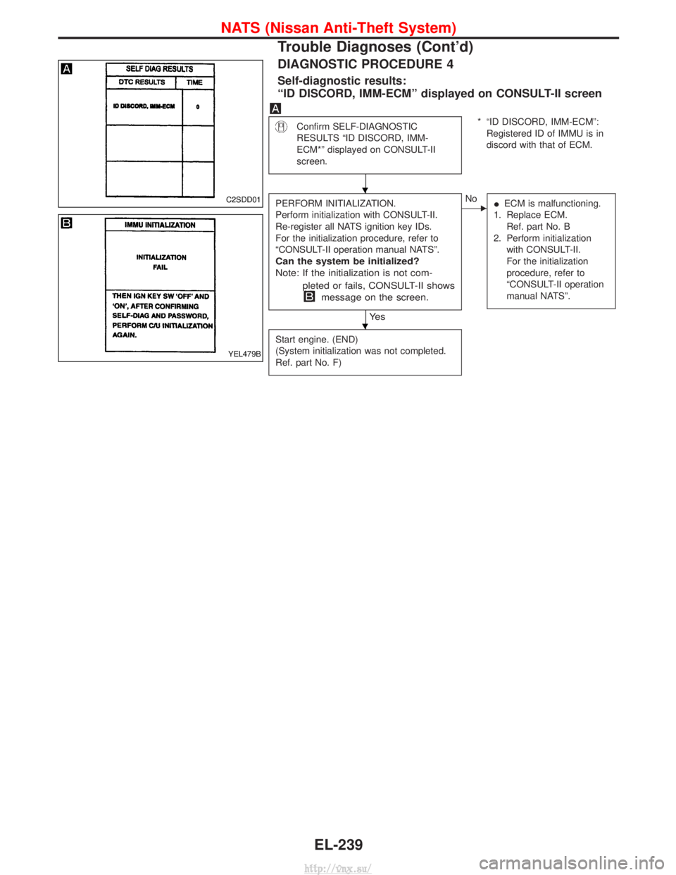
DIAGNOSTIC PROCEDURE 4
Self-diagnostic results:
ªID DISCORD, IMM-ECMº displayed on CONSULT-II screen
Confirm SELF-DIAGNOSTIC
RESULTS ªID DISCORD, IMM-
ECM*º displayed on CONSULT-II
screen.* ªID DISCORD, IMM-ECMº:Registered ID of IMMU is in
discord with that of ECM.
PERFORM INITIALIZATION.
Perform initialization with CONSULT-II.
Re-register all NATS ignition key IDs.
For the initialization procedure, refer to
ªCONSULT-II operation manual NATSº.
Can the system be initialized?
Note: If the initialization is not com- pleted or fails, CONSULT-II shows
message on the screen.
Ye s
ENo IECM is malfunctioning.
1. Replace ECM. Ref. part No. B
2. Perform initialization with CONSULT-II.
For the initialization
procedure, refer to
ªCONSULT-II operation
manual NATSº.
Start engine. (END)
(System initialization was not completed.
Ref. part No. F)
C2SDD01
YEL479B
H
H
NATS (Nissan Anti-Theft System)
Trouble Diagnoses (Cont'd)
EL-239
http://vnx.su/
Page 1733 of 1833
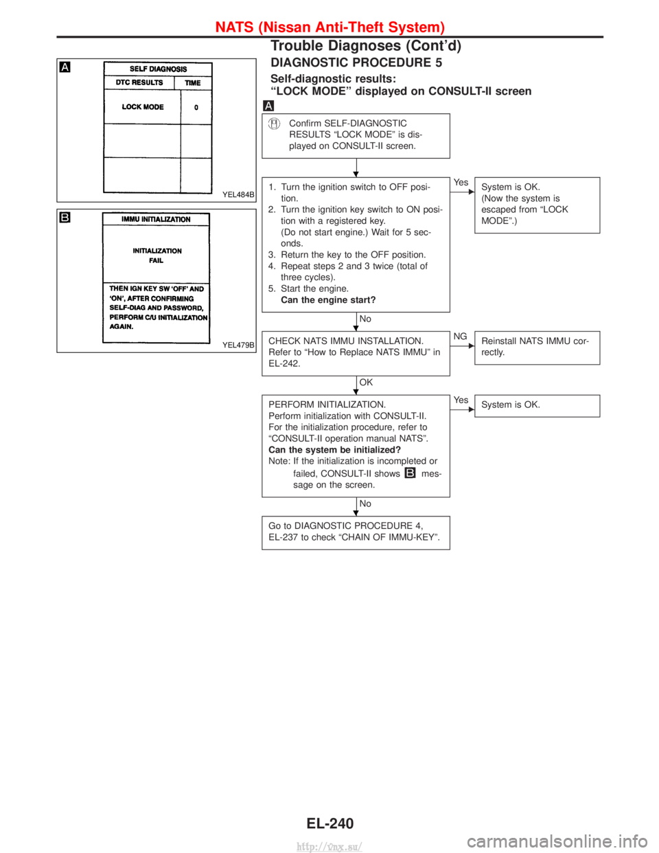
DIAGNOSTIC PROCEDURE 5
Self-diagnostic results:
ªLOCK MODEº displayed on CONSULT-II screen
Confirm SELF-DIAGNOSTIC
RESULTS ªLOCK MODEº is dis-
played on CONSULT-II screen.
1. Turn the ignition switch to OFF posi-tion.
2. Turn the ignition key switch to ON posi- tion with a registered key.
(Do not start engine.) Wait for 5 sec-
onds.
3. Return the key to the OFF position.
4. Repeat steps 2 and 3 twice (total of three cycles).
5. Start the engine. Can the engine start?
No
EYe s System is OK.
(Now the system is
escaped from ªLOCK
MODEº.)
CHECK NATS IMMU INSTALLATION.
Refer to ªHow to Replace NATS IMMUº in
EL-242.
OK
ENGReinstall NATS IMMU cor-
rectly.
PERFORM INITIALIZATION.
Perform initialization with CONSULT-II.
For the initialization procedure, refer to
ªCONSULT-II operation manual NATSº.
Can the system be initialized?
Note: If the initialization is incompleted or
failed, CONSULT-II shows
mes-
sage on the screen.
No
EYe s System is OK.
Go to DIAGNOSTIC PROCEDURE 4,
EL-237 to check ªCHAIN OF IMMU-KEYº.
YEL484B
YEL479B
H
H
H
H
NATS (Nissan Anti-Theft System)
Trouble Diagnoses (Cont'd)
EL-240
http://vnx.su/
Page 1735 of 1833
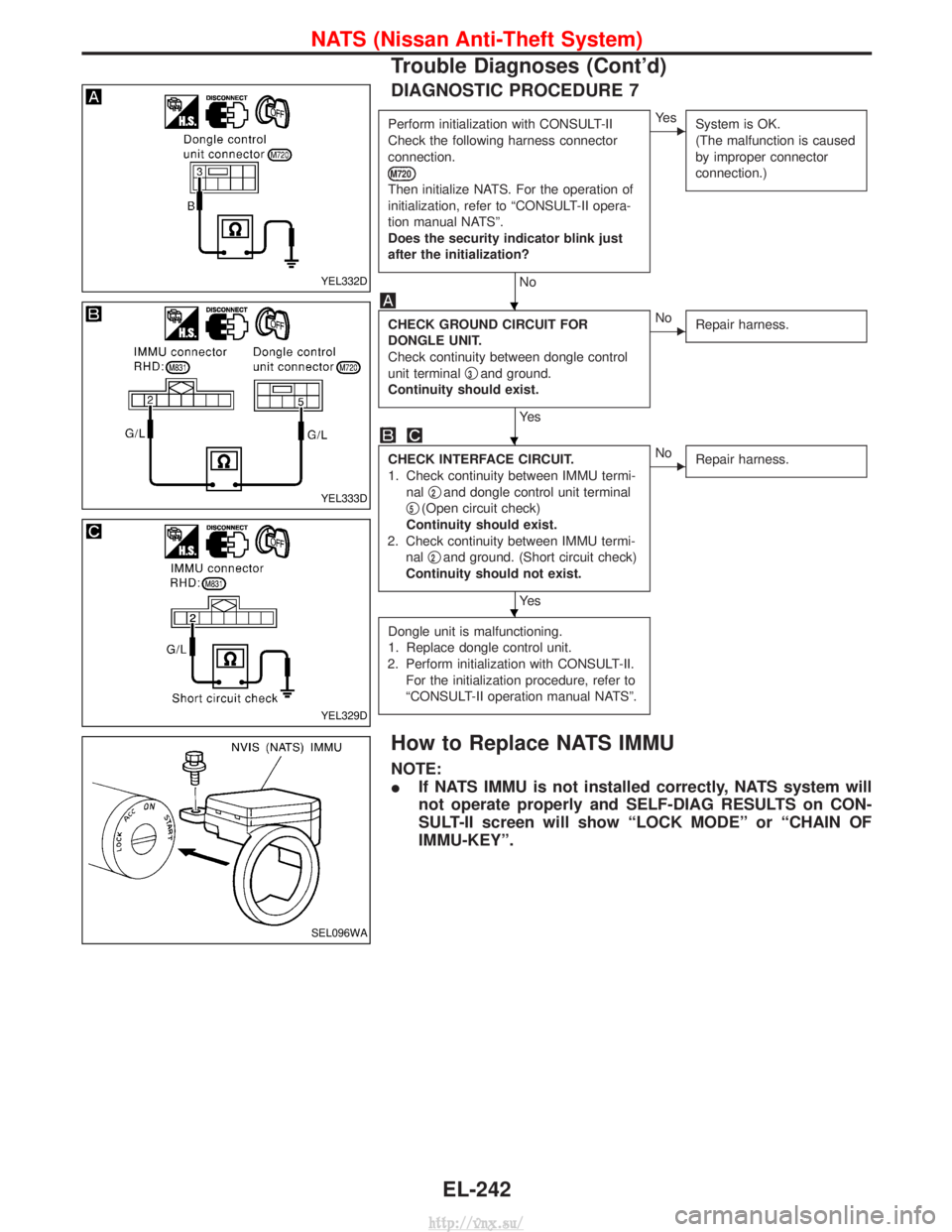
DIAGNOSTIC PROCEDURE 7
Perform initialization with CONSULT-II
Check the following harness connector
connection.
M720
Then initialize NATS. For the operation of
initialization, refer to ªCONSULT-II opera-
tion manual NATSº.
Does the security indicator blink just
after the initialization?
No
EYe sSystem is OK.
(The malfunction is caused
by improper connector
connection.)
CHECK GROUND CIRCUIT FOR
DONGLE UNIT.
Check continuity between dongle control
unit terminal q
3and ground.
Continuity should exist.
Ye s
ENo Repair harness.
CHECK INTERFACE CIRCUIT.
1. Check continuity between IMMU termi-
nal q
2and dongle control unit terminal
q
5(Open circuit check)
Continuity should exist.
2. Check continuity between IMMU termi- nal q
2and ground. (Short circuit check)
Continuity should not exist.
Ye s
ENo Repair harness.
Dongle unit is malfunctioning.
1. Replace dongle control unit.
2. Perform initialization with CONSULT-II. For the initialization procedure, refer to
ªCONSULT-II operation manual NATSº.
How to Replace NATS IMMU
NOTE:
I If NATS IMMU is not installed correctly, NATS system will
not operate properly and SELF-DIAG RESULTS on CON-
SULT-II screen will show ªLOCK MODEº or ªCHAIN OF
IMMU-KEYº.
YEL332D
YEL333D
YEL329D
SEL096WA
H
H
H
NATS (Nissan Anti-Theft System)
Trouble Diagnoses (Cont'd)
EL-242
http://vnx.su/
Page 1738 of 1833
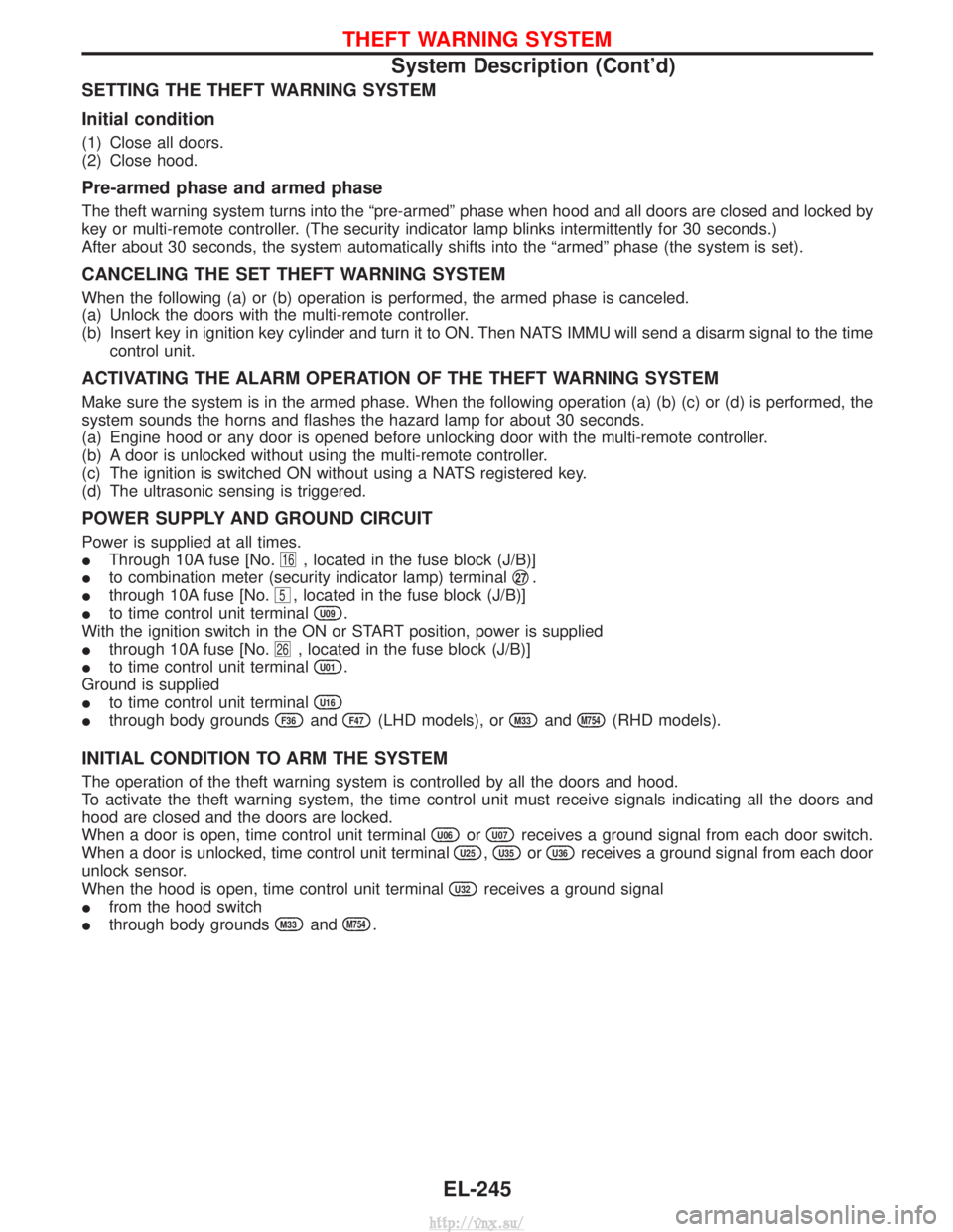
SETTING THE THEFT WARNING SYSTEM
Initial condition
(1) Close all doors.
(2) Close hood.
Pre-armed phase and armed phase
The theft warning system turns into the ªpre-armedº phase when hood and all doors are closed and locked by
key or multi-remote controller. (The security indicator lamp blinks intermittently for 30 seconds.)
After about 30 seconds, the system automatically shifts into the ªarmedº phase (the system is set).
CANCELING THE SET THEFT WARNING SYSTEM
When the following (a) or (b) operation is performed, the armed phase is canceled.
(a) Unlock the doors with the multi-remote controller.
(b) Insert key in ignition key cylinder and turn it to ON. Then NATS IMMU will send a disarm signal to the timecontrol unit.
ACTIVATING THE ALARM OPERATION OF THE THEFT WARNING SYSTEM
Make sure the system is in the armed phase. When the following operation (a) (b) (c) or (d) is performed, the
system sounds the horns and flashes the hazard lamp for about 30 seconds.
(a) Engine hood or any door is opened before unlocking door with the multi-remote controller.
(b) A door is unlocked without using the multi-remote controller.
(c) The ignition is switched ON without using a NATS registered key.
(d) The ultrasonic sensing is triggered.
POWER SUPPLY AND GROUND CIRCUIT
Power is supplied at all times.
IThrough 10A fuse [No.
16, located in the fuse block (J/B)]
I to combination meter (security indicator lamp) terminal q
27.
I through 10A fuse [No.
5, located in the fuse block (J/B)]
I to time control unit terminal
U09.
With the ignition switch in the ON or START position, power is supplied
I through 10A fuse [No.
26, located in the fuse block (J/B)]
I to time control unit terminal
U01.
Ground is supplied
I to time control unit terminal
U16
Ithrough body groundsF36andF47(LHD models), orM33andM754(RHD models).
INITIAL CONDITION TO ARM THE SYSTEM
The operation of the theft warning system is controlled by all the doors and hood.
To activate the theft warning system, the time control unit must receive signals indicating all the doors and
hood are closed and the doors are locked.
When a door is open, time control unit terminal
U06orU07receives a ground signal from each door switch.
When a door is unlocked, time control unit terminal
U25,U35orU36receives a ground signal from each door
unlock sensor.
When the hood is open, time control unit terminal
U32receives a ground signal
I from the hood switch
I through body grounds
M33andM754.
THEFT WARNING SYSTEM
System Description (Cont'd)
EL-245
http://vnx.su/
Page 1739 of 1833
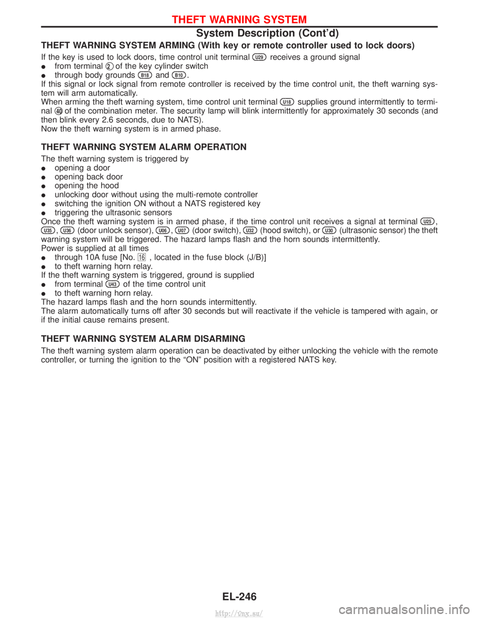
THEFT WARNING SYSTEM ARMING (With key or remote controller used to lock doors)
If the key is used to lock doors, time control unit terminalU29receives a ground signal
I from terminal q
2of the key cylinder switch
I through body grounds
B18andB10.
If this signal or lock signal from remote controller is received by the time control unit, the theft warning sys-
tem will arm automatically.
When arming the theft warning system, time control unit terminal
U18supplies ground intermittently to termi-
nal q
40of the combination meter. The security lamp will blink intermittently for approximately 30 seconds (and
then blink every 2.6 seconds, due to NATS).
Now the theft warning system is in armed phase.
THEFT WARNING SYSTEM ALARM OPERATION
The theft warning system is triggered by
I opening a door
I opening back door
I opening the hood
I unlocking door without using the multi-remote controller
I switching the ignition ON without a NATS registered key
I triggering the ultrasonic sensors
Once the theft warning system is in armed phase, if the time control unit receives a signal at terminal
U25,
U35,U36(door unlock sensor),U06,U07(door switch),U32(hood switch), orU30(ultrasonic sensor) the theft
warning system will be triggered. The hazard lamps flash and the horn sounds intermittently.
Power is supplied at all times
I through 10A fuse [No.
16, located in the fuse block (J/B)]
I to theft warning horn relay.
If the theft warning system is triggered, ground is supplied
I from terminal
U43of the time control unit
I to theft warning horn relay.
The hazard lamps flash and the horn sounds intermittently.
The alarm automatically turns off after 30 seconds but will reactivate if the vehicle is tampered with again, or
if the initial cause remains present.
THEFT WARNING SYSTEM ALARM DISARMING
The theft warning system alarm operation can be deactivated by either unlocking the vehicle with the remote
controller, or turning the ignition to the ªONº position with a registered NATS key.
THEFT WARNING SYSTEM
System Description (Cont'd)
EL-246
http://vnx.su/
Page 1758 of 1833
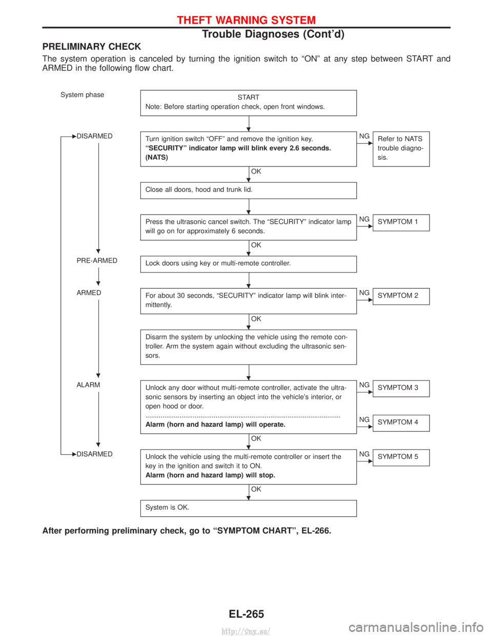
PRELIMINARY CHECK
The system operation is canceled by turning the ignition switch to ªONº at any step between START and
ARMED in the following flow chart.
System phaseSTART
Note: Before starting operation check, open front windows.
EDISARMED Turn ignition switch ªOFFº and remove the ignition key.
ªSECURITYº indicator lamp will blink every 2.6 seconds.
(NATS)
OK
ENGRefer to NATS
trouble diagno-
sis.
Close all doors, hood and trunk lid.
Press the ultrasonic cancel switch. The ªSECURITYº indicator lamp
will go on for approximately 6 seconds.
OK
ENGSYMPTOM 1
PRE-ARMED Lock doors using key or multi-remote controller.
ARMEDFor about 30 seconds, ªSECURITYº indicator lamp will blink inter-
mittently.
OK
ENGSYMPTOM 2
Disarm the system by unlocking the vehicle using the remote con-
troller. Arm the system again without excluding the ultrasonic sen-
sors.
ALARM Unlock any door without multi-remote controller, activate the ultra-
sonic sensors by inserting an object into the vehicle's interior, or
open hood or door.
........................................................................\
...............................
Alarm (horn and hazard lamp) will operate.
OK
ENGSYMPTOM 3
ENGSYMPTOM 4
EDISARMED Unlock the vehicle using the multi-remote controller or insert the
key in the ignition and switch it to ON.
Alarm (horn and hazard lamp) will stop.
OK
ENGSYMPTOM 5
System is OK.
After performing preliminary check, go to ªSYMPTOM CHARTº, EL-266.
H
H
H
HH
HH
H
HH
HH
H
THEFT WARNING SYSTEM
Trouble Diagnoses (Cont'd)
EL-265
http://vnx.su/