Page 926 of 1833
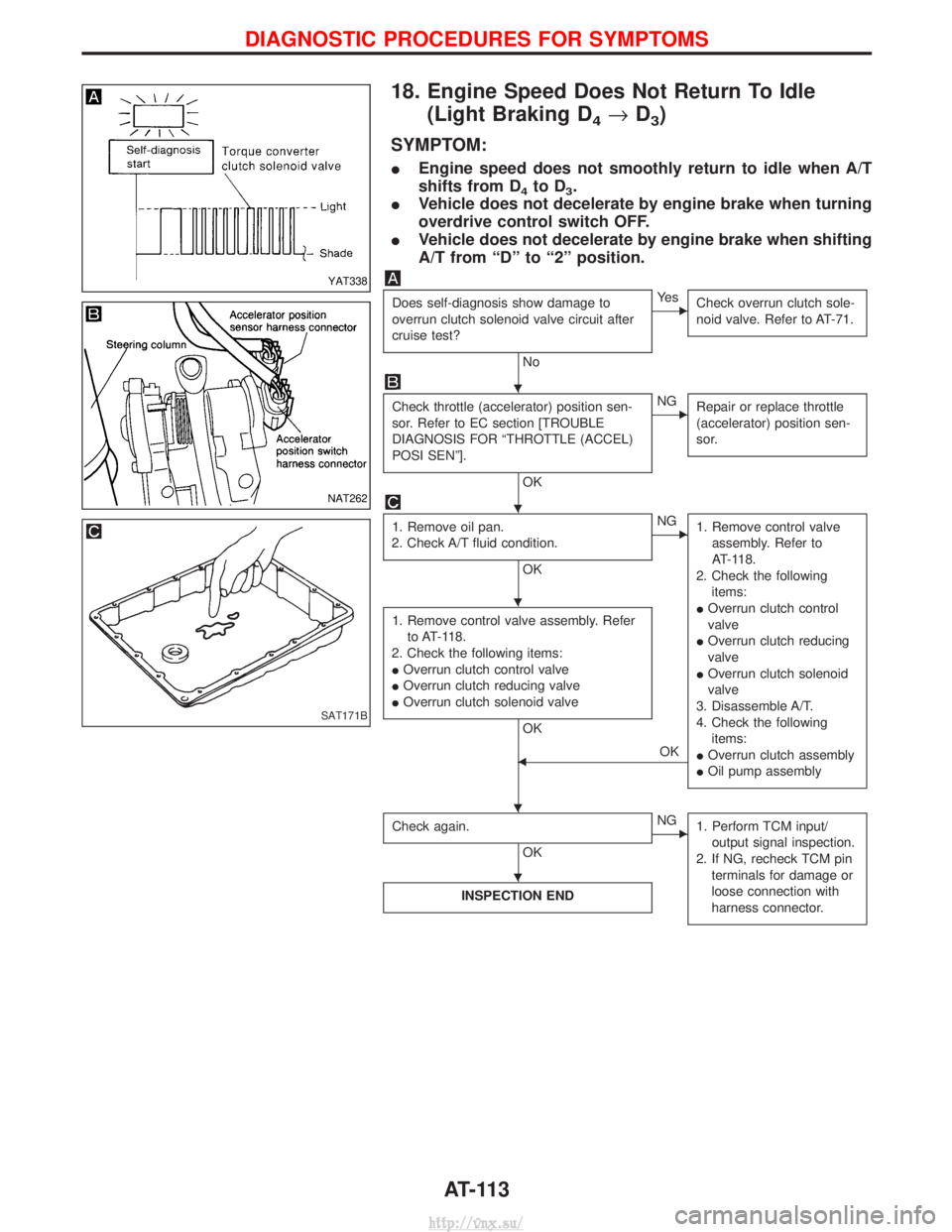
18. Engine Speed Does Not Return To Idle(Light Braking D
4®D3)
SYMPTOM:
I Engine speed does not smoothly return to idle when A/T
shifts from D
4to D3.
I Vehicle does not decelerate by engine brake when turning
overdrive control switch OFF.
I Vehicle does not decelerate by engine brake when shifting
A/T from ªDº to ª2º position.
Does self-diagnosis show damage to
overrun clutch solenoid valve circuit after
cruise test?
No
EYe s
Check overrun clutch sole-
noid valve. Refer to AT-71.
Check throttle (accelerator) position sen-
sor. Refer to EC section [TROUBLE
DIAGNOSIS FOR ªTHROTTLE (ACCEL)
POSI SENº].
OK
ENGRepair or replace throttle
(accelerator) position sen-
sor.
1. Remove oil pan.
2. Check A/T fluid condition.
OK
ENG 1. Remove control valve
assembly. Refer to
AT-118.
2. Check the following items:
I Overrun clutch control
valve
I Overrun clutch reducing
valve
I Overrun clutch solenoid
valve
3. Disassemble A/T.
4. Check the following items:
I Overrun clutch assembly
I Oil pump assembly
1. Remove control valve assembly. Refer
to AT-118.
2. Check the following items:
I Overrun clutch control valve
I Overrun clutch reducing valve
I Overrun clutch solenoid valve
OK
FOK
Check again.
OK
ENG 1. Perform TCM input/
output signal inspection.
2. If NG, recheck TCM pin terminals for damage or
loose connection with
harness connector.
INSPECTION END
YAT338
NAT262
SAT171B
H
H
H
HH
H
DIAGNOSTIC PROCEDURES FOR SYMPTOMS
AT-113
http://vnx.su/
Page 930 of 1833
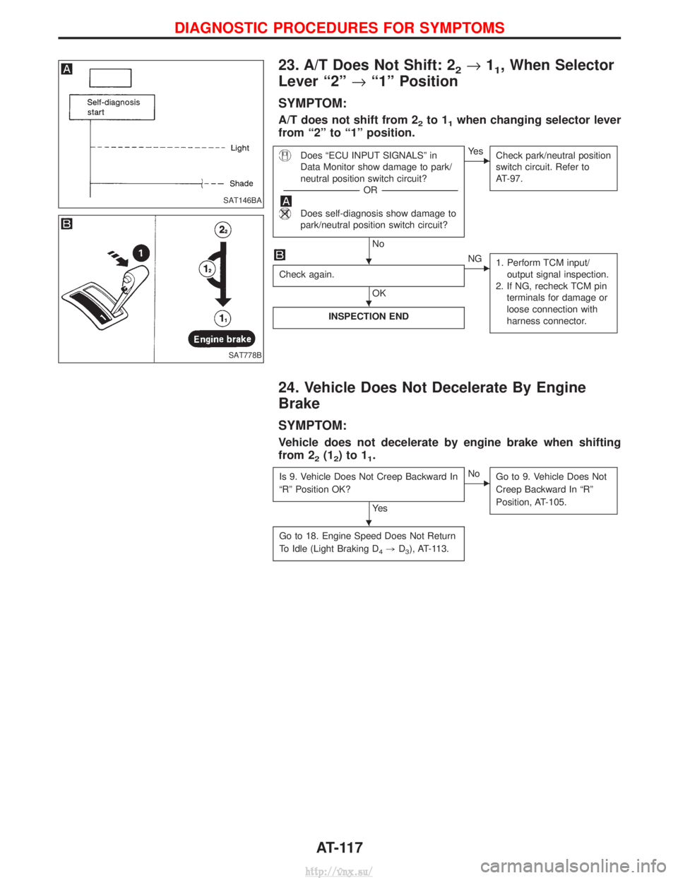
23. A/T Does Not Shift: 22®11, When Selector
Lever ª2º ®ª1º Position
SYMPTOM:
A/T does not shift from 22to 11when changing selector lever
from ª2º to ª1º position.
Does ªECU INPUT SIGNALSº in
Data Monitor show damage to park/
neutral position switch circuit?
---------------------------------------------------------------------------------------------------------------------- -OR -----------------------------------------------------------------------------------------------------------------------
Does self-diagnosis show damage to
park/neutral position switch circuit?
No
EYe s
Check park/neutral position
switch circuit. Refer to
AT-97.
Check again.
OK
ENG1. Perform TCM input/
output signal inspection.
2. If NG, recheck TCM pin terminals for damage or
loose connection with
harness connector.
INSPECTION END
24. Vehicle Does Not Decelerate By Engine
Brake
SYMPTOM:
Vehicle does not decelerate by engine brake when shifting
from 2
2(12)to11.
Is 9. Vehicle Does Not Creep Backward In
ªRº Position OK?
Ye s
ENo Go to 9. Vehicle Does Not
Creep Backward In ªRº
Position, AT-105.
Go to 18. Engine Speed Does Not Return
To Idle (Light Braking D
4,D3), AT-113.
SAT146BA
SAT778B
H
H
H
DIAGNOSTIC PROCEDURES FOR SYMPTOMS
AT-117
http://vnx.su/
Page 932 of 1833
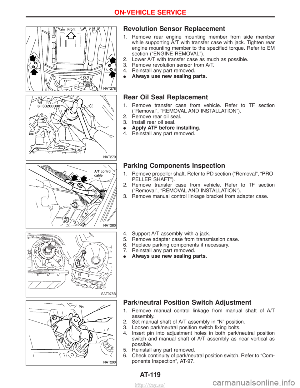
Revolution Sensor Replacement
1. Remove rear engine mounting member from side memberwhile supporting A/T with transfer case with jack. Tighten rear
engine mounting member to the specified torque. Refer to EM
section (ªENGINE REMOVALº).
2. Lower A/T with transfer case as much as possible.
3. Remove revolution sensor from A/T.
4. Reinstall any part removed.
I Always use new sealing parts.
Rear Oil Seal Replacement
1. Remove transfer case from vehicle. Refer to TF section
(ªRemovalº, ªREMOVAL AND INSTALLATIONº).
2. Remove rear oil seal.
3. Install rear oil seal.
I Apply ATF before installing.
4. Reinstall any part removed.
Parking Components Inspection
1. Remove propeller shaft. Refer to PD section (ªRemovalº, ªPRO- PELLER SHAFTº).
2. Remove transfer case from vehicle. Refer to TF section (ªRemovalº, ªREMOVAL AND INSTALLATIONº).
3. Remove manual control linkage bracket from adapter case.
4. Support A/T assembly with a jack.
5. Remove adapter case from transmission case.
6. Replace parking components if necessary.
7. Reinstall any part removed.
I Always use new sealing parts.
Park/neutral Position Switch Adjustment
1. Remove manual control linkage from manual shaft of A/T
assembly.
2. Set manual shaft of A/T assembly in ªNº position.
3. Loosen park/neutral position switch fixing bolts.
4. Insert pin into adjustment holes in both park/neutral position switch and manual shaft of A/T assembly as near vertical as
possible.
5. Reinstall any part removed.
6. Check continuity of park/neutral position switch. Refer to ªCom- ponents Inspectionº, AT-97.
NAT278
NAT279
NAT280
SAT078B
NAT290
ON-VEHICLE SERVICE
AT-119
http://vnx.su/
Page 935 of 1833
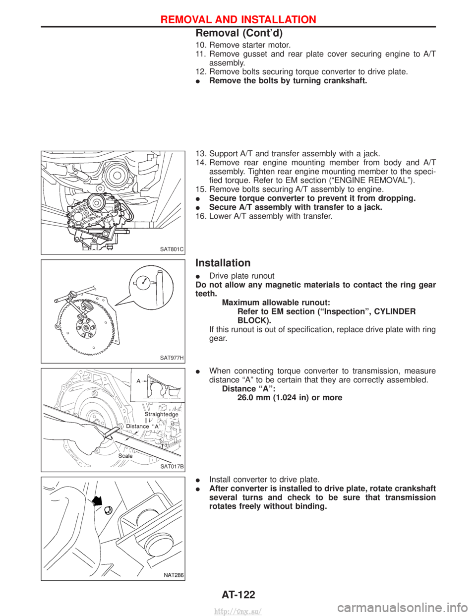
10. Remove starter motor.
11. Remove gusset and rear plate cover securing engine to A/Tassembly.
12. Remove bolts securing torque converter to drive plate.
I Remove the bolts by turning crankshaft.
13. Support A/T and transfer assembly with a jack.
14. Remove rear engine mounting member from body and A/T assembly. Tighten rear engine mounting member to the speci-
fied torque. Refer to EM section (ªENGINE REMOVALº).
15. Remove bolts securing A/T assembly to engine.
I Secure torque converter to prevent it from dropping.
I Secure A/T assembly with transfer to a jack.
16. Lower A/T assembly with transfer.
Installation
I Drive plate runout
Do not allow any magnetic materials to contact the ring gear
teeth. Maximum allowable runout:Refer to EM section (ªInspectionº, CYLINDER
BLOCK).
If this runout is out of specification, replace drive plate with ring
gear.
I When connecting torque converter to transmission, measure
distance ªAº to be certain that they are correctly assembled.
Distance ªAº: 26.0 mm (1.024 in) or more
I Install converter to drive plate.
I After converter is installed to drive plate, rotate crankshaft
several turns and check to be sure that transmission
rotates freely without binding.
SAT801C
SAT977H
SAT017B
NAT286
REMOVAL AND INSTALLATION
Removal (Cont'd)
AT-122
http://vnx.su/
Page 936 of 1833
ITighten bolts securing transmission.
Bolt No. Tightening torque
N×m (kg-m, ft-lb) Bolt length ªº
mm (in)
q
139 - 49 (4.0 - 5.0, 29 - 36) 58.0 (2.28)
q
229 - 39 (3.0 - 4.0, 22 - 29) 90.0 (3.54)
q
318 - 22 (1.8 - 2.2, 13 - 16) 16.0 (0.63)
q
43 - 4 (0.3 - 0.4, 2.2 - 2.9) 12.0 (0.47)
q
529 - 39 (3.0 - 4.0, 22 - 29) 35.0 (1.38)
IReinstall any part removed.
I Check fluid level in transmission.
I Move selector lever through all positions to be sure that trans-
mission operates correctly.
With parking brake applied, rotate engine at idling. Move selec-
tor lever through ªNº to ªDº, to ª2º, to ª1º and to ªRº positions.
A slight shock should be felt by hand gripping selector each
time transmission is shifted.
I Perform road test. Refer to ªROAD TESTº, AT-32.NAT287
SAT638A
REMOVAL AND INSTALLATION
Installation (Cont'd)
AT-123
http://vnx.su/
Page 942 of 1833
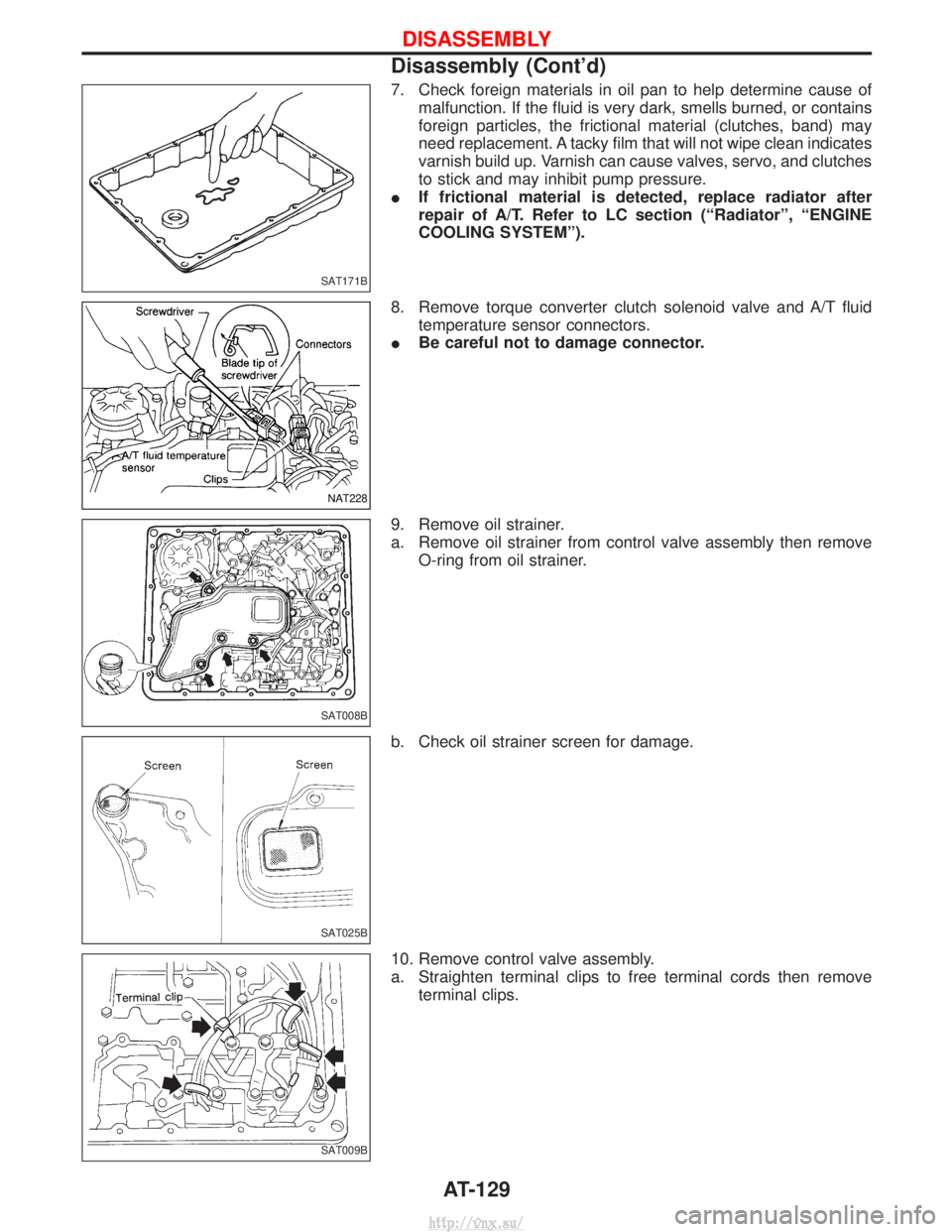
7. Check foreign materials in oil pan to help determine cause ofmalfunction. If the fluid is very dark, smells burned, or contains
foreign particles, the frictional material (clutches, band) may
need replacement. A tacky film that will not wipe clean indicates
varnish build up. Varnish can cause valves, servo, and clutches
to stick and may inhibit pump pressure.
I If frictional material is detected, replace radiator after
repair of A/T. Refer to LC section (ªRadiatorº, ªENGINE
COOLING SYSTEMº).
8. Remove torque converter clutch solenoid valve and A/T fluid temperature sensor connectors.
I Be careful not to damage connector.
9. Remove oil strainer.
a. Remove oil strainer from control valve assembly then remove O-ring from oil strainer.
b. Check oil strainer screen for damage.
10. Remove control valve assembly.
a. Straighten terminal clips to free terminal cords then remove terminal clips.
SAT171B
NAT228
SAT008B
SAT025B
SAT009B
DISASSEMBLY
Disassembly (Cont'd)
AT-129
http://vnx.su/
Page 1094 of 1833
CAUTION:
Do not run engine when one rear wheel is off the ground.
Preparation for Disassembly
CHECKING DIFFERENTIAL TORQUE
Measure differential torque with Tool.
If it is not within the specifications, inspect components of limited
slip differential.Differential torque:353 - 392 N×m (36 - 40 kg-m, 260 - 289 ft-lb)
Assembly: KV38105250
Tool number: q
AKV38105210
q
BKV38105220
YPD025
SPD415
LIMITED SLIP DIFFERENTIAL (C200)
PD-43
http://vnx.su/
Page 1113 of 1833
(1) When installing each rubber part, final tightening must be car-ried out under unladen condition * with tires on ground.
* Fuel, radiator coolant and engine oil full. Spare tire, jack,hand tools and mats in designated positions.
(2) When removing each suspension part, check wheel alignment and adjust if necessary.
(3) Use Tool when removing or installing brake tubes.
SBR820B
PRECAUTIONS
FA-2
http://vnx.su/