2004 NISSAN TERRANO check engine
[x] Cancel search: check enginePage 1731 of 1833

qA
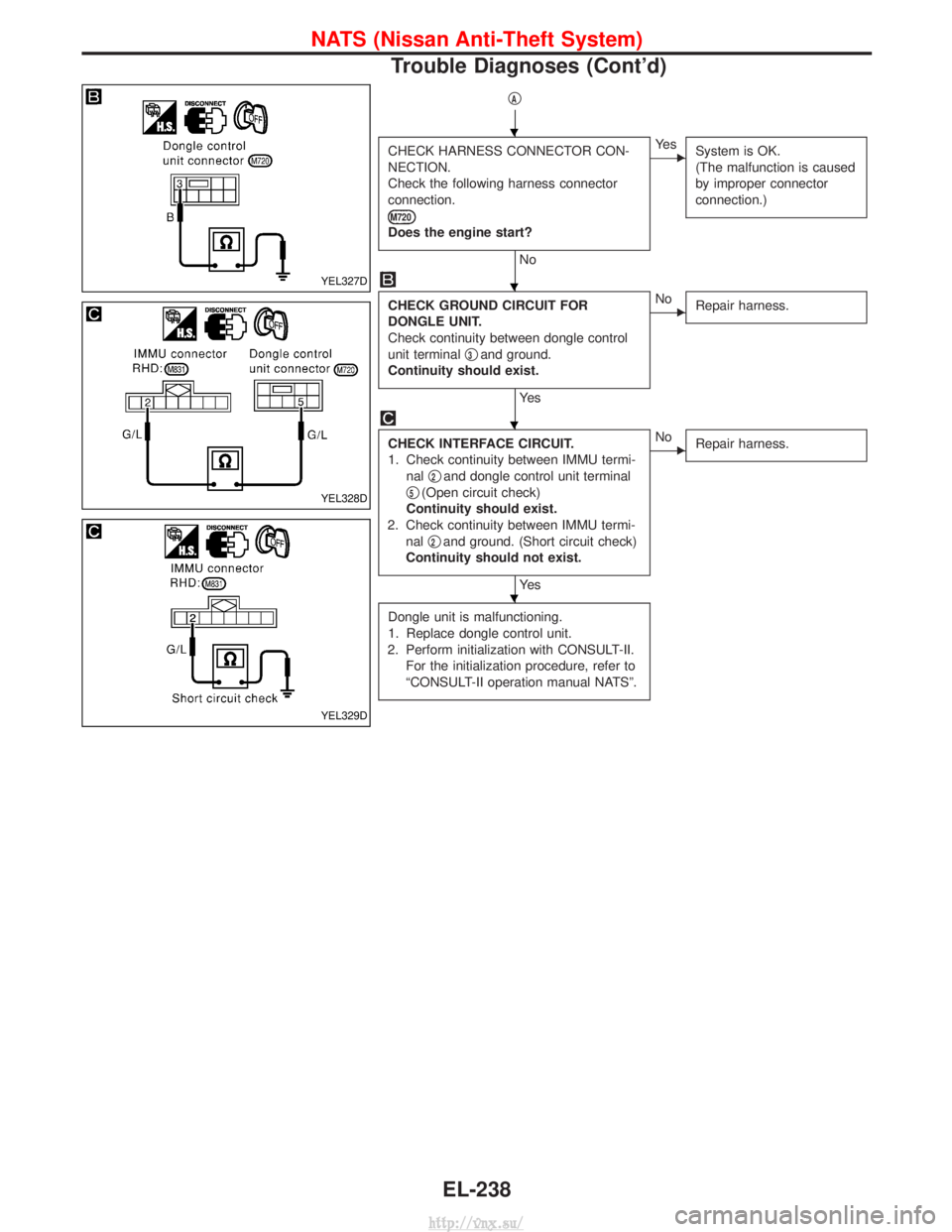
CHECK HARNESS CONNECTOR CON-
NECTION.
Check the following harness connector
connection.
M720
Does the engine start?
No
EYe sSystem is OK.
(The malfunction is caused
by improper connector
connection.)
CHECK GROUND CIRCUIT FOR
DONGLE UNIT.
Check continuity between dongle control
unit terminal q
3and ground.
Continuity should exist.
Ye s
ENo Repair harness.
CHECK INTERFACE CIRCUIT.
1. Check continuity between IMMU termi-
nal q
2and dongle control unit terminal
q
5(Open circuit check)
Continuity should exist.
2. Check continuity between IMMU termi- nal q
2and ground. (Short circuit check)
Continuity should not exist.
Ye s
ENo Repair harness.
Dongle unit is malfunctioning.
1. Replace dongle control unit.
2. Perform initialization with CONSULT-II. For the initialization procedure, refer to
ªCONSULT-II operation manual NATSº.
YEL327D
YEL328D
YEL329D
H
H
H
H
NATS (Nissan Anti-Theft System)
Trouble Diagnoses (Cont'd)
EL-238
http://vnx.su/
Page 1733 of 1833

DIAGNOSTIC PROCEDURE 5
Self-diagnostic results:
ªLOCK MODEº displayed on CONSULT-II screen
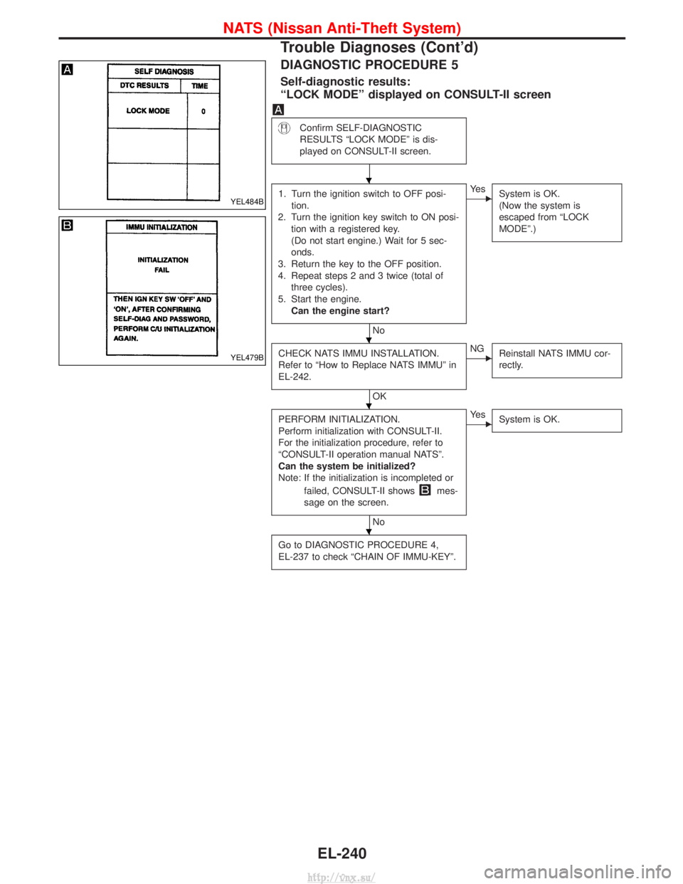
Confirm SELF-DIAGNOSTIC
RESULTS ªLOCK MODEº is dis-
played on CONSULT-II screen.
1. Turn the ignition switch to OFF posi-tion.
2. Turn the ignition key switch to ON posi- tion with a registered key.
(Do not start engine.) Wait for 5 sec-
onds.
3. Return the key to the OFF position.
4. Repeat steps 2 and 3 twice (total of three cycles).
5. Start the engine. Can the engine start?
No
EYe s System is OK.
(Now the system is
escaped from ªLOCK
MODEº.)
CHECK NATS IMMU INSTALLATION.
Refer to ªHow to Replace NATS IMMUº in
EL-242.
OK
ENGReinstall NATS IMMU cor-
rectly.
PERFORM INITIALIZATION.
Perform initialization with CONSULT-II.
For the initialization procedure, refer to
ªCONSULT-II operation manual NATSº.
Can the system be initialized?
Note: If the initialization is incompleted or
failed, CONSULT-II shows
mes-
sage on the screen.
No
EYe s System is OK.
Go to DIAGNOSTIC PROCEDURE 4,
EL-237 to check ªCHAIN OF IMMU-KEYº.
YEL484B
YEL479B
H
H
H
H
NATS (Nissan Anti-Theft System)
Trouble Diagnoses (Cont'd)
EL-240
http://vnx.su/
Page 1734 of 1833

DIAGNOSTIC PROCEDURE 6
ªSECURITY INDICATOR LAMP DOES NOT LIGHT UPº
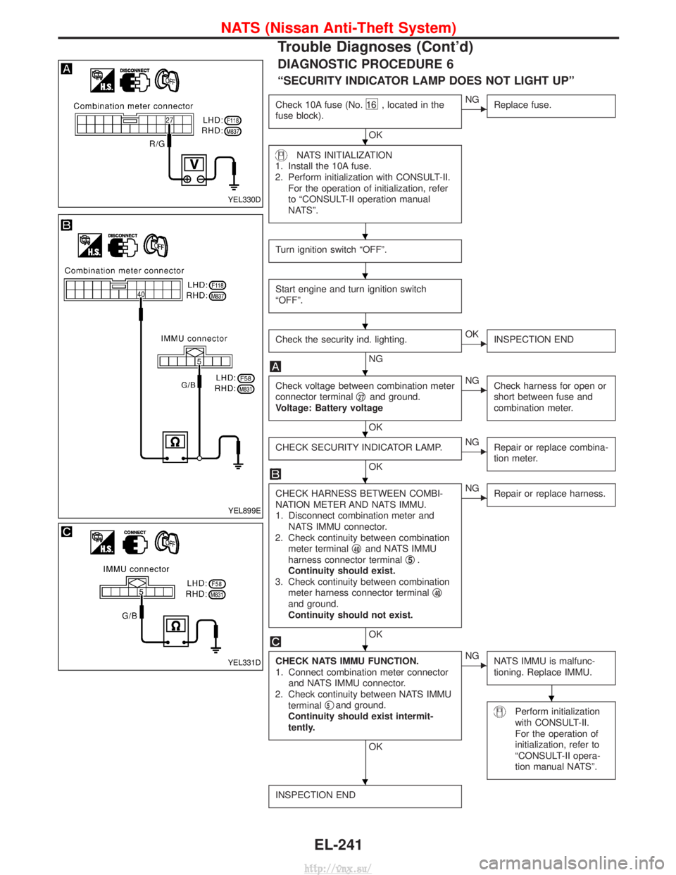
Check 10A fuse (No.16 , located in the
fuse block).
OK
ENG Replace fuse.
NATS INITIALIZATION
1. Install the 10A fuse.
2. Perform initialization with CONSULT-II. For the operation of initialization, refer
to ªCONSULT-II operation manual
NATSº.
Turn ignition switch ªOFFº.
Start engine and turn ignition switch
ªOFFº.
Check the security ind. lighting.
NG
EOK INSPECTION END
Check voltage between combination meter
connector terminal q27and ground.
Voltage: Battery voltage
OK
ENG Check harness for open or
short between fuse and
combination meter.
CHECK SECURITY INDICATOR LAMP.
OK
ENGRepair or replace combina-
tion meter.
CHECK HARNESS BETWEEN COMBI-
NATION METER AND NATS IMMU.
1. Disconnect combination meter and
NATS IMMU connector.
2. Check continuity between combination meter terminal q
40and NATS IMMU
harness connector terminal q5.
Continuity should exist.
3. Check continuity between combination meter harness connector terminal q
40and ground.
Continuity should not exist.
OK
ENG
Repair or replace harness.
CHECK NATS IMMU FUNCTION.
1. Connect combination meter connector
and NATS IMMU connector.
2. Check continuity between NATS IMMU terminal q
5and ground.
Continuity should exist intermit-
tently.
OK
ENG NATS IMMU is malfunc-
tioning. Replace IMMU.
Perform initialization
with CONSULT-II.
For the operation of
initialization, refer to
ªCONSULT-II opera-
tion manual NATSº.
INSPECTION END
YEL330D
YEL899E
YEL331D
H
H
H
H
H
H
H
H
H
H
NATS (Nissan Anti-Theft System)
Trouble Diagnoses (Cont'd)
EL-241
http://vnx.su/
Page 1830 of 1833

INT/V - Wiring diagram ................................EC-282
Intake air control valve control solenoidvalve .........................................................EC-281
Intake Air Volume .........................................EC-150
Intake door control linkage adjustment ..........HA-63
Intake manifold...............................................EM-12
Interior .............................................................BT-18
Interior lamp ..............................................EL-67, 74
Interior lamp on-off control..............................EL-73
ISO 15031-2 Terminology................................GI-34
K
Knuckle spindle ...............................................FA-20 L
License lamp ...................................................EL-49
Limited slip diff. adjustment............................PD-45
Limited slip diff. assembly ..............................PD-47
Limited slip diff. disassembly ...................PD-43, 44
Limited slip diff. inspection .............................PD-44
Line pressure solenoid valve ..........................AT-86
Line pressure test (A/T) ..........................AT-30, 201
Liquid gasket application .................................EM-3
Location of electrical units ............EL-275, 276, 278
Lock, door ...........................................BT-10, 12, 14
Low and reverse brake .................................AT-166
LSV (Load sensing valve) ..............................BR-10
Lubricants.......................................................MA-17
Lubrication circuit (engine) .........................LC-3, 20
Lubrication oil A/C (checking andadjusting) ....................................................HA-22
Lubrication oil A/C (SDS) ...............................HA-64
Lubrication-locks, hinges and hood latches ..................................................MA-36, 45
Luggage compartment trim .............................BT-18
M
MAFS - Wiring diagram..................................EC-90
MAIN - Wiring diagram...................................EC-80
Main drive gear (M/T) .....................................MT-11
Main gear (Transfer) .................................TF-10, 21
Mainshaft (M/T) ..............................................MT-11
Mainshaft (Transfer)..................................TF-10, 17
Maintenance ...........MA-5, 8, 11, 14, 20, 36, 48, 49
MAJOR OVERHALL .....................................AT-124
Major overhaul (Transfer) .................................TF-9
Malfunction indicator (MI).......................EC-34, 345
Manifold tightening torque (intake &exhaust) ...............................................MA-20, 28
Manual transmission number ..........................GI-29
Manual transmission oil replacement ......MA-36, 37
Map lamp ........................................................EL-74
Mass air flow sensor (MAFS) ................EC-88, 379
Master cylinder (brake) ..................................BR-17 Meter .........................................................EL-82, 85
METER - Wiring diagram................................EL-86
MIL/DL - Wiring diagram ..............................EC-310
MIRROR - Wiring diagram............................EL-154
Mirror, door......................................................BT-48
Model variation ................................................GI-27
Molding - See Exterior ....................................BT-21
M/T major overhaul ........................................MT-10
M/T removal and installation ........................MT-7, 8
Mud guard - See Exterior ...............................BT-21
MULTI - Wiring diagram................................EL-205
Multi-remote control
system ..............................EL-202, 204, 213, 215
Multiport fuel injection precautions ....................GI-5
N
NATS (Nissan anti-theftsystem) .....................EL-222, 223, 224, 231, 242
NATS - Wiring diagram .................................EL-225
NATS V2.0 precautions (For Europe) ...............GI-4
Needle lift sensor .........................................EC-450
NVH troubleshooting (EM) ...............................EM-8
O
Oil change (capacity) ............MA-21, 29, 37, 38, 39
Oil change (interval) ..................................MA-5, 35
Oil cooler (engine) ............................................LC-8
Oil pan (engine) .............................................EM-22
Oil pump (A/T)...............................................AT-139
Oil seal replacement (engine)........................EM-50
Oil seal replacement (front final drive4WD)...........................................................PD-10
OILPSW - Wiring diagram............................EC-474
On board diagnostic system ..................EC-33, 344
Overdrive control switch................................AT-100
Overheat .......................................................EC-109
Overrun clutch solenoid valve ..................AT-71, 72
Oversize piston ..............................................EM-74
P
Park/Neutral position switch .........................EC-256
Park/neutral position switch (A/T) ...........AT-93, 119
Parking drum brake ........................................BR-36
Parking lamp ...................................................EL-49
PCV (positive crankcase ventilation) .....EC-23, 335
Periodic maintenance ......................................MA-5
Piston pin inspection ......................................EM-71
Piston ring inspection.....................................EM-72
PNP/SW - Wiring diagram ...........................EC-257
POWER - Wiring diagram...............................EL-10
Power doorlock ...........EL-163, 164, 171, 179, 180, 182, 192
Power steering fluid level...............MA-36, 44, ST-4
Power steering gear .................................ST-12, 22
ALPHABETICAL INDEX
IDX-5
http://vnx.su/