2004 NISSAN TERRANO check engine
[x] Cancel search: check enginePage 1153 of 1833
Precautions
IWhen installing each rubber part, final tightening must be car-
ried out under unladen condition* with tires on ground.
* Fuel, radiator coolant and engine oil full. Spare tire, jack,
hand tools and mats in designated positions.
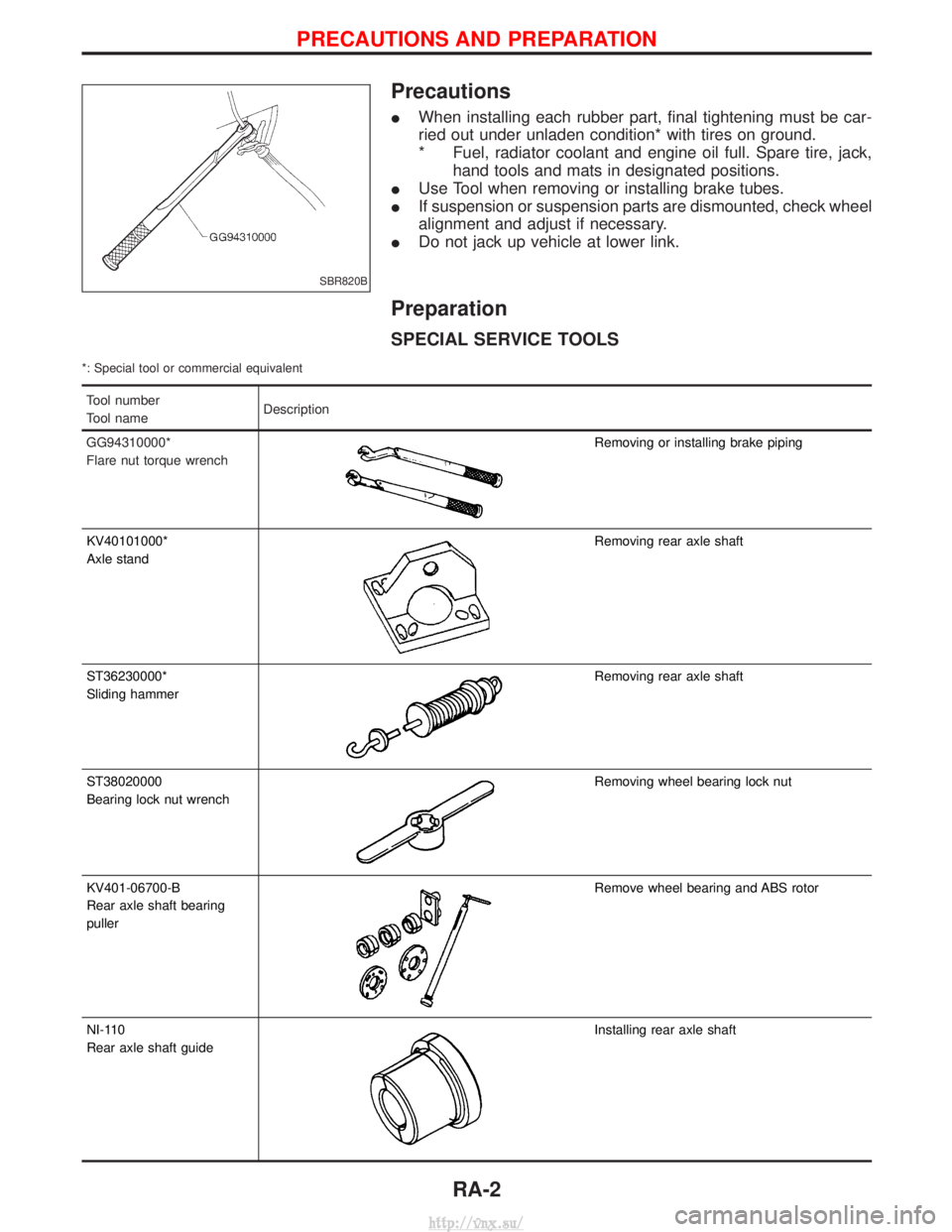
I Use Tool when removing or installing brake tubes.
I If suspension or suspension parts are dismounted, check wheel
alignment and adjust if necessary.
I Do not jack up vehicle at lower link.
Preparation
SPECIAL SERVICE TOOLS
*: Special tool or commercial equivalent
Tool number
Tool name Description
GG94310000*
Flare nut torque wrench
Removing or installing brake piping
KV40101000*
Axle stand
Removing rear axle shaft
ST36230000*
Sliding hammer
Removing rear axle shaft
ST38020000
Bearing lock nut wrench
Removing wheel bearing lock nut
KV401-06700-B
Rear axle shaft bearing
puller
Remove wheel bearing and ABS rotor
NI-110
Rear axle shaft guide
Installing rear axle shaft
SBR820B
PRECAUTIONS AND PREPARATION
RA-2
http://vnx.su/
Page 1168 of 1833
BRAKE SYSTEM
SECTION
BR
CONTENTS
PRECAUTIONS AND PREPARATION ............................3
Supplement Restraint System (SRS) ²AIR BAG²
and ²SEAT BELT PRE-TENSIONER² .........................3
Precautions ..................................................................3
Preparation ..................................................................4
CHECK AND ADJUSTMENT ..........................................5
Checking Brake Fluid Level.........................................5
Checking Brake Line ...................................................5
Changing Brake Fluid ..................................................5
Brake Burnishing Procedure........................................5
BRAKE HYDRAULIC LINE .............................................6
Bleeding Brake System ...............................................8
Removal .......................................................................9
Inspection.....................................................................9
Installation ....................................................................9
LOAD SENSING VALVE ...............................................10
Removal and Installation ...........................................10
Removal ..................................................................... 11
Installation .................................................................. 11
Inspection and Adjustment ........................................12
BRAKE PEDAL AND BRACKET ..................................14
Removal and Installation ...........................................14
Removal .....................................................................15
Installation ..................................................................15
Inspection...................................................................15
Adjustment .................................................................16
MASTER CYLINDER .....................................................17
Removal .....................................................................17
Installation ..................................................................17
BRAKE BOOSTER ........................................................18
Removal and Installation ...........................................18
Inspection...................................................................18
Installation ..................................................................19
VACUUM HOSE .............................................................20
Removal and Installation ...........................................20
Inspection...................................................................22
VACUUM PUMP (TD27Ti engine model) ....................24
Removal and Installation ...........................................24
Inspection...................................................................24 VACUUM PUMP (ZD30DDTi engine model)
...............26
Removal and Installation ...........................................26
FRONT DISC BRAKE ...................................................27
Pad Replacement ......................................................27
Removal .....................................................................28
Disassembly...............................................................28
Inspection...................................................................28
Assembly ...................................................................29
Inspection...................................................................29
Installation ..................................................................31
REAR DRUM BRAKE ...................................................32
Removal .....................................................................33
Shoe Replacement ....................................................34
Inspection...................................................................34
Installation ..................................................................34
PARKING BRAKE CONTROL ......................................36
Removal and Installation ...........................................36
Inspection...................................................................36
Adjustment .................................................................36
ANTI-LOCK BRAKE SYSTEM ......................................38
Purpose......................................................................38
Operation ...................................................................38
ABS Hydraulic Circuit ................................................38
System Description ....................................................39
Removal and Installation ...........................................43
TROUBLE DIAGNOSES ...............................................48
How to Perform Trouble Diagnoses for Quick
and Accurate Repair ..................................................48
Component Parts and Harness Connector
Location .....................................................................49
Circuit Diagram for Quick Pinpoint Check.................50
Wiring Diagram - ABS - .............................................51
CONSULT-II ...............................................................59
CONSULT-II Inspection Procedure............................60
Preliminary Check......................................................66
Ground Circuit Check ................................................67
Diagnostic Procedure 1 (Not self-diagnostic item) ....68
Diagnostic Procedure 2 (Warning lamp stays on
when ignition switch is turned ON)............................70
http://vnx.su/
Page 1172 of 1833
Checking Brake Fluid Level
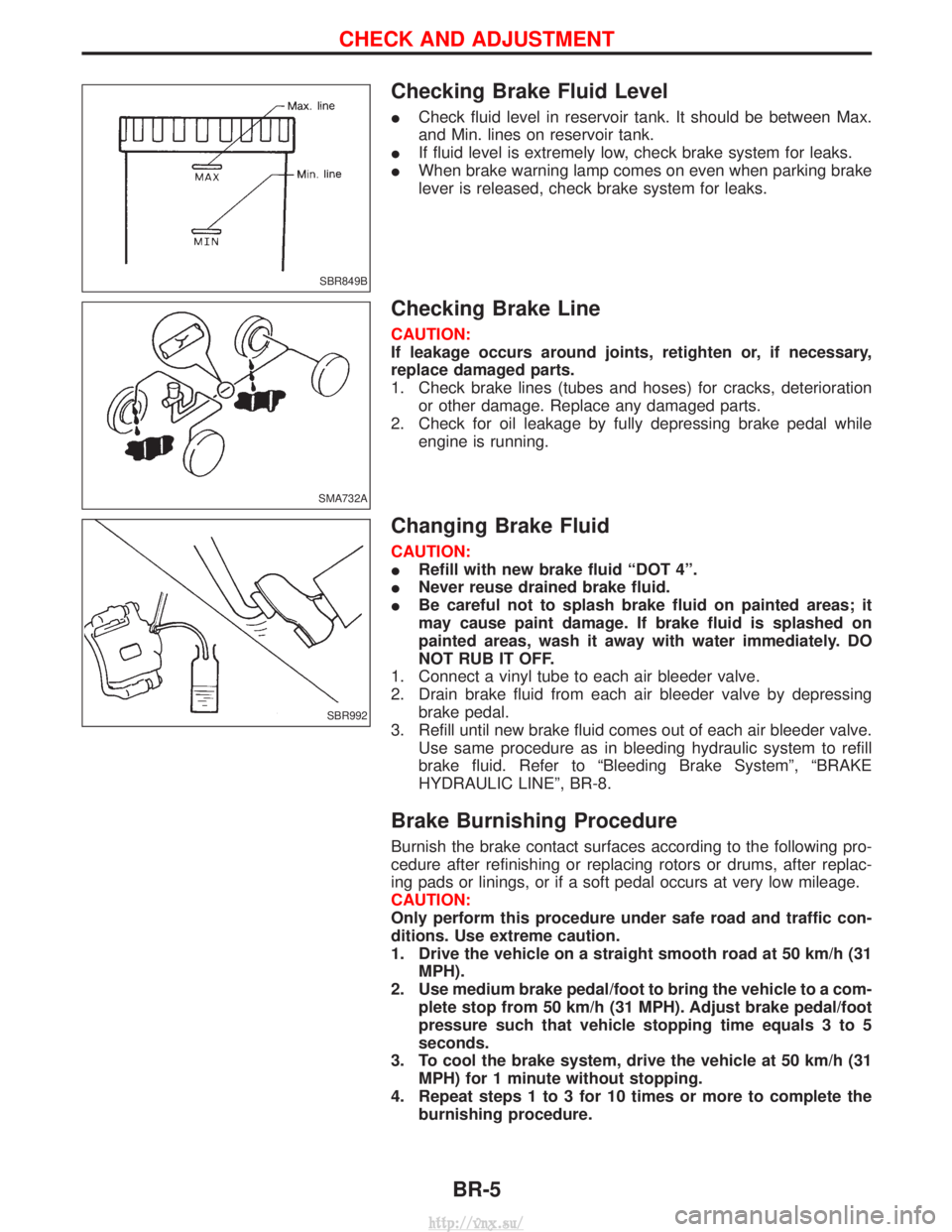
ICheck fluid level in reservoir tank. It should be between Max.
and Min. lines on reservoir tank.
I If fluid level is extremely low, check brake system for leaks.
I When brake warning lamp comes on even when parking brake
lever is released, check brake system for leaks.
Checking Brake Line
CAUTION:
If leakage occurs around joints, retighten or, if necessary,
replace damaged parts.
1. Check brake lines (tubes and hoses) for cracks, deterioration
or other damage. Replace any damaged parts.
2. Check for oil leakage by fully depressing brake pedal while engine is running.
Changing Brake Fluid
CAUTION:
IRefill with new brake fluid ªDOT 4º.
I Never reuse drained brake fluid.
I Be careful not to splash brake fluid on painted areas; it
may cause paint damage. If brake fluid is splashed on
painted areas, wash it away with water immediately. DO
NOT RUB IT OFF.
1. Connect a vinyl tube to each air bleeder valve.
2. Drain brake fluid from each air bleeder valve by depressing brake pedal.
3. Refill until new brake fluid comes out of each air bleeder valve. Use same procedure as in bleeding hydraulic system to refill
brake fluid. Refer to ªBleeding Brake Systemº, ªBRAKE
HYDRAULIC LINEº, BR-8.
Brake Burnishing Procedure
Burnish the brake contact surfaces according to the following pro-
cedure after refinishing or replacing rotors or drums, after replac-
ing pads or linings, or if a soft pedal occurs at very low mileage.
CAUTION:
Only perform this procedure under safe road and traffic con-
ditions. Use extreme caution.
1. Drive the vehicle on a straight smooth road at 50 km/h (31MPH).
2. Use medium brake pedal/foot to bring the vehicle to a com- plete stop from 50 km/h (31 MPH). Adjust brake pedal/foot
pressure such that vehicle stopping time equals 3 to 5
seconds.
3. To cool the brake system, drive the vehicle at 50 km/h (31 MPH) for 1 minute without stopping.
4. Repeat steps 1 to 3 for 10 times or more to complete the burnishing procedure.
SBR849B
SMA732A
SBR992
CHECK AND ADJUSTMENT
BR-5
http://vnx.su/
Page 1180 of 1833
5. Bleed the air from the rear brake piping.
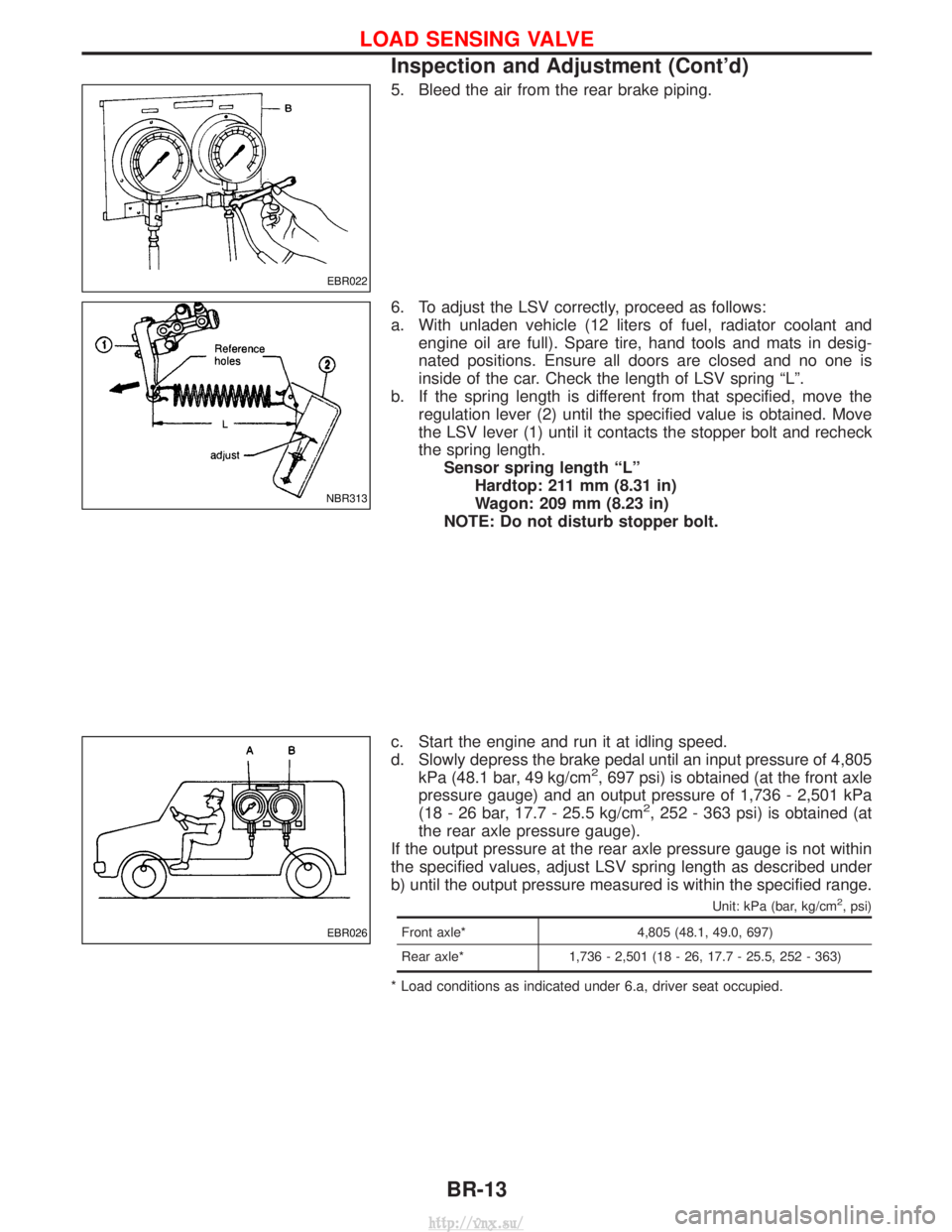
6. To adjust the LSV correctly, proceed as follows:
a. With unladen vehicle (12 liters of fuel, radiator coolant andengine oil are full). Spare tire, hand tools and mats in desig-
nated positions. Ensure all doors are closed and no one is
inside of the car. Check the length of LSV spring ªLº.
b. If the spring length is different from that specified, move the regulation lever (2) until the specified value is obtained. Move
the LSV lever (1) until it contacts the stopper bolt and recheck
the spring length.Sensor spring length ªLº Hardtop: 211 mm (8.31 in)
Wagon: 209 mm (8.23 in)
NOTE: Do not disturb stopper bolt.
c. Start the engine and run it at idling speed.
d. Slowly depress the brake pedal until an input pressure of 4,805 kPa (48.1 bar, 49 kg/cm
2, 697 psi) is obtained (at the front axle
pressure gauge) and an output pressure of 1,736 - 2,501 kPa
(18 - 26 bar, 17.7 - 25.5 kg/cm
2, 252 - 363 psi) is obtained (at
the rear axle pressure gauge).
If the output pressure at the rear axle pressure gauge is not within
the specified values, adjust LSV spring length as described under
b) until the output pressure measured is within the specified range.
Unit: kPa (bar, kg/cm2, psi)
Front axle* 4,805 (48.1, 49.0, 697)
Rear axle* 1,736 - 2,501 (18 - 26, 17.7 - 25.5, 252 - 363)
* Load conditions as indicated under 6.a, driver seat occupied.
EBR022
NBR313
EBR026
LOAD SENSING VALVE
Inspection and Adjustment (Cont'd)
BR-13
http://vnx.su/
Page 1185 of 1833
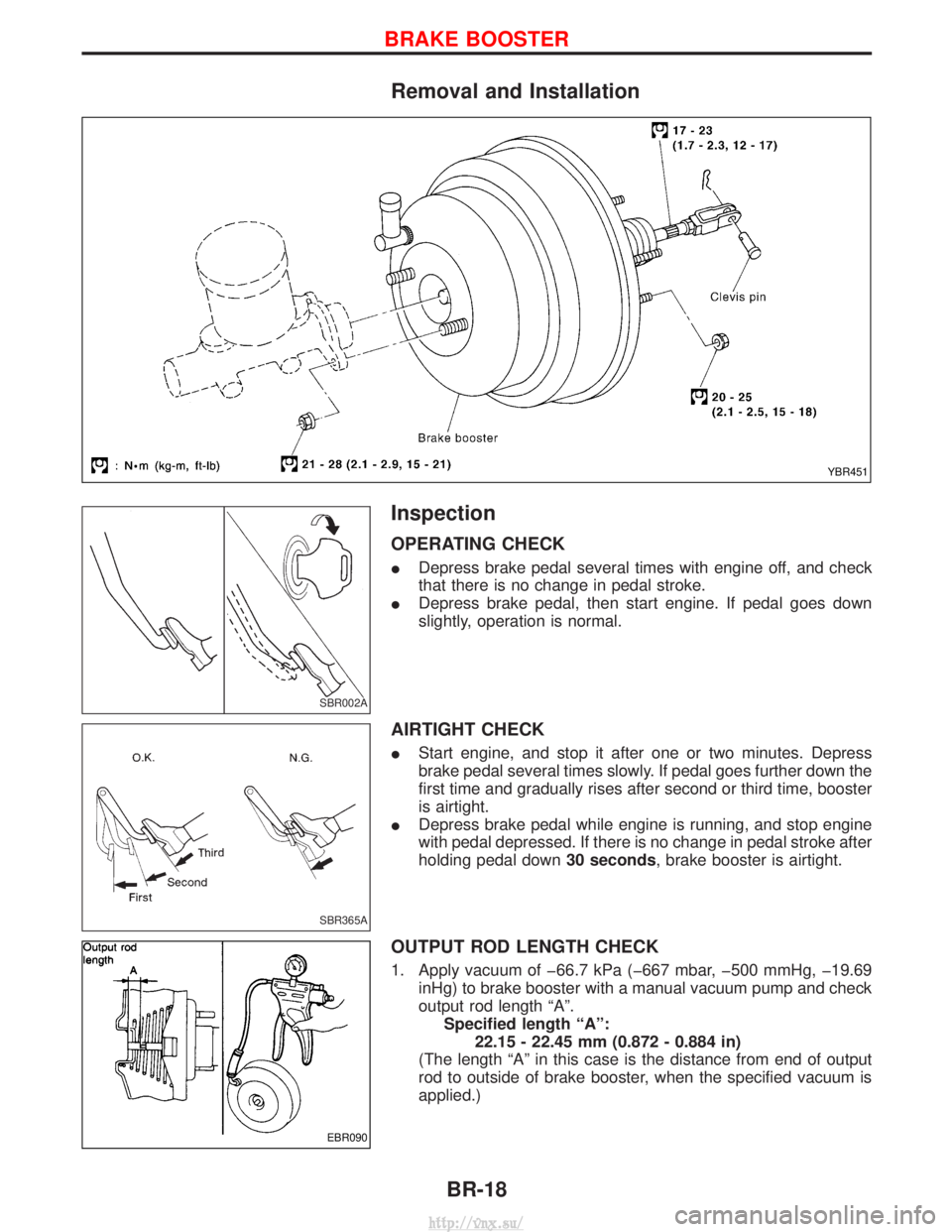
Removal and Installation
Inspection
OPERATING CHECK
IDepress brake pedal several times with engine off, and check
that there is no change in pedal stroke.
I Depress brake pedal, then start engine. If pedal goes down
slightly, operation is normal.
AIRTIGHT CHECK
IStart engine, and stop it after one or two minutes. Depress
brake pedal several times slowly. If pedal goes further down the
first time and gradually rises after second or third time, booster
is airtight.
I Depress brake pedal while engine is running, and stop engine
with pedal depressed. If there is no change in pedal stroke after
holding pedal down 30 seconds, brake booster is airtight.
OUTPUT ROD LENGTH CHECK
1. Apply vacuum of þ66.7 kPa (þ667 mbar, þ500 mmHg, þ19.69
inHg) to brake booster with a manual vacuum pump and check
output rod length ªAº.Specified length ªAº: 22.15 - 22.45 mm (0.872 - 0.884 in)
(The length ªAº in this case is the distance from end of output
rod to outside of brake booster, when the specified vacuum is
applied.)
YBR451
SBR002A
SBR365A
EBR090
BRAKE BOOSTER
BR-18
http://vnx.su/
Page 1189 of 1833
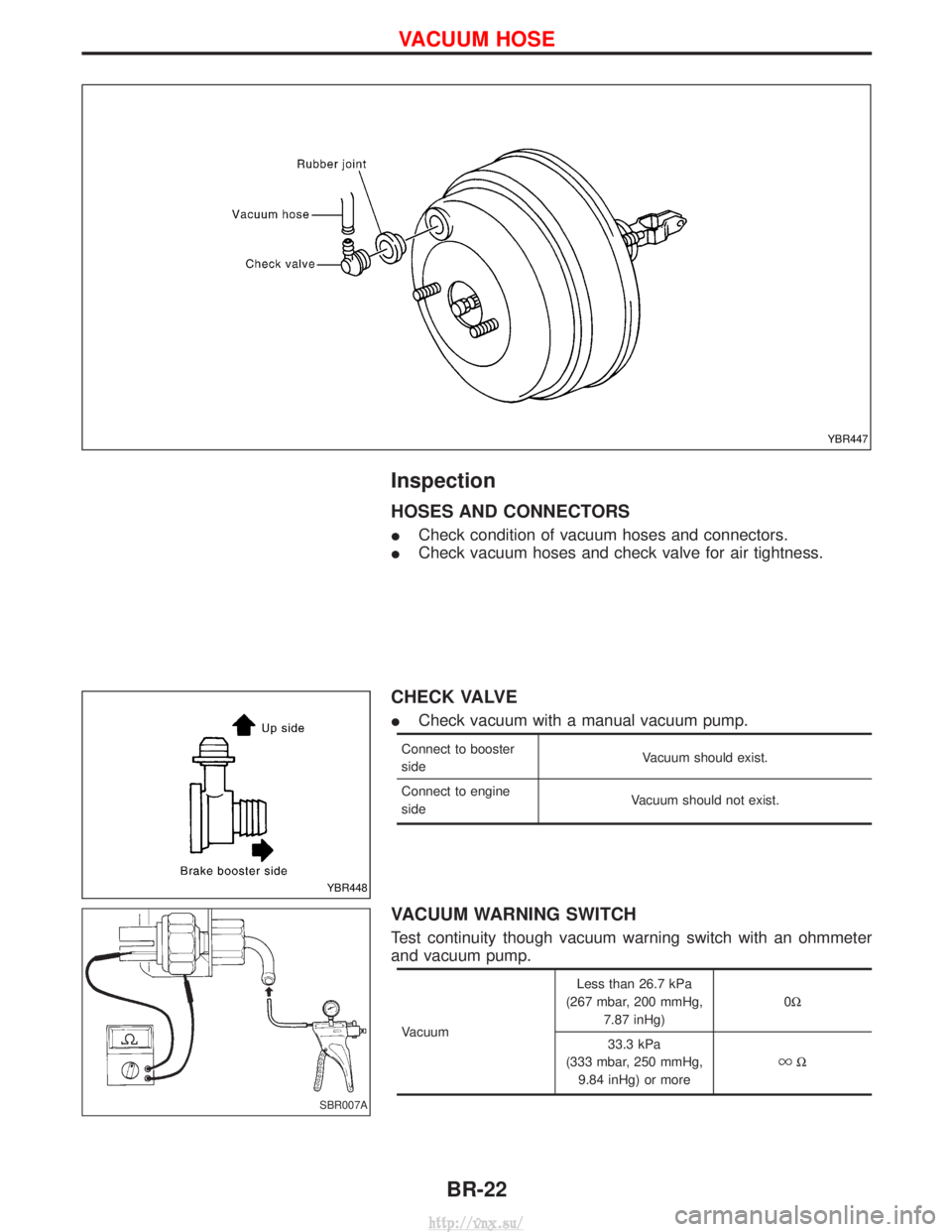
Inspection
HOSES AND CONNECTORS
ICheck condition of vacuum hoses and connectors.
I Check vacuum hoses and check valve for air tightness.
CHECK VALVE
ICheck vacuum with a manual vacuum pump.
Connect to booster
side Vacuum should exist.
Connect to engine
side Vacuum should not exist.
VACUUM WARNING SWITCH
Test continuity though vacuum warning switch with an ohmmeter
and vacuum pump.
VacuumLess than 26.7 kPa
(267 mbar, 200 mmHg, 7.87 inHg) 0W
33.3 kPa
(333 mbar, 250 mmHg, 9.84 inHg) or more
W
YBR447
YBR448
SBR007A
VACUUM HOSE
BR-22
http://vnx.su/
Page 1190 of 1833
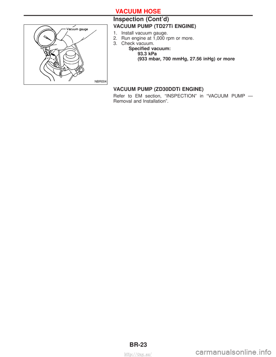
VACUUM PUMP (TD27Ti ENGINE)
1. Install vacuum gauge.
2. Run engine at 1,000 rpm or more.
3. Check vacuum.Specified vacuum:93.3 kPa
(933 mbar, 700 mmHg, 27.56 inHg) or more
VACUUM PUMP (ZD30DDTi ENGINE)
Refer to EM section, ªINSPECTIONº in ªVACUUM PUMP Ð
Removal and Installationº.
NBR004
VACUUM HOSE
Inspection (Cont'd)
BR-23
http://vnx.su/
Page 1191 of 1833
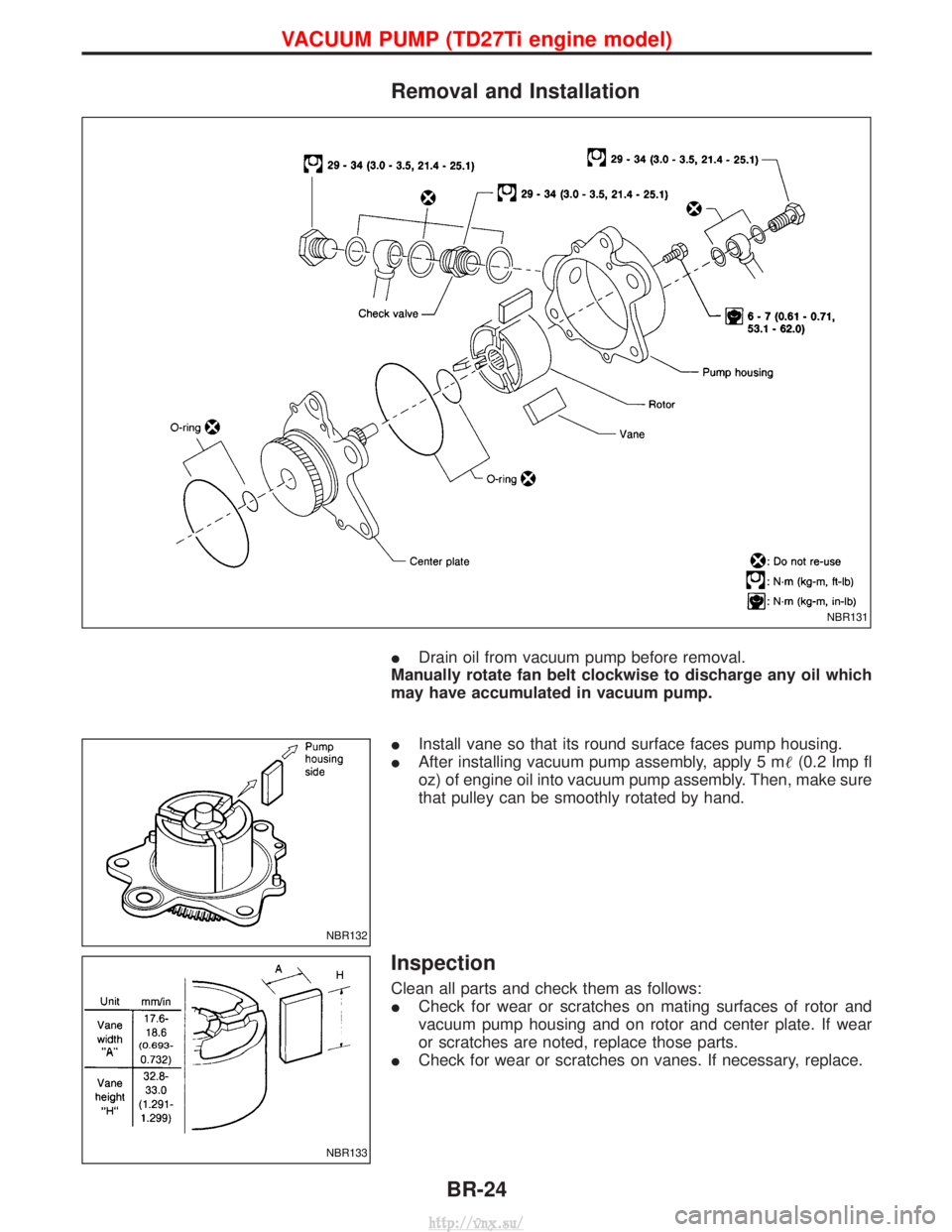
Removal and Installation
IDrain oil from vacuum pump before removal.
Manually rotate fan belt clockwise to discharge any oil which
may have accumulated in vacuum pump.
I Install vane so that its round surface faces pump housing.
I After installing vacuum pump assembly, apply 5 m (0.2 Imp fl
oz) of engine oil into vacuum pump assembly. Then, make sure
that pulley can be smoothly rotated by hand.
Inspection
Clean all parts and check them as follows:
I Check for wear or scratches on mating surfaces of rotor and
vacuum pump housing and on rotor and center plate. If wear
or scratches are noted, replace those parts.
I Check for wear or scratches on vanes. If necessary, replace.
NBR131
NBR132
NBR133
VACUUM PUMP (TD27Ti engine model)
BR-24
http://vnx.su/