2004 NISSAN TERRANO power steering
[x] Cancel search: power steeringPage 85 of 1833
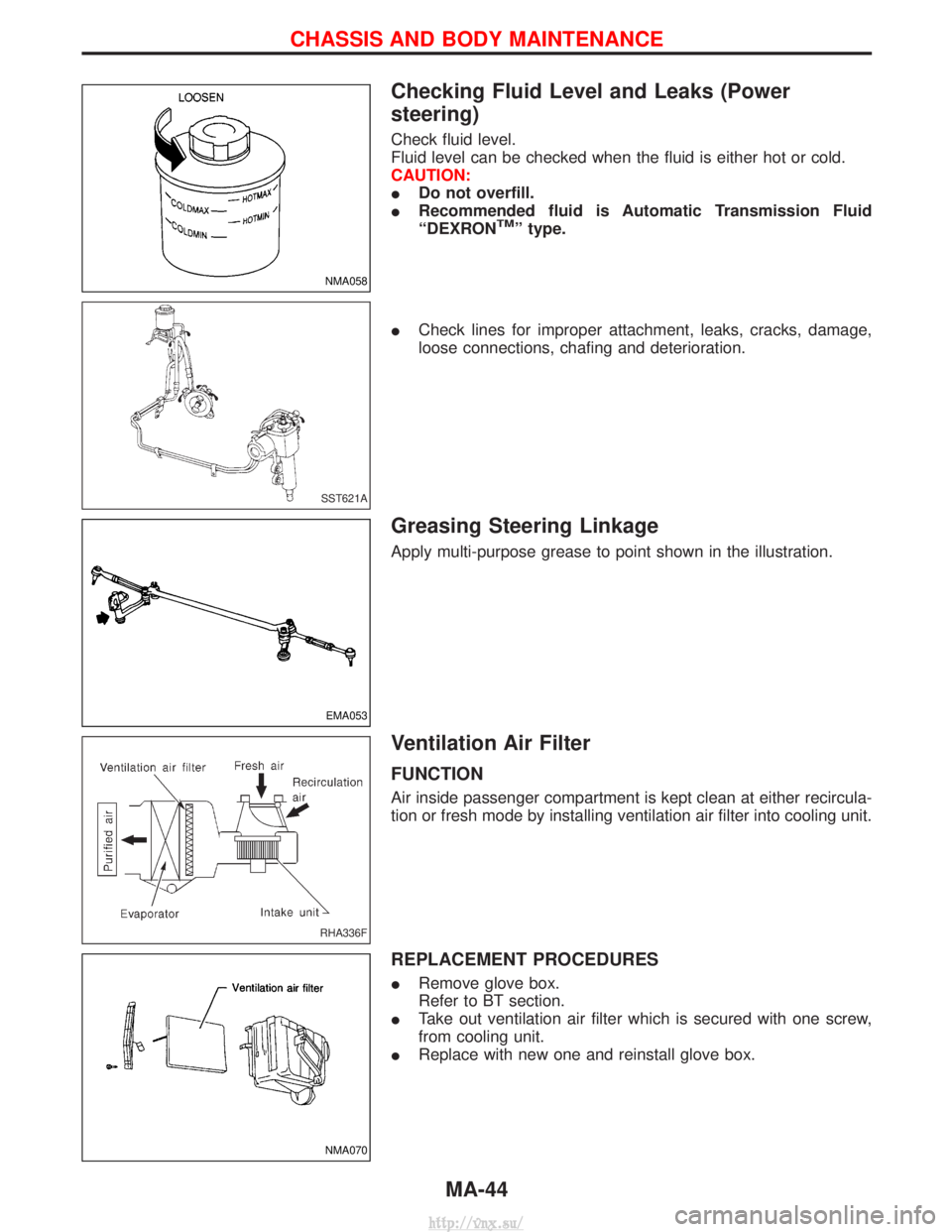
Checking Fluid Level and Leaks (Power
steering)
Check fluid level.
Fluid level can be checked when the fluid is either hot or cold.
CAUTION:
IDo not overfill.
I Recommended fluid is Automatic Transmission Fluid
ªDEXRON
TMº type.
I Check lines for improper attachment, leaks, cracks, damage,
loose connections, chafing and deterioration.
Greasing Steering Linkage
Apply multi-purpose grease to point shown in the illustration.
Ventilation Air Filter
FUNCTION
Air inside passenger compartment is kept clean at either recircula-
tion or fresh mode by installing ventilation air filter into cooling unit.
REPLACEMENT PROCEDURES
IRemove glove box.
Refer to BT section.
I Take out ventilation air filter which is secured with one screw,
from cooling unit.
I Replace with new one and reinstall glove box.
NMA058
SST621A
EMA053
RHA336F
NMA070
CHASSIS AND BODY MAINTENANCE
MA-44
http://vnx.su/
Page 89 of 1833
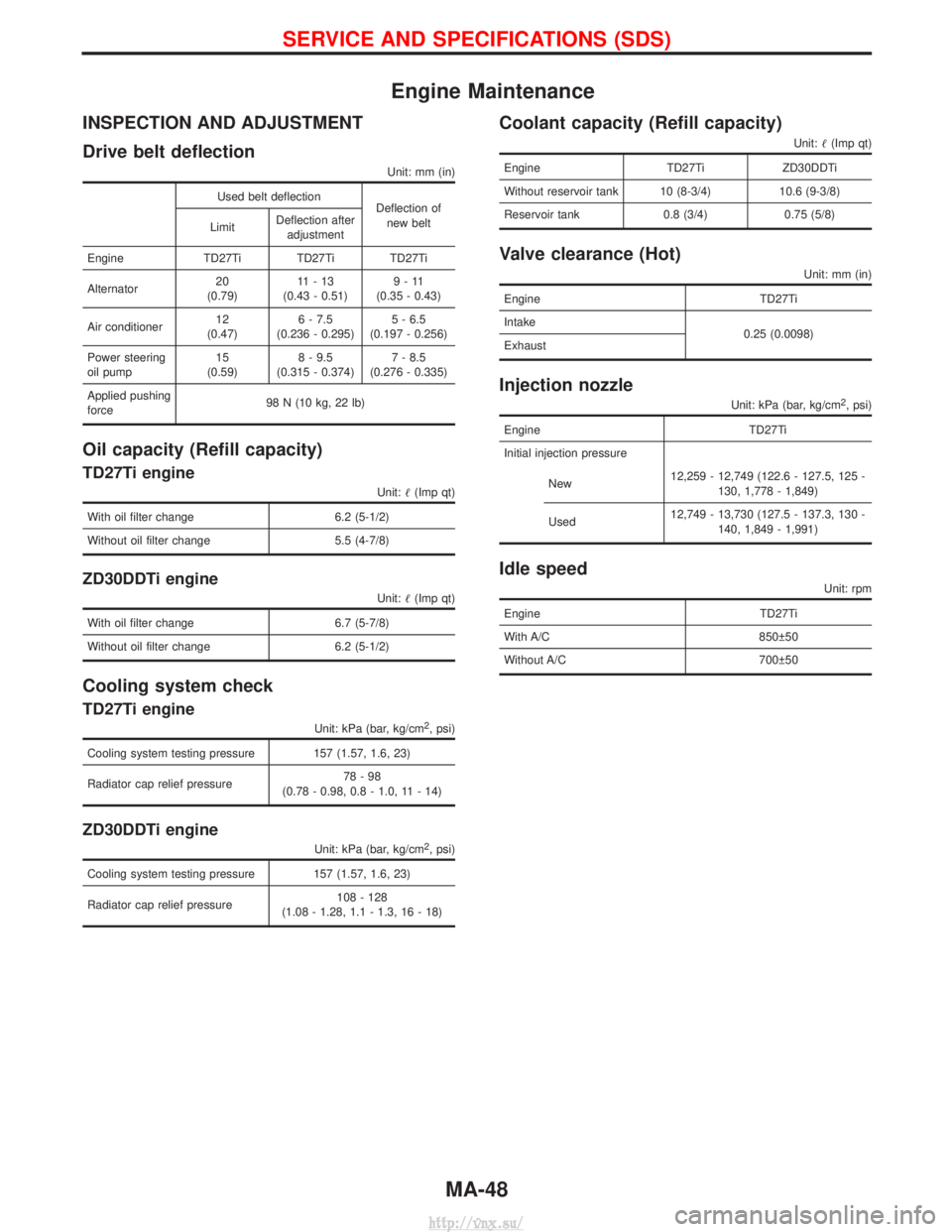
Engine Maintenance
INSPECTION AND ADJUSTMENT
Drive belt deflection
Unit: mm (in)
Used belt deflectionDeflection of
new belt
Limit Deflection after
adjustment
Engine TD27Ti TD27Ti TD27Ti
Alternator 20
(0.79) 11-13
(0.43 - 0.51) 9-11
(0.35 - 0.43)
Air conditioner 12
(0.47) 6 - 7.5
(0.236 - 0.295) 5 - 6.5
(0.197 - 0.256)
Power steering
oil pump 15
(0.59) 8 - 9.5
(0.315 - 0.374) 7 - 8.5
(0.276 - 0.335)
Applied pushing
force 98 N (10 kg, 22 lb)
Oil capacity (Refill capacity)
TD27Ti engine
Unit:
(Imp qt)
With oil filter change 6.2 (5-1/2)
Without oil filter change 5.5 (4-7/8)
ZD30DDTi engine
Unit: (Imp qt)
With oil filter change 6.7 (5-7/8)
Without oil filter change 6.2 (5-1/2)
Cooling system check
TD27Ti engine
Unit: kPa (bar, kg/cm2, psi)
Cooling system testing pressure 157 (1.57, 1.6, 23)
Radiator cap relief pressure 78-98
(0.78 - 0.98, 0.8 - 1.0, 11 - 14)
ZD30DDTi engine
Unit: kPa (bar, kg/cm2, psi)
Cooling system testing pressure 157 (1.57, 1.6, 23)
Radiator cap relief pressure 108 - 128
(1.08 - 1.28, 1.1 - 1.3, 16 - 18)
Coolant capacity (Refill capacity)
Unit: (Imp qt)
Engine TD27TiZD30DDTi
Without reservoir tank 10 (8-3/4) 10.6 (9-3/8)
Reservoir tank 0.8 (3/4) 0.75 (5/8)
Valve clearance (Hot)
Unit: mm (in)
Engine TD27Ti
Intake 0.25 (0.0098)
Exhaust
Injection nozzle
Unit: kPa (bar, kg/cm2, psi)
Engine TD27Ti
Initial injection pressure
New 12,259 - 12,749 (122.6 - 127.5, 125 -
130, 1,778 - 1,849)
Used 12,749 - 13,730 (127.5 - 137.3, 130 -
140, 1,849 - 1,991)
Idle speed
Unit: rpm
Engine TD27Ti
With A/C 850 50
Without A/C 700 50
SERVICE AND SPECIFICATIONS (SDS)
MA-48
http://vnx.su/
Page 118 of 1833
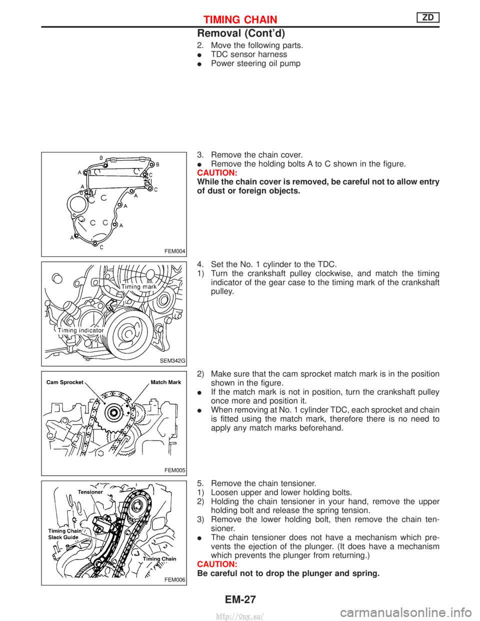
2. Move the following parts.
ITDC sensor harness
I Power steering oil pump
3. Remove the chain cover.
I Remove the holding bolts A to C shown in the figure.
CAUTION:
While the chain cover is removed, be careful not to allow entry
of dust or foreign objects.
4. Set the No. 1 cylinder to the TDC.
1) Turn the crankshaft pulley clockwise, and match the timing indicator of the gear case to the timing mark of the crankshaft
pulley.
2) Make sure that the cam sprocket match mark is in the position shown in the figure.
I If the match mark is not in position, turn the crankshaft pulley
once more and position it.
I When removing at No. 1 cylinder TDC, each sprocket and chain
is fitted using the match mark, therefore there is no need to
apply any match marks beforehand.
5. Remove the chain tensioner.
1) Loosen upper and lower holding bolts.
2) Holding the chain tensioner in your hand, remove the upper holding bolt and release the spring tension.
3) Remove the lower holding bolt, then remove the chain ten- sioner.
I The chain tensioner does not have a mechanism which pre-
vents the ejection of the plunger. (It does have a mechanism
which prevents the plunger from returning.)
CAUTION:
Be careful not to drop the plunger and spring.
FEM004
SEM342G
FEM005
FEM006
TIMING CHAINZD
Removal (Cont'd)
EM-27
http://vnx.su/
Page 155 of 1833

Engine room (Left)
3. Remove air duct and air cleaner case.
4. Disconnect vacuum hose to the vehicle on the engine.
5. Disconnect harness connectors from alternator and air com-pressor.
6. Remove alternator.
7. After removing refrigerant, remove pipes of air compressor and inlet/outlet.
8. Disconnect heating hose, install blank cap to hose to prevent coolant from leaking.
9. Remove heating pipe.
10. Remove heat insulator.
11. Remove catalytic converter.
Engine room (Right)
12. Remove power steering reservoir tank from bracket, and fix it to the vehicle with a rope.
CAUTION:
Keep the reservoir tank level when fixing to prevent oil leak.
13. Remove fuel feed and return hoses.
CAUTION:
Install blank caps immediately to avoid fuel leakage.
14. Remove all harness connectors on the engine, and move har- nesses to the side of the vehicle.
Vehicle underfloor
15. Remove starter motor.
16. Detach A/T oil cooler pipes from oil pan. (A/T model)
17. Remove rear propeller shaft.
18. Remove mounting bolts to secure the engine to transmission.
1) Remove torque converter installation bolt. (A/T model)
2) Lift transmission bottom with transmission jack, and removerear mount members from the vehicle.
3) Lower transmission with the jack, and remove upper mounting bolts securing the engine to transmission.
4) Lift transmission with the jack, and reinstall rear mount mem- bers to the vehicle.
5) Position the jack to the front side of transmission.
6) Remove remaining mounting bolts securing the engine to trans- mission.
Removal operation
19. Remove air conditioner high pressure pipes at the rear of theengine room.
I This is due to some inconvenience in the rear slinger installa-
tion.
20. Install the engine slingers (standard service part) to front-left and rear-right.
:25-28N ×m (2.5 - 2.9 kg-m, 18 - 20 ft-lb)
WARNING:
For engines without engine slingers, attach proper slingers
and bolts described in the PARTS CATALOG.
FEM082
ENGINE REMOVALZD
Removal (Cont'd)
EM-64
http://vnx.su/
Page 303 of 1833
REMOVAL
1. Remove the following:
IEngine coolant draining
I Charge air cooler
I Air inlet pipe
I Throttle body
I Rocker cover
I Oil level gauge guide
I EGR cooler
I EGR guide tube
I EGR volume control solenoid valve
I Fuel hose
I Injection tube
I Radiator upper hose
I Radiator shroud
I Cooling fan
I Drive belt
I Vacuum pipe
I Vacuum pump
2. Move the power steering pump.
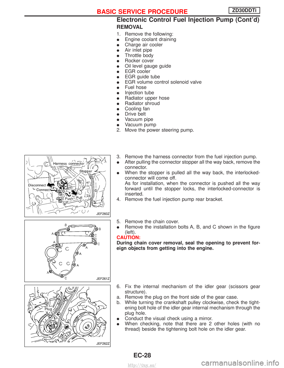
3. Remove the harness connector from the fuel injection pump.
I After pulling the connector stopper all the way back, remove the
connector.
I When the stopper is pulled all the way back, the interlocked-
connector will come off.
As for installation, when the connector is pushed all the way
forward until the stopper locks, the interlocked-connector is
inserted.
4. Remove the fuel injection pump rear bracket.
5. Remove the chain cover.
I Remove the installation bolts A, B, and C shown in the figure
(left).
CAUTION:
During chain cover removal, seal the opening to prevent for-
eign objects from getting into the engine.
6. Fix the internal mechanism of the idler gear (scissors gear structure).
a. Remove the plug on the front side of the gear case.
b. While turning the crankshaft pulley clockwise, check the tight- ening bolt hole of the idler gear internal mechanism through the
plug hole.
I Conduct the visual check using a mirror.
I When checking, note that there are 2 other holes (with no
thread) beside the tightening bolt hole on the idler gear.
JEF260Z
JEF261Z
JEF262Z
BASIC SERVICE PROCEDUREZD30DDTi
Electronic Control Fuel Injection Pump (Cont'd)
EC-28
http://vnx.su/
Page 1254 of 1833
STEERING SYSTEM
SECTION
ST
CONTENTS
PRECAUTIONS ...............................................................2
Supplemental Restraint System (SRS) ²AIR
BAG² and²SEAT BELT PRE-TENSIONER² ...............2
Precautions for SRS ²AIR BAG² and²SEAT
BELT PRE-TENSIONER² Service ...............................2
Precautions for Steering System .................................2
PREPARATION ................................................................3
Special Service Tools ..................................................3
ON-VEHICLE SERVICE ..................................................4
Checking Steering Wheel Play ....................................4
Checking Neutral Position on Steering Wheel ............4
Front Wheel Turning Angle ..........................................4
Checking and Adjusting Drive Belts ............................4
Checking Fluid Level ...................................................4
Checking Fluid Leakage ..............................................5
Bleeding Hydraulic System..........................................5
Checking Steering Wheel Turning Force ....................6
Checking Hydraulic System.........................................7 STEERING WHEEL AND STEERING COLUMN
............8
Removal and Installation .............................................8
Disassembly and Assembly .......................................10
Inspection................................................................... 11
POWER STEERING GEAR ...........................................12
Description .................................................................12
Removal and Installation ...........................................14
Inspection and Adjustment ........................................15
POWER STEERING OIL PUMP ....................................16
Removal and Installation ...........................................16
STEERING LINKAGE ....................................................17
Removal and Installation ...........................................17
Disassembly and Assembly .......................................19
Inspection...................................................................20
SERVICE DATA AND SPECIFICATIONS (SDS) ..........22
General Specifications ...............................................22
Inspection and Adjustment ........................................22
http://vnx.su/
Page 1257 of 1833
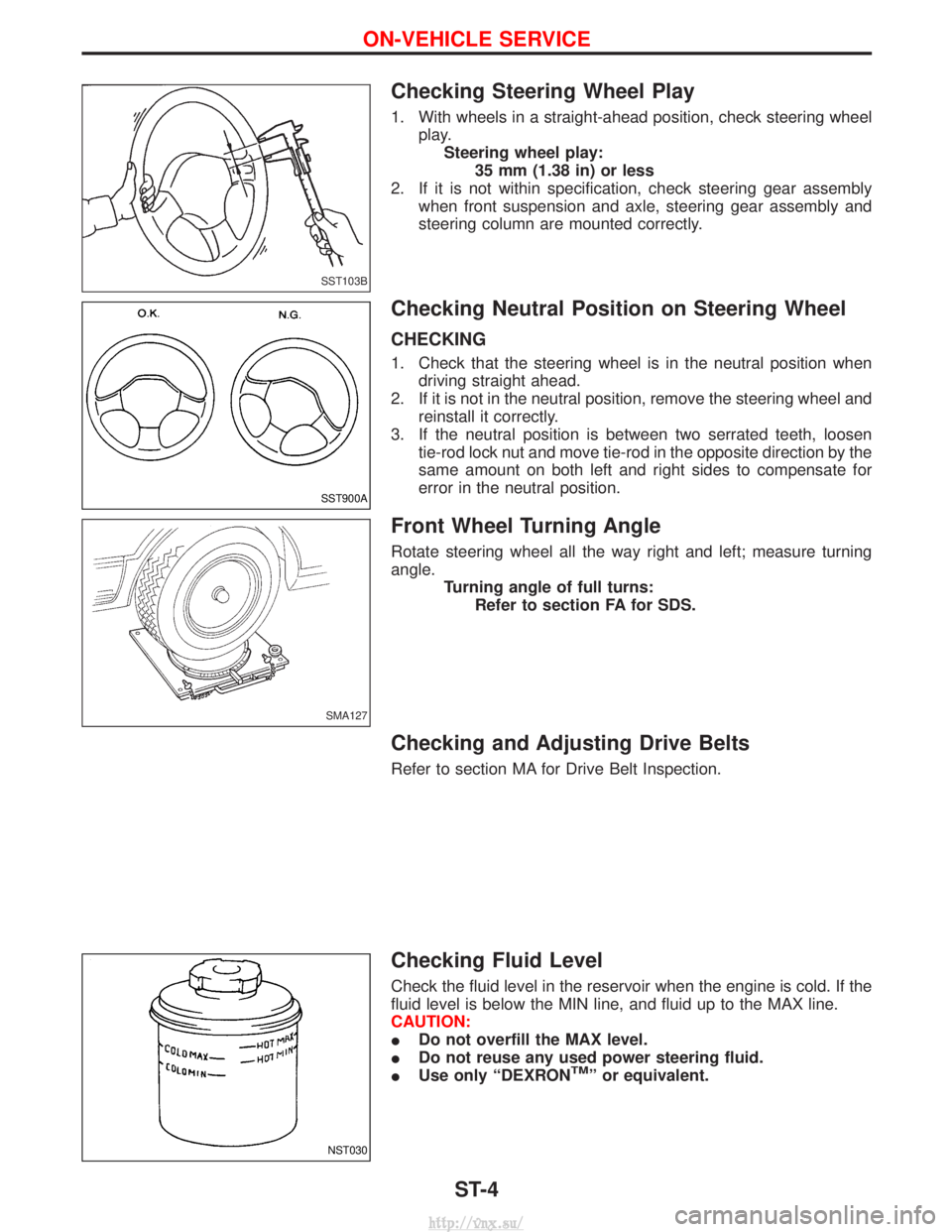
Checking Steering Wheel Play
1. With wheels in a straight-ahead position, check steering wheelplay.Steering wheel play: 35 mm (1.38 in) or less
2. If it is not within specification, check steering gear assembly when front suspension and axle, steering gear assembly and
steering column are mounted correctly.
Checking Neutral Position on Steering Wheel
CHECKING
1. Check that the steering wheel is in the neutral position whendriving straight ahead.
2. If it is not in the neutral position, remove the steering wheel and reinstall it correctly.
3. If the neutral position is between two serrated teeth, loosen tie-rod lock nut and move tie-rod in the opposite direction by the
same amount on both left and right sides to compensate for
error in the neutral position.
Front Wheel Turning Angle
Rotate steering wheel all the way right and left; measure turning
angle. Turning angle of full turns:Refer to section FA for SDS.
Checking and Adjusting Drive Belts
Refer to section MA for Drive Belt Inspection.
Checking Fluid Level
Check the fluid level in the reservoir when the engine is cold. If the
fluid level is below the MIN line, and fluid up to the MAX line.
CAUTION:
IDo not overfill the MAX level.
I Do not reuse any used power steering fluid.
I Use only ªDEXRON
TMº or equivalent.
SST103B
SST900A
SMA127
NST030
ON-VEHICLE SERVICE
ST-4
http://vnx.su/
Page 1259 of 1833
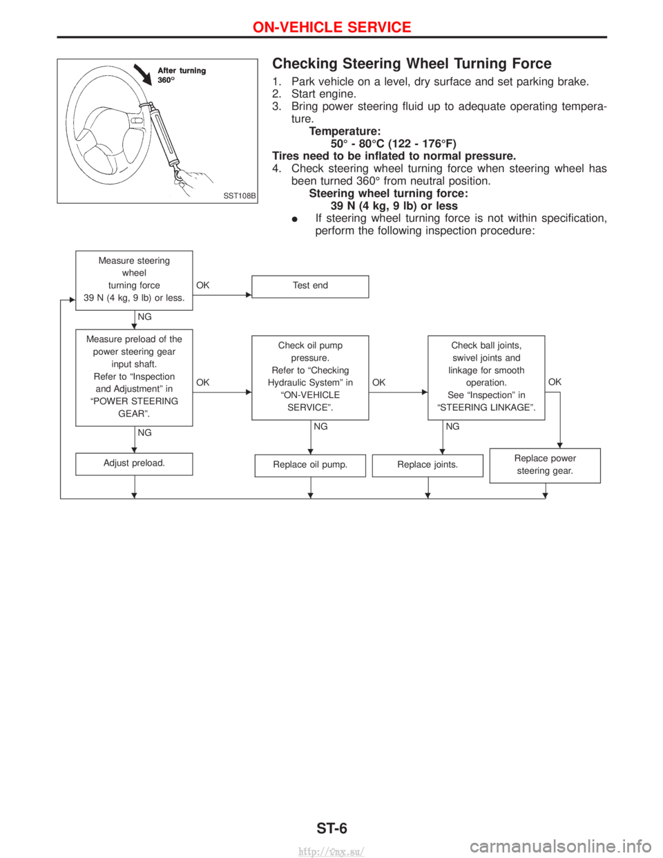
Checking Steering Wheel Turning Force
1. Park vehicle on a level, dry surface and set parking brake.
2. Start engine.
3. Bring power steering fluid up to adequate operating tempera-ture.Temperature: 50É - 80ÉC (122 - 176ÉF)
Tires need to be inflated to normal pressure.
4. Check steering wheel turning force when steering wheel has been turned 360É from neutral position.Steering wheel turning force: 39 N (4 kg, 9 lb) or less
I If steering wheel turning force is not within specification,
perform the following inspection procedure:
E
Measure steering
wheel
turning force
39 N (4 kg, 9 lb) or less.
NG
EOK Test end
Measure preload of the
power steering gear input shaft.
Refer to ªInspection and Adjustmentº in
ªPOWER STEERING GEARº.
NG
EOK Check oil pump
pressure.
Refer to ªChecking
Hydraulic Systemº in ªON-VEHICLESERVICEº.
NG
EOK Check ball joints,
swivel joints and
linkage for smooth operation.
See ªInspectionº in
ªSTEERING LINKAGEº.
NG OK
Adjust preload.Replace oil pump.Replace joints.Replace power
steering gear.
SST108B
H
HHHH
HHHH
ON-VEHICLE SERVICE
ST-6
http://vnx.su/