2004 NISSAN TERRANO power steering
[x] Cancel search: power steeringPage 1265 of 1833
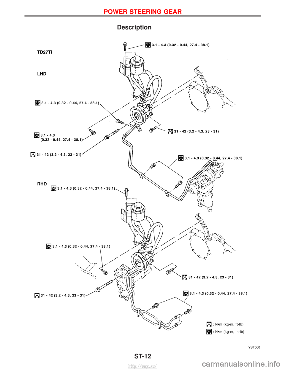
Description
YST060
POWER STEERING GEAR
ST-12
http://vnx.su/
Page 1266 of 1833
YST061
POWER STEERING GEAR
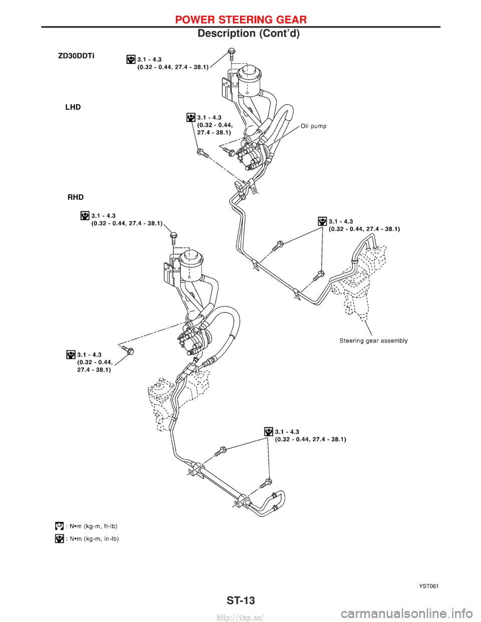
Description (Cont'd)ST-13
http://vnx.su/
Page 1267 of 1833
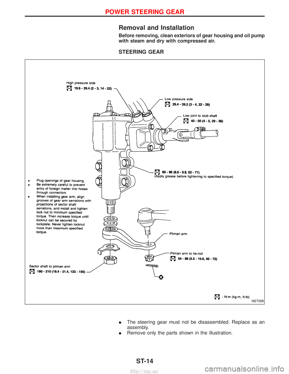
Removal and Installation
Before removing, clean exteriors of gear housing and oil pump
with steam and dry with compressed air.
STEERING GEAR
IThe steering gear must not be disassembled. Replace as an
assembly.
I Remove only the parts shown in the illustration.
NST008
POWER STEERING GEAR
ST-14
http://vnx.su/
Page 1268 of 1833
Inspection and Adjustment
STEERING GEAR PRELOAD
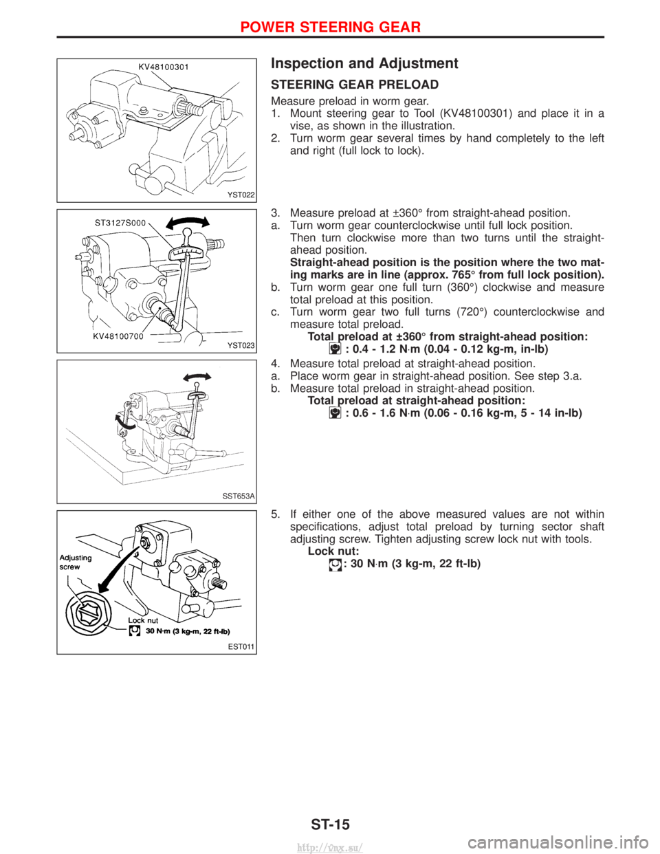
Measure preload in worm gear.
1. Mount steering gear to Tool (KV48100301) and place it in avise, as shown in the illustration.
2. Turn worm gear several times by hand completely to the left and right (full lock to lock).
3. Measure preload at 360É from straight-ahead position.
a. Turn worm gear counterclockwise until full lock position. Then turn clockwise more than two turns until the straight-
ahead position.
Straight-ahead position is the position where the two mat-
ing marks are in line (approx. 765É from full lock position).
b. Turn worm gear one full turn (360É) clockwise and measure total preload at this position.
c. Turn worm gear two full turns (720É) counterclockwise and measure total preload.Total preload at 360É from straight-ahead position:
: 0.4 - 1.2 N ×m (0.04 - 0.12 kg-m, in-lb)
4. Measure total preload at straight-ahead position.
a. Place worm gear in straight-ahead position. See step 3.a.
b. Measure total preload in straight-ahead position. Total preload at straight-ahead position:
: 0.6 - 1.6 N ×m (0.06 - 0.16 kg-m ,5-14in-lb)
5. If either one of the above measured values are not within specifications, adjust total preload by turning sector shaft
adjusting screw. Tighten adjusting screw lock nut with tools.Lock nut:
:30N ×m (3 kg-m, 22 ft-lb)
YST022
YST023
SST653A
EST011
POWER STEERING GEAR
ST-15
http://vnx.su/
Page 1269 of 1833
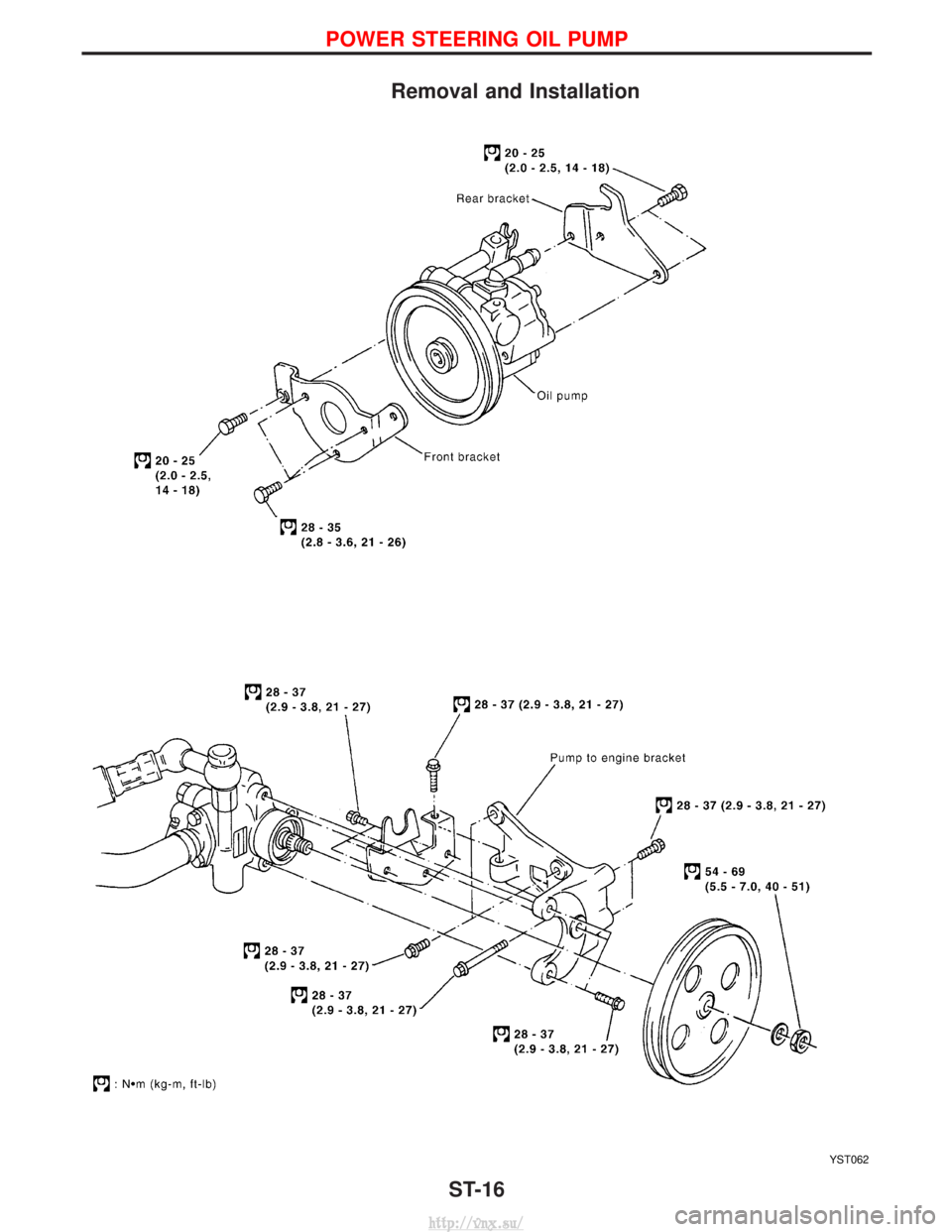
Removal and Installation
YST062
POWER STEERING OIL PUMP
ST-16
http://vnx.su/
Page 1283 of 1833
Precautions
SUPPLEMENTAL RESTRAINT SYSTEM (SRS) ªAIR BAGº AND ªSEAT BELT
PRE-TENSIONERº
The Supplemental Restraint System such as ªAIR BAGº and ªSEAT BELT PRE-TENSIONERº used along with
a seat belt, helps to reduce the risk or severity of injury to the driver and front passenger for certain types of
collision. The SRS composition which is available to NISSAN MODEL R20 is as follows (The composition
varies according to the destination and optional equipment.):
IFor a frontal collision
The Supplemental Restraint System consists of driver air bag module (located in the center of the steer-
ing wheel), front passenger air bag module (located on the instrument panel on passenger side), front seat
belt pre-tensioners, a diagnosis sensor unit, warning lamp, wiring harness and spiral cable.
I For a side collision
The Supplemental Restraint System consists of front side air bag module (located in the outer side of front
seat), side air bag (satellite) sensor, diagnosis sensor unit (one of components of air bags for a frontal
collision), wiring harness, warning lamp (one of components of air bags for a frontal collision).
WARNING:
I To avoid rendering the SRS inoperative, which could increase the risk of personal injury or death
in the event of a collision which would result in air bag inflation, all maintenance should be per-
formed by an authorized NISSAN dealer.
I Improper maintenance, including incorrect removal and installation of the SRS, can lead to per-
sonal injury caused by unintentional activation of the system.
I Do not use electrical test equipment on any circuit related to the SRS unless instructed to in this
Service Manual. Spiral cable and wiring harnesses covered with yellow insulation tape either just
before the harness connectors or for the complete harness are related to the SRS.
PRECAUTIONS FOR SRS ªAIR BAGº AND ªSEAT BELT PRE-TENSIONERº SERVICE
IDo not use electrical test equipment to check SRS circuits unless instructed to in this Service Manual.
I Before servicing the SRS, turn ignition switch ªOFFº, disconnect both battery cables and wait at least 3
minutes.
For approximately 3 minutes after the cables are removed, it is still possible for the air bag and seat belt
pre-tensioner to deploy. Therefore, do not work on any SRS connectors or wires until at least 3 minutes
have passed.
I Diagnosis sensor unit must always be installed with their arrow marks ª +º pointing towards the front of
the vehicle for proper operation. Also check diagnosis sensor unit for cracks, deformities or rust before
installation and replace as required.
I The spiral cable must be aligned with the neutral position since its rotations are limited. Do not attempt to
turn steering wheel or column after removal of steering gear.
I Handle air bag module carefully. Always place driver and front passenger air bag modules with the pad
side facing upward and place front side air bag module (built-in type) standing with stud bolt side setting
bottom.
I Conduct self-diagnosis to check entire SRS for proper function after replacing any components.
I After air bag inflates, the front instrument panel assembly should be replaced if damaged.
WIRING DIAGRAMS AND TROUBLE DIAGNOSIS
When you read wiring diagrams, refer to the following:
IGI-10, ªHOW TO READ WIRING DIAGRAMSº
I EL-8, ªPOWER SUPPLY ROUTINGº for power distribution circuit
When you perform trouble diagnosis, refer to the following:
I GI-25, ªHOW TO FOLLOW TEST GROUPS IN TROUBLE DIAGNOSISº
I GI-22, ªHOW TO PERFORM EFFICIENT DIAGNOSES FOR AN ELECTRICAL INCIDENTº
SUPPLEMENTAL RESTRAINT SYSTEM (SRS)
RS-8
http://vnx.su/
Page 1494 of 1833
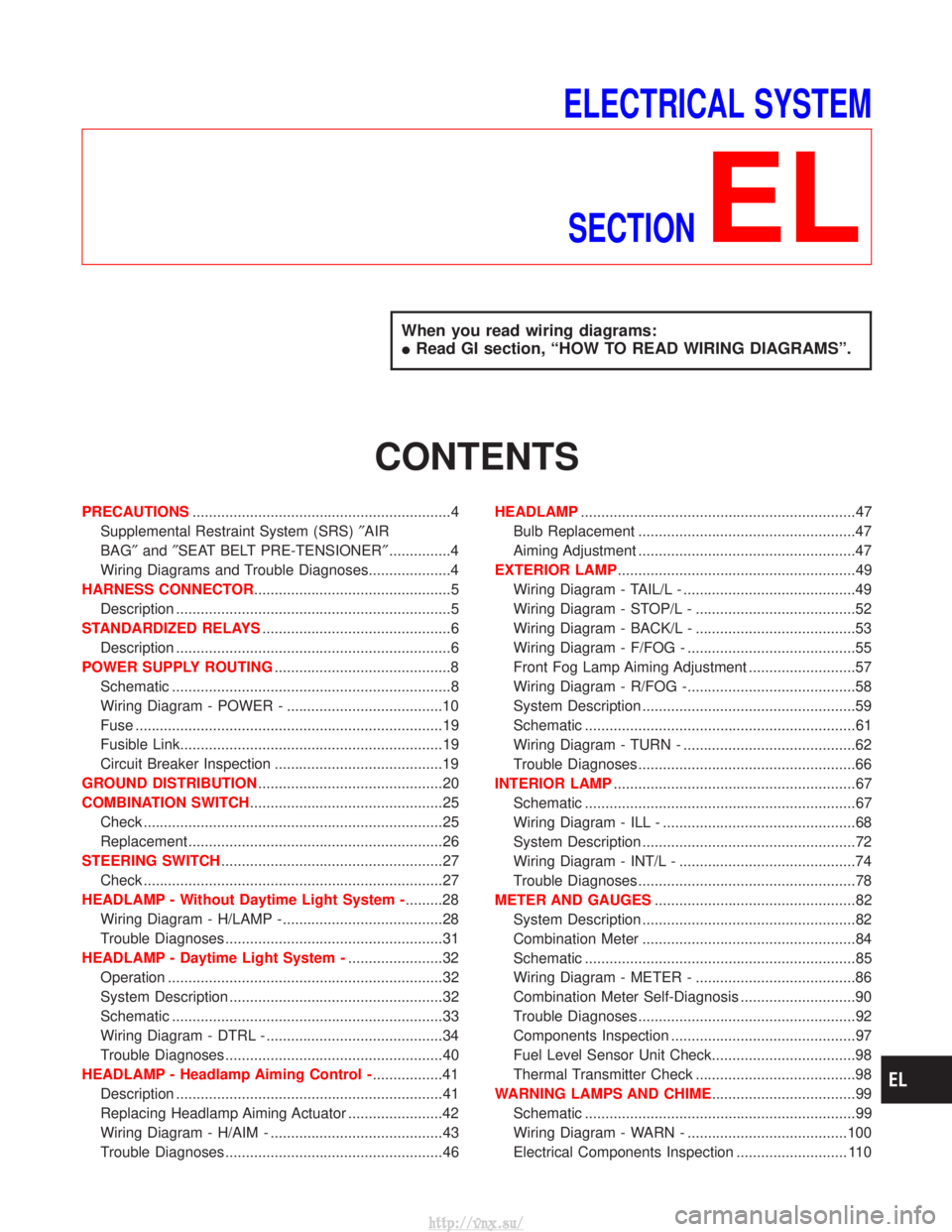
ELECTRICAL SYSTEMSECTION
EL
When you read wiring diagrams:
I Read GI section, ªHOW TO READ WIRING DIAGRAMSº.
CONTENTS
PRECAUTIONS ...............................................................4
Supplemental Restraint System (SRS) ²AIR
BAG² and²SEAT BELT PRE-TENSIONER² ...............4
Wiring Diagrams and Trouble Diagnoses....................4
HARNESS CONNECTOR ................................................5
Description ...................................................................5
STANDARDIZED RELAYS ..............................................6
Description ...................................................................6
POWER SUPPLY ROUTING ...........................................8
Schematic ....................................................................8
Wiring Diagram - POWER - ......................................10
Fuse ........................................................................\
...19
Fusible Link................................................................19
Circuit Breaker Inspection .........................................19
GROUND DISTRIBUTION .............................................20
COMBINATION SWITCH ...............................................25
Check ........................................................................\
.25
Replacement ..............................................................26
STEERING SWITCH ......................................................27
Check ........................................................................\
.27
HEADLAMP - Without Daytime Light System - .........28
Wiring Diagram - H/LAMP -.......................................28
Trouble Diagnoses.....................................................31
HEADLAMP - Daytime Light System - .......................32
Operation ...................................................................32
System Description ....................................................32
Schematic ..................................................................33
Wiring Diagram - DTRL - ...........................................34
Trouble Diagnoses.....................................................40
HEADLAMP - Headlamp Aiming Control - .................41
Description .................................................................41
Replacing Headlamp Aiming Actuator .......................42
Wiring Diagram - H/AIM - ..........................................43
Trouble Diagnoses.....................................................46 HEADLAMP
...................................................................47
Bulb Replacement .....................................................47
Aiming Adjustment .....................................................47
EXTERIOR LAMP ..........................................................49
Wiring Diagram - TAIL/L - ..........................................49
Wiring Diagram - STOP/L - .......................................52
Wiring Diagram - BACK/L - .......................................53
Wiring Diagram - F/FOG - .........................................55
Front Fog Lamp Aiming Adjustment ..........................57
Wiring Diagram - R/FOG -.........................................58
System Description ....................................................59
Schematic ..................................................................61
Wiring Diagram - TURN - ..........................................62
Trouble Diagnoses.....................................................66
INTERIOR LAMP ...........................................................67
Schematic ..................................................................67
Wiring Diagram - ILL - ...............................................68
System Description ....................................................72
Wiring Diagram - INT/L - ...........................................74
Trouble Diagnoses.....................................................78
METER AND GAUGES .................................................82
System Description ....................................................82
Combination Meter ....................................................84
Schematic ..................................................................85
Wiring Diagram - METER - .......................................86
Combination Meter Self-Diagnosis ............................90
Trouble Diagnoses.....................................................92
Components Inspection .............................................97
Fuel Level Sensor Unit Check...................................98
Thermal Transmitter Check .......................................98
WARNING LAMPS AND CHIME ...................................99
Schematic ..................................................................99
Wiring Diagram - WARN - .......................................100
Electrical Components Inspection ........................... 110
http://vnx.su/
Page 1830 of 1833
INT/V - Wiring diagram ................................EC-282
Intake air control valve control solenoidvalve .........................................................EC-281
Intake Air Volume .........................................EC-150
Intake door control linkage adjustment ..........HA-63
Intake manifold...............................................EM-12
Interior .............................................................BT-18
Interior lamp ..............................................EL-67, 74
Interior lamp on-off control..............................EL-73
ISO 15031-2 Terminology................................GI-34
K
Knuckle spindle ...............................................FA-20 L
License lamp ...................................................EL-49
Limited slip diff. adjustment............................PD-45
Limited slip diff. assembly ..............................PD-47
Limited slip diff. disassembly ...................PD-43, 44
Limited slip diff. inspection .............................PD-44
Line pressure solenoid valve ..........................AT-86
Line pressure test (A/T) ..........................AT-30, 201
Liquid gasket application .................................EM-3
Location of electrical units ............EL-275, 276, 278
Lock, door ...........................................BT-10, 12, 14
Low and reverse brake .................................AT-166
LSV (Load sensing valve) ..............................BR-10
Lubricants.......................................................MA-17
Lubrication circuit (engine) .........................LC-3, 20
Lubrication oil A/C (checking andadjusting) ....................................................HA-22
Lubrication oil A/C (SDS) ...............................HA-64
Lubrication-locks, hinges and hood latches ..................................................MA-36, 45
Luggage compartment trim .............................BT-18
M
MAFS - Wiring diagram..................................EC-90
MAIN - Wiring diagram...................................EC-80
Main drive gear (M/T) .....................................MT-11
Main gear (Transfer) .................................TF-10, 21
Mainshaft (M/T) ..............................................MT-11
Mainshaft (Transfer)..................................TF-10, 17
Maintenance ...........MA-5, 8, 11, 14, 20, 36, 48, 49
MAJOR OVERHALL .....................................AT-124
Major overhaul (Transfer) .................................TF-9
Malfunction indicator (MI).......................EC-34, 345
Manifold tightening torque (intake &exhaust) ...............................................MA-20, 28
Manual transmission number ..........................GI-29
Manual transmission oil replacement ......MA-36, 37
Map lamp ........................................................EL-74
Mass air flow sensor (MAFS) ................EC-88, 379
Master cylinder (brake) ..................................BR-17 Meter .........................................................EL-82, 85
METER - Wiring diagram................................EL-86
MIL/DL - Wiring diagram ..............................EC-310
MIRROR - Wiring diagram............................EL-154
Mirror, door......................................................BT-48
Model variation ................................................GI-27
Molding - See Exterior ....................................BT-21
M/T major overhaul ........................................MT-10
M/T removal and installation ........................MT-7, 8
Mud guard - See Exterior ...............................BT-21
MULTI - Wiring diagram................................EL-205
Multi-remote control
system ..............................EL-202, 204, 213, 215
Multiport fuel injection precautions ....................GI-5
N
NATS (Nissan anti-theftsystem) .....................EL-222, 223, 224, 231, 242
NATS - Wiring diagram .................................EL-225
NATS V2.0 precautions (For Europe) ...............GI-4
Needle lift sensor .........................................EC-450
NVH troubleshooting (EM) ...............................EM-8
O
Oil change (capacity) ............MA-21, 29, 37, 38, 39
Oil change (interval) ..................................MA-5, 35
Oil cooler (engine) ............................................LC-8
Oil pan (engine) .............................................EM-22
Oil pump (A/T)...............................................AT-139
Oil seal replacement (engine)........................EM-50
Oil seal replacement (front final drive4WD)...........................................................PD-10
OILPSW - Wiring diagram............................EC-474
On board diagnostic system ..................EC-33, 344
Overdrive control switch................................AT-100
Overheat .......................................................EC-109
Overrun clutch solenoid valve ..................AT-71, 72
Oversize piston ..............................................EM-74
P
Park/Neutral position switch .........................EC-256
Park/neutral position switch (A/T) ...........AT-93, 119
Parking drum brake ........................................BR-36
Parking lamp ...................................................EL-49
PCV (positive crankcase ventilation) .....EC-23, 335
Periodic maintenance ......................................MA-5
Piston pin inspection ......................................EM-71
Piston ring inspection.....................................EM-72
PNP/SW - Wiring diagram ...........................EC-257
POWER - Wiring diagram...............................EL-10
Power doorlock ...........EL-163, 164, 171, 179, 180, 182, 192
Power steering fluid level...............MA-36, 44, ST-4
Power steering gear .................................ST-12, 22
ALPHABETICAL INDEX
IDX-5
http://vnx.su/