Page 46 of 579

jB
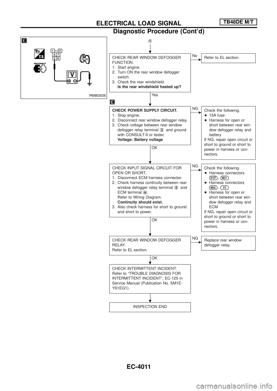
CHECK REAR WINDOW DEFOGGER
FUNCTION.
1. Start engine.
2. Turn ON the rear window defogger
switch.
3. Check the rear windshield.
Is the rear windshield heated up?
Ye s
cNo
Refer to EL section.
CHECK POWER SUPPLY CIRCUIT.
1. Stop engine.
2. Disconnect rear window defogger relay.
3. Check voltage between rear window
defogger relay terminalj
3and ground
with CONSULT-II or tester.
Voltage: Battery voltage
OK
cNG
Check the following.
+15A fuse
+Harness for open or
short between rear win-
dow defogger relay and
battery
If NG, repair open circuit or
short to ground or short to
power in harness or con-
nectors.
CHECK INPUT SIGNAL CIRCUIT FOR
OPEN OR SHORT.
1. Disconnect ECM harness connector.
2. Check harness continuity between rear
window defogger relay terminalj
5and
ECM terminalj
96.
Refer to Wiring Diagram.
Continuity should exist.
3. Also check harness for short to ground
and short to power.
OK
cNG
Check the following.
+Harness connectors
E127,M21
+Harness connectors
M50,F5
+Harness for open or
short between rear win-
dow defogger relay and
ECM
If NG, repair open circuit or
short to ground or short to
power in harness or con-
nectors.
CHECK REAR WINDOW DEFOGGER
RELAY.
Refer to EL section.
OK
cNG
Replace rear window
defogger relay.
CHECK INTERMITTENT INCIDENT.
Refer to ªTROUBLE DIAGNOSIS FOR
INTERMITTENT INCIDENTº, EC-125 in
Service Manual (Publication No. SM1E-
Y61EG1).
INSPECTION END
PBIB0302E
.
.
.
.
.
.
ELECTRICAL LOAD SIGNALTB48DE M/T
Diagnostic Procedure (Cont'd)
EC-4011
Page 47 of 579

jC
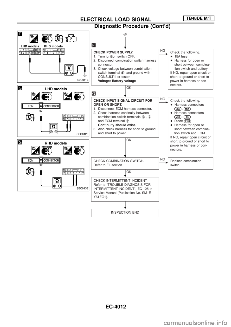
CHECK POWER SUPPLY.
1. Turn ignition switch OFF.
2. Disconnect combination switch harness
connector.
3. Check voltage between combination
switch terminalj
5and ground with
CONSULT-II or tester.
Voltage: Battery voltage
OK
cNG
Check the following.
+15A fuse
+Harness for open or
short between combina-
tion switch and battery
If NG, repair open circuit or
short to ground or short to
power in harness or con-
nectors.
CHECK INPUT SIGNAL CIRCUIT FOR
OPEN OR SHORT.
1. Disconnect ECM harness connector.
2. Check harness continuity between
combination switch terminalsj
6,j7
and ECM terminalj97.
Continuity should exist.
3. Also check harness for short to ground
and short to power.
OK
cNG
Check the following.
+Harness connectors
E127,M21
+Harness connectors
M50,F5
+DiodeE108
+Harness for open or
short between combina-
tion switch and ECM
If NG, repair open circuit or
short to ground or short to
power in harness or con-
nectors.
CHECK COMBINATION SWITCH.
Refer to EL section.
OK
cNG
Replace combination
switch.
CHECK INTERMITTENT INCIDENT.
Refer to ªTROUBLE DIAGNOSIS FOR
INTERMITTENT INCIDENTº, EC-125 in
Service Manual (Publication No. SM1E-
Y61EG1).
INSPECTION END
SEC011E
SEC012E
SEC013E
.
.
.
.
.
ELECTRICAL LOAD SIGNALTB48DE M/T
Diagnostic Procedure (Cont'd)
EC-4012
Page 91 of 579

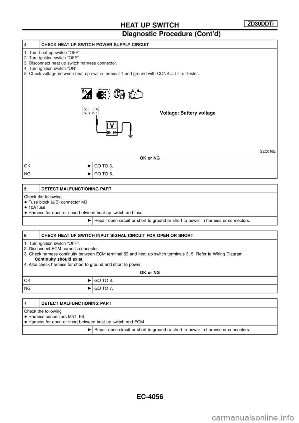
4 CHECK HEAT UP SWITCH POWER SUPPLY CIRCUIT
1. Turn heat up switch ªOFFº.
2. Turn ignition switch ªOFFº.
3. Disconnect heat up switch harness connector.
4. Turn ignition switch ªONº.
5. Check voltage between heat up switch terminal 1 and ground with CONSULT-II or tester.
SEC016E
OK or NG
OKcGO TO 6.
NGcGO TO 5.
5 DETECT MALFUNCTIONING PART
Check the following.
+Fuse block (J/B) connector M3
+10A fuse
+Harness for open or short between heat up switch and fuse
cRepair open circuit or short to ground or short to power in harness or connectors.
6 CHECK HEAT UP SWITCH INPUT SIGNAL CIRCUIT FOR OPEN OR SHORT
1. Turn ignition switch ªOFFº.
2. Disconnect ECM harness connector.
3. Check harness continuity between ECM terminal 59 and heat up switch terminals 3, 5. Refer to Wiring Diagram.
Continuity should exist.
4. Also check harness for short to ground and short to power.
OK or NG
OKcGO TO 8.
NGcGO TO 7.
7 DETECT MALFUNCTIONING PART
Check the following.
+Harness connectors M51, F6
+Harness for open or short between heat up switch and ECM
cRepair open circuit or short to ground or short to power in harness or connectors.
HEAT UP SWITCHZD30DDTi
Diagnostic Procedure (Cont'd)
EC-4056
Page 293 of 579
Trouble Diagnoses
POWER SUPPLY AND GROUND CIRCUIT CHECK FOR NAVI CONTROL UNIT
1. CHECK FUSE
Make sure that the following fuses of the NAVI control unit are not blown.OK or NG
OK ©GO TO 2.
NG ©If fuse is blown, be sure to eliminate cause of malfunction before installing new fuse.
Refer to EL-4005 in ªPOWER SUPPLY ROUTINGº.
Terminals
Power source Fuse No.
Connector Terminal (wire color)
NAVI control unit M167 2 (R/G)
Battery 56
3 (R/G)
6 (L/OR) Ignition switch ACC or ON 10
2. CHECK POWER SUPPLY CIRCUIT
Check voltage between NAVI control unit and ground.
SKIA8719E
OK or NG
OK ©GO TO 3.
NG ©Repair or replace harness.
Terminals
OFF ACC ON
(+)
(þ)
Connector Terminal (wire color)
NAVI control unit M167 2 (R/G)
GroundBattery voltage Battery voltage Battery voltage
3 (R/G) Battery voltage Battery voltage Battery voltage
6 (L/OR) 0V Battery voltage Battery voltage
NAVIGATION SYSTEM
EL-4198
Page 294 of 579
3. CHECK GROUND CIRCUIT
1. Turn ignition switch OFF.
2. Disconnect NAVI control unit connector.
3. Check continuity between NAVI control unit and ground.
SKIA8720E
OK or NG
OK ©INSPECTION END
NG ©Repair or replace harness.
Terminals
Continuity
(+)
(þ)
Connector Terminal (wire color)
NAVI control unit M167 1 (B)
Ground Yes
4 (B)
POWER SUPPLY AND GROUND CIRCUIT CHECK FOR DISPLAY
1. CHECK FUSE
Make sure that the following fuses of the display are not blown.
OK or NG
OK ©GO TO 2.
NG ©If fuse is blown, be sure to eliminate cause of malfunction before installing new fuse.
Refer to EL-4005 in ªPOWER SUPPLY ROUTINGº.
Unit Terminals
Power source Fuse No.
Connector Terminal (wire color)
Display M170 21 (R/G)
Battery 56
23 (R/G)
19 (L/OR) Ignition switch ACC or ON 10
NAVIGATION SYSTEM
Trouble Diagnoses (Cont'd)
EL-4199
Page 296 of 579
POWER SUPPLY AND GROUND CIRCUIT CHECK FOR NAVI SWITCH
1. CHECK FUSE
Check 10A fuse [No. 10, located in fuse block (J/B)].OK or NG
OK ©GO TO 2.
NG ©If fuse is blown, be sure to eliminate cause of malfunction before installing new fuse.
Refer to EL-4005 in ªPOWER SUPPLY ROUTINGº.
2. CHECK POWER SUPPLY CIRCUIT
Check voltage between NAVI switch and ground.
SKIA8724E
OK or NG
OK ©GO TO 3.
NG ©Repair or replace harness.
Unit Terminals
OFF ACC ON
(+)
(þ)
Connector Terminal (wire
color)
NAVI switch M169 1 (L/OR) Ground 0V Battery voltage Battery voltage
3. CHECK GROUND CIRCUIT
1. Turn ignition switch OFF.
2. Disconnect NAVI switch connector.
3. Check continuity between NAVI switch harness connector M169 terminal 7 (B) and ground.
SKIA8725E
Continuity should exist. OK or NG
OK ©INSPECTION END
NG ©Repair or replace harness.
NAVIGATION SYSTEM
Trouble Diagnoses (Cont'd)
EL-4201
Page 297 of 579
POWER SUPPLY AND GROUND CIRCUIT CHECK FOR TRANSFER UNIT
1. CHECK FUSE
Make sure that the following fuses of the transfer unit are not blown.OK or NG
OK ©GO TO 2.
NG ©If fuse is blown, be sure to eliminate cause of malfunction before installing new fuse.
Refer to EL-4005 in ªPOWER SUPPLY ROUTINGº.
Unit Terminals
Power source Fuse No.
Connector Terminal (wire color)
Transfer unit M173 31 (R/G)
Battery 56
32 (R/G)
29 (L/OR) Ignition switch ACC or ON 10
2. CHECK POWER SUPPLY CIRCUIT
Check voltage between transfer unit and ground.
SKIA9079E
OK or NG
OK ©GO TO 3.
NG ©Repair or replace harness.
Unit Terminals
OFF ACC ON
(+)
(þ)
Connector Terminal (wire
color)
Transfer unit M173 31 (R/G)
GroundBattery voltage Battery voltage Battery voltage
32 (R/G) Battery voltage Battery voltage Battery voltage
29 (L/OR) 0V Battery voltage Battery voltage
NAVIGATION SYSTEM
Trouble Diagnoses (Cont'd)
EL-4202
Page 303 of 579
IGNITION SIGNAL CHECK
1. CHECK IGNITION SIGNAL
1. Turn ignition switch ON.
2. Check voltage between NAVI control unit harness connector M168 terminal 26 (R/W) and ground.
SKIA9108E
26 (R/W) - Ground: Battery voltageOK or NG
OK ©Replace NAVI control unit.
NG ©Check the following.
+10A fuse [No. 28, located in fuse block (J/B)]
+ Harness for open or short between NAVI control unit and fuse
REVERSE SIGNAL CHECK
1. CHECK REVERSE LAMP
1. Turn ignition switch ON.
Ð With the A/T selector lever in R position, does ªRº in the shift position indicator turned on? (With A/T)
Ð With the shift lever in R position. Are reverse lamps turned on? (With M/T)
YesorNo
Ye s ©GO TO 2.
No ©Check ªBACK-UP LAMPº system.
NAVIGATION SYSTEM
Trouble Diagnoses (Cont'd)
EL-4208