Page 44 of 579
Diagnostic Procedure
INSPECTION START
Do you have CONSULT-II?
Ye s
cNo
Go tojA. (Without CON-
SULT-II)
CHECK OVERALL FUNCTION-I.
With CONSULT-II
1. Turn ignition switch ON.
2. Check ªLOAD SIGNALº in ªDATA
MONITORº mode with CONSULT-II.
Rear window defogger ON
LOAD SIGNAL: ON
Rear window defogger OFF
LOAD SIGNAL: OFF
OK
cNG
Check rear window defog-
ger circuit. (Go toj
B.)
CHECK OVERALL FUNCTION-II.
With CONSULT-II
Check ªLOAD SIGNALº in ªDATA MONI-
TORº mode with CONSULT-II.
Lighting switch ON at 2nd position
LOAD SIGNAL: ON
Lighting switch OFF
LOAD SIGNAL: OFF
OK
cNG
Check lighting switch cir-
cuit. (Go toj
C.)
INSPECTION END
PBIB0103E
PBIB0296E
PBIB0103E
PBIB0296E
.
.
.
.
ELECTRICAL LOAD SIGNALTB48DE M/T
EC-4009
Page 45 of 579
jA
CHECK OVERALL FUNCTION-I.
Without CONSULT-II
1. Turn ignition switch ON.
2. Check voltage between ECM terminal
j
96and ground with tester.
Rear window defogger ON
Voltage: Battery voltage
Rear window defogger OFF
Voltage: 0V
OK
cNG
Check rear window defog-
ger circuit. (Go toj
B.)
CHECK OVERALL FUNCTION-II.
Without CONSULT-II
Check voltage between ECM terminalj
97
and ground with tester.
Lighting switch ON at 2nd position
Voltage: Battery voltage
Lighting switch OFF
Voltage: 0V
OK
cNG
Check lighting switch cir-
cuit. (Go toj
C.)
INSPECTION END
SEC022E
SEC010E
.
.
.
ELECTRICAL LOAD SIGNALTB48DE M/T
Diagnostic Procedure (Cont'd)
EC-4010
Page 46 of 579

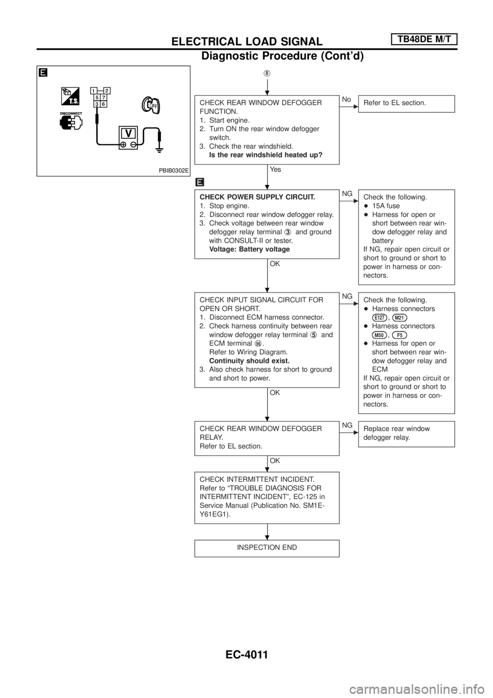
jB
CHECK REAR WINDOW DEFOGGER
FUNCTION.
1. Start engine.
2. Turn ON the rear window defogger
switch.
3. Check the rear windshield.
Is the rear windshield heated up?
Ye s
cNo
Refer to EL section.
CHECK POWER SUPPLY CIRCUIT.
1. Stop engine.
2. Disconnect rear window defogger relay.
3. Check voltage between rear window
defogger relay terminalj
3and ground
with CONSULT-II or tester.
Voltage: Battery voltage
OK
cNG
Check the following.
+15A fuse
+Harness for open or
short between rear win-
dow defogger relay and
battery
If NG, repair open circuit or
short to ground or short to
power in harness or con-
nectors.
CHECK INPUT SIGNAL CIRCUIT FOR
OPEN OR SHORT.
1. Disconnect ECM harness connector.
2. Check harness continuity between rear
window defogger relay terminalj
5and
ECM terminalj
96.
Refer to Wiring Diagram.
Continuity should exist.
3. Also check harness for short to ground
and short to power.
OK
cNG
Check the following.
+Harness connectors
E127,M21
+Harness connectors
M50,F5
+Harness for open or
short between rear win-
dow defogger relay and
ECM
If NG, repair open circuit or
short to ground or short to
power in harness or con-
nectors.
CHECK REAR WINDOW DEFOGGER
RELAY.
Refer to EL section.
OK
cNG
Replace rear window
defogger relay.
CHECK INTERMITTENT INCIDENT.
Refer to ªTROUBLE DIAGNOSIS FOR
INTERMITTENT INCIDENTº, EC-125 in
Service Manual (Publication No. SM1E-
Y61EG1).
INSPECTION END
PBIB0302E
.
.
.
.
.
.
ELECTRICAL LOAD SIGNALTB48DE M/T
Diagnostic Procedure (Cont'd)
EC-4011
Page 47 of 579

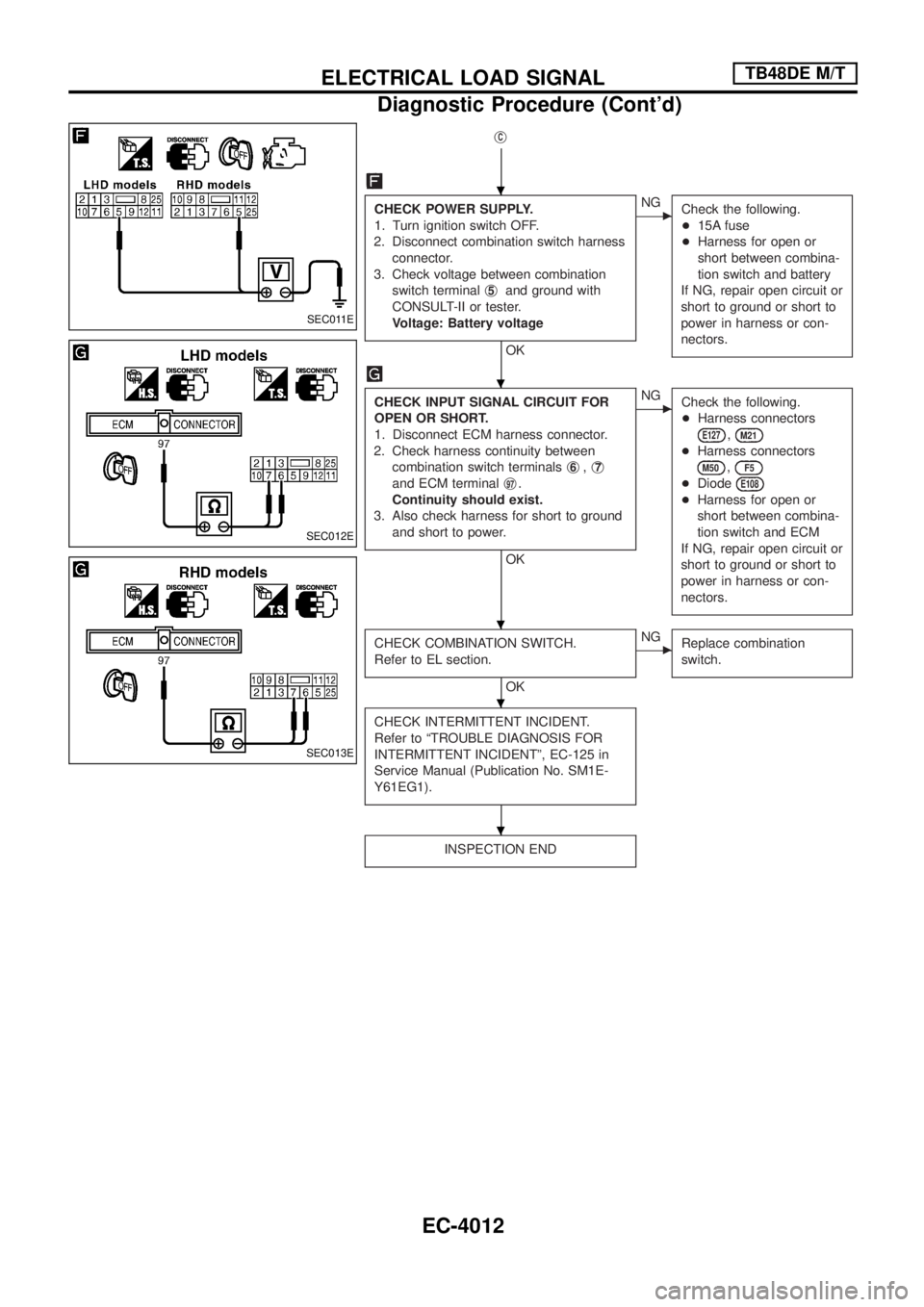
jC
CHECK POWER SUPPLY.
1. Turn ignition switch OFF.
2. Disconnect combination switch harness
connector.
3. Check voltage between combination
switch terminalj
5and ground with
CONSULT-II or tester.
Voltage: Battery voltage
OK
cNG
Check the following.
+15A fuse
+Harness for open or
short between combina-
tion switch and battery
If NG, repair open circuit or
short to ground or short to
power in harness or con-
nectors.
CHECK INPUT SIGNAL CIRCUIT FOR
OPEN OR SHORT.
1. Disconnect ECM harness connector.
2. Check harness continuity between
combination switch terminalsj
6,j7
and ECM terminalj97.
Continuity should exist.
3. Also check harness for short to ground
and short to power.
OK
cNG
Check the following.
+Harness connectors
E127,M21
+Harness connectors
M50,F5
+DiodeE108
+Harness for open or
short between combina-
tion switch and ECM
If NG, repair open circuit or
short to ground or short to
power in harness or con-
nectors.
CHECK COMBINATION SWITCH.
Refer to EL section.
OK
cNG
Replace combination
switch.
CHECK INTERMITTENT INCIDENT.
Refer to ªTROUBLE DIAGNOSIS FOR
INTERMITTENT INCIDENTº, EC-125 in
Service Manual (Publication No. SM1E-
Y61EG1).
INSPECTION END
SEC011E
SEC012E
SEC013E
.
.
.
.
.
ELECTRICAL LOAD SIGNALTB48DE M/T
Diagnostic Procedure (Cont'd)
EC-4012
Page 53 of 579
Diagnostic Procedure
1 CHECK LOAD SIGNAL CIRCUIT OVERALL FUNCTION-I
With CONSULT-II
1. Turn ignition switch ªONº.
2. Connect CONSULT-II and select ªDATA MONITORº mode.
3. Select ªLOAD SIGNALº and check indication under the following conditions.
PBIB0103E
MTBL1594
OK or NG
OKcGO TO 2.
NGcGO TO 3.
ELECTRICAL LOAD SIGNALTB48DE A/T
EC-4018
Page 54 of 579

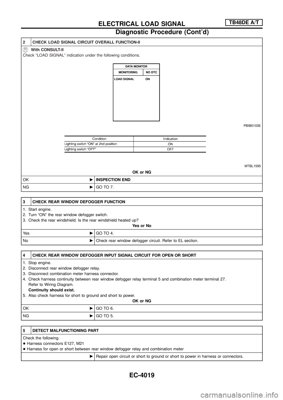
2 CHECK LOAD SIGNAL CIRCUIT OVERALL FUNCTION-II
With CONSULT-II
Check ªLOAD SIGNALº indication under the following conditions.
PBIB0103E
MTBL1595
OK or NG
OKcINSPECTION END
NGcGO TO 7.
3 CHECK REAR WINDOW DEFOGGER FUNCTION
1. Start engine.
2. Turn ªONº the rear window defogger switch.
3. Check the rear windshield. Is the rear windshield heated up?
YesorNo
Ye scGO TO 4.
NocCheck rear window defogger circuit. Refer to EL section.
4 CHECK REAR WINDOW DEFOGGER INPUT SIGNAL CIRCUIT FOR OPEN OR SHORT
1. Stop engine.
2. Disconnect rear window defogger relay.
3. Disconnect combination meter harness connector.
4. Check harness continuity between rear window defogger relay terminal 5 and combination meter terminal 27.
Refer to Wiring Diagram.
Continuity should exist.
5. Also check harness for short to ground and short to power.
OK or NG
OKcGO TO 6.
NGcGO TO 5.
5 DETECT MALFUNCTIONING PART
Check the following.
+Harness connectors E127, M21
+Harness for open or short between rear window defogger relay and combination meter
cRepair open circuit or short to ground or short to power in harness or connectors.
ELECTRICAL LOAD SIGNALTB48DE A/T
Diagnostic Procedure (Cont'd)
EC-4019
Page 62 of 579
Diagnostic Procedure
1 CHECK LOAD SIGNAL CIRCUIT OVERALL FUNCTION-I
With CONSULT-II
With GST
1. Turn ignition switch ªONº.
2. Connect CONSULT-II or GST and select ªDATA MONITORº mode.
3. Select ªLOAD SIGNALº and check indication under the following conditions.
PBIB0103E
MTBL1594
OK or NG
OKcGO TO 2.
NGcGO TO 3.
ELECTRICAL LOAD
SIGNALTB48DE A/T (WITH EURO-OBD)
EC-4027
Page 63 of 579

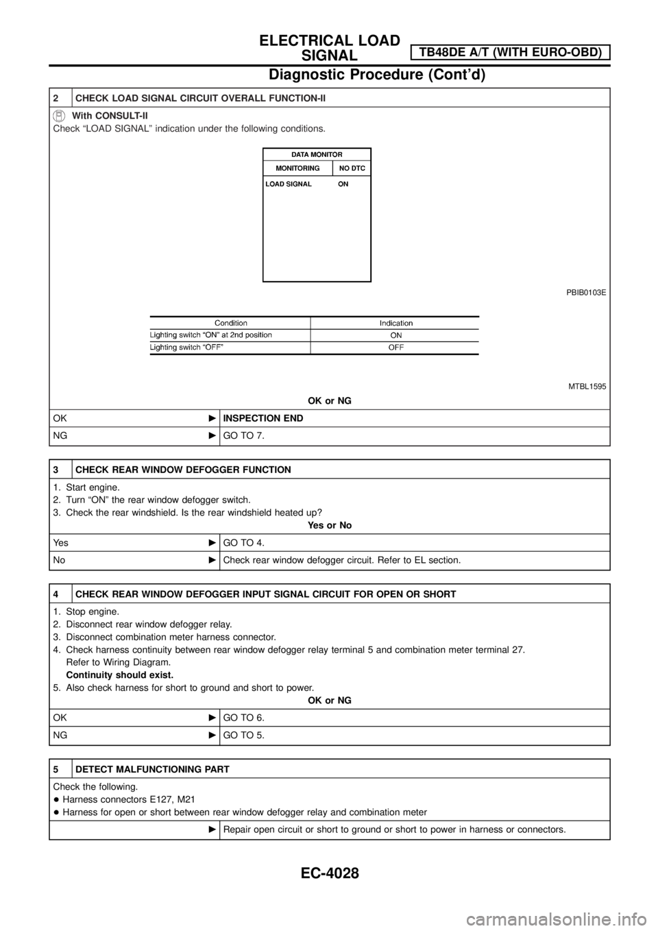
2 CHECK LOAD SIGNAL CIRCUIT OVERALL FUNCTION-II
With CONSULT-II
Check ªLOAD SIGNALº indication under the following conditions.
PBIB0103E
MTBL1595
OK or NG
OKcINSPECTION END
NGcGO TO 7.
3 CHECK REAR WINDOW DEFOGGER FUNCTION
1. Start engine.
2. Turn ªONº the rear window defogger switch.
3. Check the rear windshield. Is the rear windshield heated up?
YesorNo
Ye scGO TO 4.
NocCheck rear window defogger circuit. Refer to EL section.
4 CHECK REAR WINDOW DEFOGGER INPUT SIGNAL CIRCUIT FOR OPEN OR SHORT
1. Stop engine.
2. Disconnect rear window defogger relay.
3. Disconnect combination meter harness connector.
4. Check harness continuity between rear window defogger relay terminal 5 and combination meter terminal 27.
Refer to Wiring Diagram.
Continuity should exist.
5. Also check harness for short to ground and short to power.
OK or NG
OKcGO TO 6.
NGcGO TO 5.
5 DETECT MALFUNCTIONING PART
Check the following.
+Harness connectors E127, M21
+Harness for open or short between rear window defogger relay and combination meter
cRepair open circuit or short to ground or short to power in harness or connectors.
ELECTRICAL LOAD
SIGNALTB48DE A/T (WITH EURO-OBD)
Diagnostic Procedure (Cont'd)
EC-4028