2004 NISSAN PATROL turn signal
[x] Cancel search: turn signalPage 313 of 579
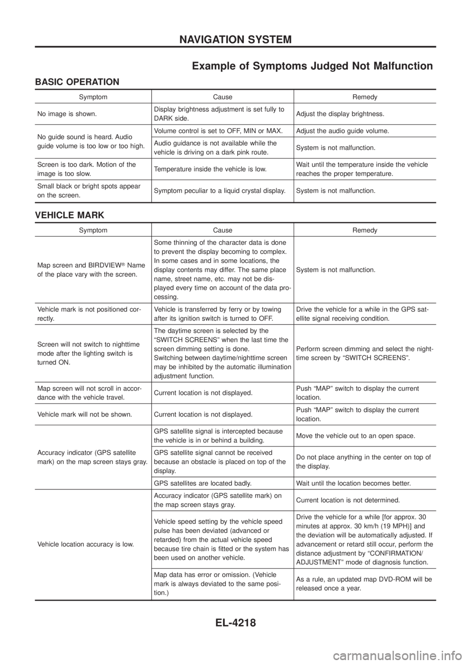
Example of Symptoms Judged Not Malfunction
BASIC OPERATION
Symptom Cause Remedy
No image is shown. Display brightness adjustment is set fully to
DARK side. Adjust the display brightness.
No guide sound is heard. Audio
guide volume is too low or too high. Volume control is set to OFF, MIN or MAX. Adjust the audio guide volume.
Audio guidance is not available while the
vehicle is driving on a dark pink route.
System is not malfunction.
Screen is too dark. Motion of the
image is too slow. Temperature inside the vehicle is low. Wait until the temperature inside the vehicle
reaches the proper temperature.
Small black or bright spots appear
on the screen. Symptom peculiar to a liquid crystal display. System is not malfunction.
VEHICLE MARK
Symptom Cause Remedy
Map screen and BIRDVIEW TName
of the place vary with the screen. Some thinning of the character data is done
to prevent the display becoming to complex.
In some cases and in some locations, the
display contents may differ. The same place
name, street name, etc. may not be dis-
played every time on account of the data pro-
cessing.
System is not malfunction.
Vehicle mark is not positioned cor-
rectly. Vehicle is transferred by ferry or by towing
after its ignition switch is turned to OFF. Drive the vehicle for a while in the GPS sat-
ellite signal receiving condition.
Screen will not switch to nighttime
mode after the lighting switch is
turned ON. The daytime screen is selected by the
ªSWITCH SCREENSº when the last time the
screen dimming setting is done.
Switching between daytime/nighttime screen
may be inhibited by the automatic illumination
adjustment function.
Perform screen dimming and select the night-
time screen by ªSWITCH SCREENSº.
Map screen will not scroll in accor-
dance with the vehicle travel. Current location is not displayed. Push ªMAPº switch to display the current
location.
Vehicle mark will not be shown. Current location is not displayed. Push ªMAPº switch to display the current
location.
Accuracy indicator (GPS satellite
mark) on the map screen stays gray. GPS satellite signal is intercepted because
the vehicle is in or behind a building.
Move the vehicle out to an open space.
GPS satellite signal cannot be received
because an obstacle is placed on top of the
display. Do not place anything in the center on top of
the display.
GPS satellites are located badly. Wait until the location becomes better.
Vehicle location accuracy is low. Accuracy indicator (GPS satellite mark) on
the map screen stays gray.
Current location is not determined.
Vehicle speed setting by the vehicle speed
pulse has been deviated (advanced or
retarded) from the actual vehicle speed
because tire chain is ®tted or the system has
been used on another vehicle. Drive the vehicle for a while [for approx. 30
minutes at approx. 30 km/h (19 MPH)] and
the deviation will be automatically adjusted. If
advancement or retard still occur, perform the
distance adjustment by ªCONFIRMATION/
ADJUSTMENTº mode of diagnosis function.
Map data has error or omission. (Vehicle
mark is always deviated to the same posi-
tion.) As a rule, an updated map DVD-ROM will be
released once a year.
NAVIGATION SYSTEM
EL-4218
Page 318 of 579
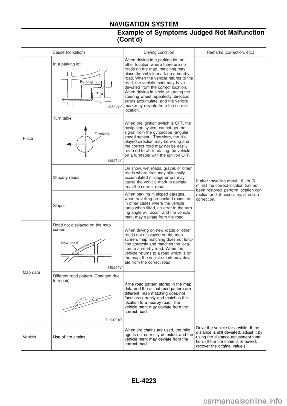
Cause (condition) Driving condition Remarks (correction, etc.)
Place In a parking lot
SEL709V
When driving in a parking lot, or
other location where there are no
roads on the map, matching may
place the vehicle mark on a nearby
road. When the vehicle returns to the
road, the vehicle mark may have
deviated from the correct location.
When driving in circle or turning the
steering wheel repeatedly, direction
errors accumulate, and the vehicle
mark may deviate from the correct
location.
If after travelling about 10 km (6
miles) the correct location has not
been restored, perform location cor-
rection and, if necessary, direction
correction.
Turn table
SEL710V
When the ignition switch is OFF, the
navigation system cannot get the
signal from the gyroscope (angular
speed sensor). Therefore, the dis-
played direction may be wrong and
the correct road may not be easily
returned to after rotating the vehicle
on a turntable with the ignition OFF.
Slippery roads On snow, wet roads, gravel, or other
roads where tires may slip easily,
accumulated mileage errors may
cause the vehicle mark to deviate
from the correct road.
Slopes When parking in sloped garages,
when travelling on banked roads, or
in other cases where the vehicle
turns when tilted, an error in the turn-
ing angle will occur, and the vehicle
mark may deviate from the road.
Map data Road not displayed on the map
screen
SEL699V
When driving on new roads or other
roads not displayed on the map
screen, map matching does not func-
tion correctly and matches the loca-
tion to a nearby road. When the
vehicle returns to a road which is on
the map, the vehicle mark may devi-
ate from the correct road.
Different road pattern (Changed due
to repair)
ELK0201D
If the road pattern stored in the map
data and the actual road pattern are
different, map matching does not
function correctly and matches the
location to a nearby road. The
vehicle mark may deviate from the
correct road.
Vehicle Use of tire chains When tire chains are used, the mile-
age is not correctly detected, and the
vehicle mark may deviate from the
correct road.Drive the vehicle for a while. If the
distance is still deviated, adjust it by
using the distance adjustment func-
tion. (If the tire chain is removed,
recover the original value.)
NAVIGATION SYSTEM
Example of Symptoms Judged Not Malfunction
(Cont'd)
EL-4223
Page 442 of 579
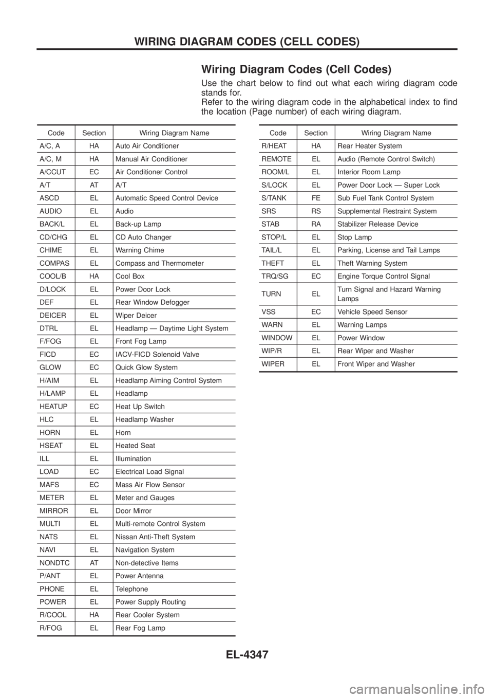
Wiring Diagram Codes (Cell Codes)
Use the chart below to ®nd out what each wiring diagram code
stands for.
Refer to the wiring diagram code in the alphabetical index to ®nd
the location (Page number) of each wiring diagram.
Code Section Wiring Diagram Name
A/C, A HA Auto Air Conditioner
A/C, M HA Manual Air Conditioner
A/CCUT EC Air Conditioner Control
A/T AT A/T
ASCD EL Automatic Speed Control Device
AUDIO EL Audio
BACK/L EL Back-up Lamp
CD/CHG EL CD Auto Changer
CHIME EL Warning Chime
COMPAS EL Compass and Thermometer
COOL/B HA Cool Box
D/LOCK EL Power Door Lock
DEF EL Rear Window Defogger
DEICER EL Wiper Deicer
DTRL EL Headlamp Ð Daytime Light System
F/FOG EL Front Fog Lamp
FICD EC IACV-FICD Solenoid Valve
GLOW EC Quick Glow System
H/AIM EL Headlamp Aiming Control System
H/LAMP EL Headlamp
HEATUP EC Heat Up Switch
HLC EL Headlamp Washer
HORN EL Horn
HSEAT EL Heated Seat
ILL EL Illumination
LOAD EC Electrical Load Signal
MAFS EC Mass Air Flow Sensor
METER EL Meter and Gauges
MIRROR EL Door Mirror
MULTI EL Multi-remote Control System
NATS EL Nissan Anti-Theft System
NAVI EL Navigation System
NONDTC AT Non-detective Items
P/ANT EL Power Antenna
PHONE EL Telephone
POWER EL Power Supply Routing
R/COOL HA Rear Cooler System
R/FOG EL Rear Fog LampCode Section Wiring Diagram Name
R/HEAT HA Rear Heater System
REMOTE EL Audio (Remote Control Switch)
ROOM/L EL Interior Room Lamp
S/LOCK EL Power Door Lock Ð Super Lock
S/TANK FE Sub Fuel Tank Control System
SRS RS Supplemental Restraint System
STAB RA Stabilizer Release Device
STOP/L EL Stop Lamp
TAIL/L EL Parking, License and Tail Lamps
THEFT EL Theft Warning System
TRQ/SG EC Engine Torque Control Signal
TURN EL Turn Signal and Hazard Warning
Lamps
VSS EC Vehicle Speed Sensor
WARN EL Warning Lamps
WINDOW EL Power Window
WIP/R EL Rear Wiper and Washer
WIPER EL Front Wiper and Washer
WIRING DIAGRAM CODES (CELL CODES)
EL-4347
Page 481 of 579
Features (TB48 Engine Models)
CAN COMMUNICATION SYSTEM DESCRIPTION
CAN (Controller Area Network) is a serial communication line for real time application. It is an on-vehicle mul-
tiplex communication line with high data communication speed and excellent error detection ability. Many
electronic control units are equipped onto a vehicle, and each control unit shares information and links with
other control units during operation (not independent). In CAN communication, control units are connected with
2 communication lines (CAN H line, CAN L line) allowing a high rate of information transmission with less wir-
ing. Each control unit transmits/receives data but selectively reads required data only.
SYSTEM CONSTRUCTION
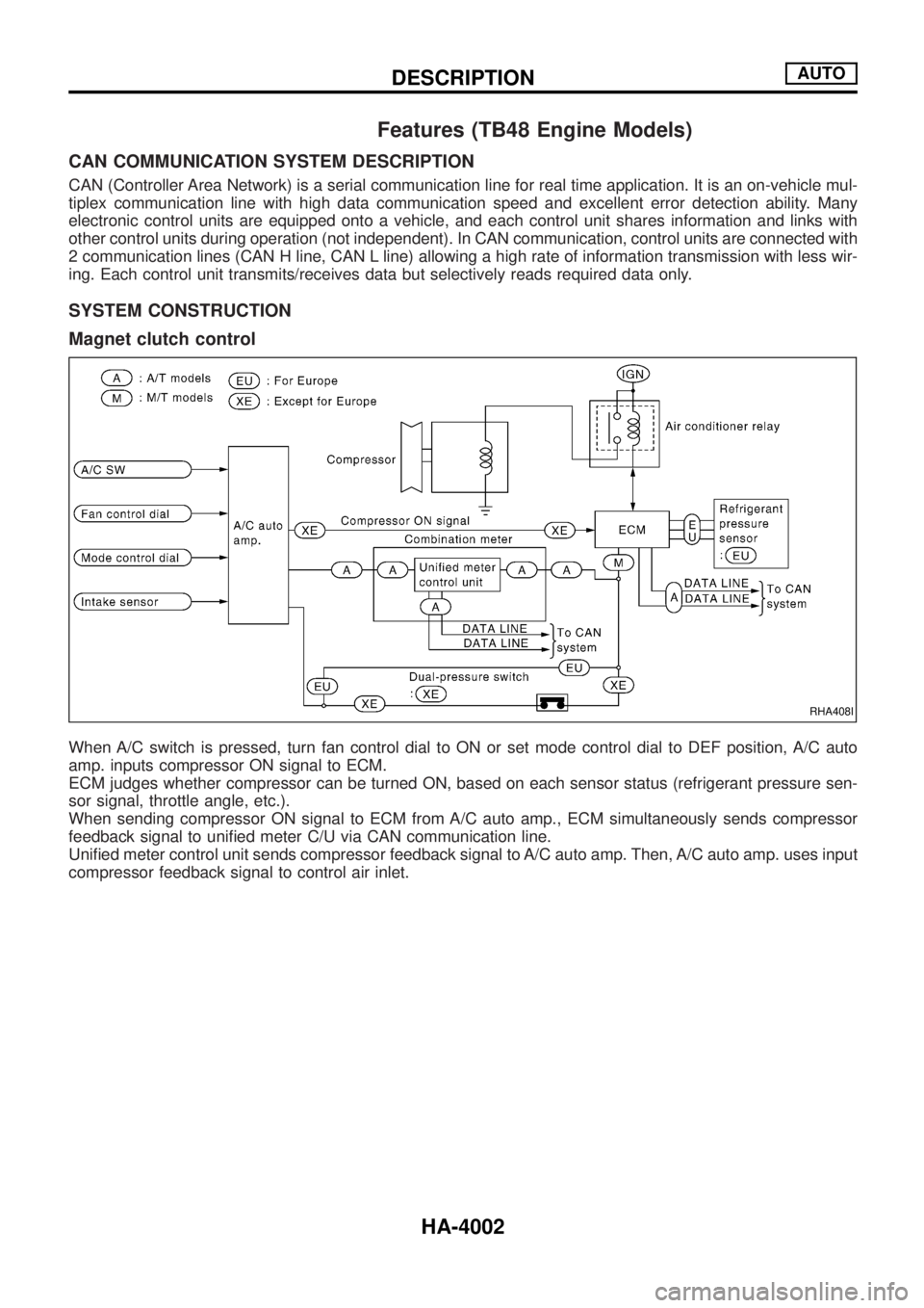
Magnet clutch control
When A/C switch is pressed, turn fan control dial to ON or set mode control dial to DEF position, A/C auto
amp. inputs compressor ON signal to ECM.
ECM judges whether compressor can be turned ON, based on each sensor status (refrigerant pressure sen-
sor signal, throttle angle, etc.).
When sending compressor ON signal to ECM from A/C auto amp., ECM simultaneously sends compressor
feedback signal to uni®ed meter C/U via CAN communication line.
Uni®ed meter control unit sends compressor feedback signal to A/C auto amp. Then, A/C auto amp. uses input
compressor feedback signal to control air inlet.
RHA408I
DESCRIPTIONAUTO
HA-4002
Page 549 of 579
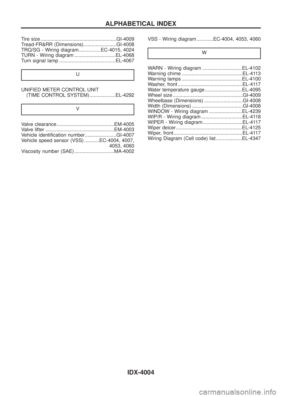
Tire size .......................................................GI-4009
Tread-FR&RR (Dimensions)........................GI-4008
TRQ/SG - Wiring diagram................EC-4015, 4024
TURN - Wiring diagram ..............................EL-4068
Turn signal lamp .........................................EL-4067
U
UNIFIED METER CONTROL UNIT
(TIME CONTROL SYSTEM) ...................EL-4292
V
Valve clearance..........................................EM-4005
Valve lifter ..................................................EM-4003
Vehicle identi®cation number.......................GI-4007
Vehicle speed sensor (VSS) ...........EC-4004, 4007,
4053, 4060
Viscosity number (SAE) .............................MA-4002VSS - Wiring diagram ............EC-4004, 4053, 4060
W
WARN - Wiring diagram .............................EL-4102
Warning chime ............................................EL-4113
Warning lamps ............................................EL-4100
Washer, front ...............................................EL-4117
Water temperature gauge ...........................EL-4095
Wheel size ...................................................GI-4009
Wheelbase (Dimensions) ............................GI-4008
Width (Dimensions) .....................................GI-4008
WINDOW - Wiring diagram ........................EL-4239
WIP/R - Wiring diagram ..............................EL-4118
WIPER - Wiring diagram.............................EL-4117
Wiper deicer ................................................EL-4125
Wiper, front ..................................................EL-4117
Wiring Diagram (Cell code) list ...................EL-4347
ALPHABETICAL INDEX
IDX-4004