Page 170 of 579
Wiring Diagram Ð TURN Ð/Type C
FOR EUROPERear combination lamps are located on rear bumper.
TEL006N
TURN SIGNAL AND HAZARD WARNING LAMPS/WAGON AND HARDTOPMODELS
EL-4075
Page 171 of 579
TEL007N
TURN SIGNAL AND HAZARD WARNING LAMPS/WAGON AND HARDTOPMODELS
Wiring Diagram Ð TURN Ð/Type C (Cont'd)
EL-4076
Page 172 of 579
Wiring Diagram Ð TURN Ð/Type D
FOR AUSTRALIA AND SOUTH AFRICARear combination lamps are located on rear bumper.
TEL008N
TURN SIGNAL AND HAZARD WARNING LAMPS/WAGON AND HARDTOPMODELS
EL-4077
Page 173 of 579
TEL009N
TURN SIGNAL AND HAZARD WARNING LAMPS/WAGON AND HARDTOPMODELS
Wiring Diagram Ð TURN Ð/Type D (Cont'd)
EL-4078
Page 257 of 579

System Description
OUTLINE
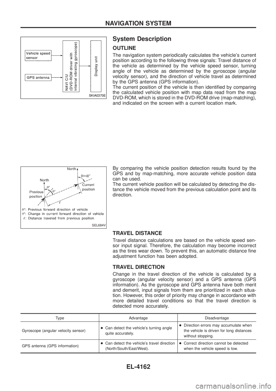
The navigation system periodically calculates the vehicle's current
position according to the following three signals: Travel distance of
the vehicle as determined by the vehicle speed sensor, turning
angle of the vehicle as determined by the gyroscope (angular
velocity sensor), and the direction of vehicle travel as determined
by the GPS antenna (GPS information).
The current position of the vehicle is then identi®ed by comparing
the calculated vehicle position with map data read from the map
DVD-ROM, which is stored in the DVD-ROM drive (map-matching),
and indicated on the screen with a current location mark.
By comparing the vehicle position detection results found by the
GPS and by map-matching, more accurate vehicle position data
can be used.
The current vehicle position will be calculated by detecting the dis-
tance the vehicle moved from the previous calculation point and its
direction.
TRAVEL DISTANCE
Travel distance calculations are based on the vehicle speed sen-
sor input signal. Therefore, the calculation may become incorrect
as the tires wear down. To prevent this, an automatic distance ®ne
adjustment function has been adopted.
TRAVEL DIRECTION
Change in the travel direction of the vehicle is calculated by a
gyroscope (angular velocity sensor) and a GPS antenna (GPS
information). As the gyroscope and GPS antenna have both merit
and demerit, input signals from them are prioritized in each situa-
tion. However, this order of priority may change in accordance with
more detailed travel conditions so that the travel direction is
detected more accurately.
Type Advantage Disadvantage
Gyroscope (angular velocity sensor) +
Can detect the vehicle's turning angle
quite accurately. +
Direction errors may accumulate when
the vehicle is driven for long distances
without stopping.
GPS antenna (GPS information) +
Can detect the vehicle's travel direction
(North/South/East/West). +
Correct direction cannot be detected
when the vehicle speed is low.
SKIA0370E
SEL684V
NAVIGATION SYSTEM
EL-4162
Page 284 of 579

Self-Diagnosis Function
DESCRIPTION
+Diagnosis function consists of the self-diagnosis mode performed automatically and the CONFIRMATION/
ADJUSTMENT mode operated manually.
+ Self-diagnosis mode checks for connections between the units constituting this system, analyzes each
individual unit at the same time, and displays the results on the LCD screen.
+ CONFIRMATION/ADJUSTMENT mode is used to perform trouble diagnosis that require operation and
judgment by an operator (malfunction that cannot be automatically judged by the system), to check/change
the set value, and to display the History of Errors of the navigation system.
DIAGNOSIS ITEM
Mode Description
Self-diagnosis +
NAVI Control unit diagnosis (DVD-ROM drive will not be diagnosed when no
map DVD-ROM is in it.).
+ Performs diagnosis of each unit and connections between control unit and
GPS antenna, as well as between control unit and each unit.
Con®rmation/
Adjustment Display
Color tone and shading of the screen can be checked by the display of a color
bar and a gray scale.
Vehicle signals Analyzes the following vehicle signals: Vehicle speed signal, light signal, ignition
switch signal, and reverse signal.
Navigation Display Longi-
tude & Lati-
tude
Display the map. Use the joystick to adjust position. Longitude and latitude will be
displayed.
Speed Calibra-
tion Under ordinary conditions, the navigation system distance measuring function will
automatically compensate for minute decreases in wheel and tire diameter
caused by tire wear or low-pressure. Speed calibration immediately restores sys-
tem accuracy in cases such as when distance calibration is needed because of
the use of tire chains in inclement weather.
Angle Adjust-
ment Corrects difference between actual turning angle of a vehicle and turning angle of
the car mark on the display.
Initialize Loca-
tion This mode is for initializing the current location. Use when the vehicle is trans-
ported a long distance on a trailer, etc.
History of Errors Diagnosis results previously stored in the memory (before turning ignition switch
ON) are displayed in this mode. Time and location when/where the errors
occurred are also displayed.
Self-Diagnosis Mode
OPERATION PROCEDURE
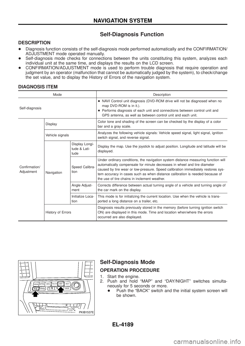
1. Start the engine.
2. Push and hold ªMAPº and ªDAY/NIGHTº switches simulta-
neously for 5 seconds or more.
+ Push the ªBACKº switch and the initial system screen will
be shown.
PKIB1537E
NAVIGATION SYSTEM
EL-4189
Page 290 of 579
Angle adjustment
+Adjust turning angle output detected by the gyroscope.
Initialize location
Description
+Location data for GPS in the Center control unit is initialized in
Europe by this mode. Then it is possible for Center control unit
to receive GPS signals for short time.
How to perform ªInitialize Locationº mode
1. Select ªInitialize Locationº, and push ªENTERº.
2. A message ªPlease wait.º is displayed and then backs to another display of ªCon®rmation/Adjustmentº mode.
NOTE:
+ To continue GPS initialized operation, operate as follows back
to ªMapº screen.
Ð Push ªBACKº button twice.
Ð Push ªMAPº button.
+ After above operation, GPS indicator changes to green color
within half a minute, unless improper GPS located condition.
+ This operation should be performed in out side ®eld.
HISTORY OF ERRORS
SKIA0364E
SKIA1618E
SKIA1619E
SKIA9553E
NAVIGATION SYSTEM
Con®rmation/Adjustment Mode (Cont'd)
EL-4195
Page 301 of 579

2. CHECK HARNESS
1. Turn ignition switch OFF.
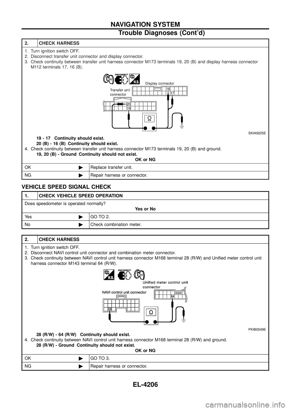
2. Disconnect transfer unit connector and display connector.
3. Check continuity between transfer unit harness connector M173 terminals 19, 20 (B) and display harness connectorM112 terminals 17, 16 (B).
SKIA9225E
19 - 17 Continuity should exist.
20 (B) - 16 (B) Continuity should exist.
4. Check continuity between transfer unit harness connector M173 terminals 19, 20 (B) and ground. 19, 20 (B) - Ground Continuity should not exist. OK or NG
OK ©Replace transfer unit.
NG ©Repair harness or connector.
VEHICLE SPEED SIGNAL CHECK
1. CHECK VEHICLE SPEED OPERATION
Does speedometer is operated normally?
YesorNo
Ye s ©GO TO 2.
No ©Check combination meter.
2. CHECK HARNESS
1. Turn ignition switch OFF.
2. Disconnect NAVI control unit connector and combination meter connector.
3. Check continuity between NAVI control unit harness connector M168 terminal 28 (R/W) and Uni®ed meter control unit
harness connector M143 terminal 64 (R/W).
PKIB0549E
28 (R/W) - 64 (R/W) Continuity should exist.
4. Check continuity between NAVI control unit harness connector M168 terminal 28 (R/W) and ground. 28 (R/W) - Ground Continuity should not exist. OK or NG
OK ©GO TO 3.
NG ©Repair harness or connector.
NAVIGATION SYSTEM
Trouble Diagnoses (Cont'd)
EL-4206