2004 NISSAN PATROL relay
[x] Cancel search: relayPage 46 of 579
jB
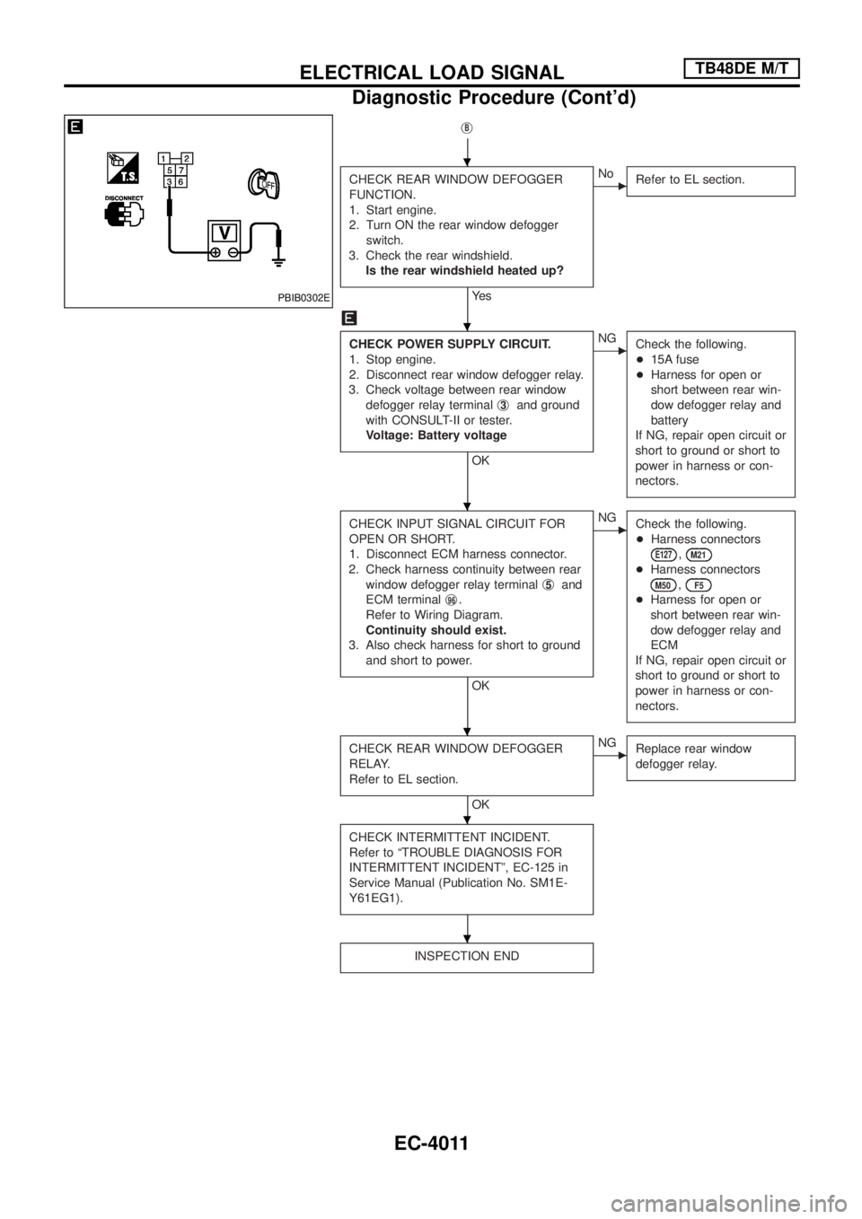
CHECK REAR WINDOW DEFOGGER
FUNCTION.
1. Start engine.
2. Turn ON the rear window defogger
switch.
3. Check the rear windshield.
Is the rear windshield heated up?
Ye s
cNo
Refer to EL section.
CHECK POWER SUPPLY CIRCUIT.
1. Stop engine.
2. Disconnect rear window defogger relay.
3. Check voltage between rear window
defogger relay terminalj
3and ground
with CONSULT-II or tester.
Voltage: Battery voltage
OK
cNG
Check the following.
+15A fuse
+Harness for open or
short between rear win-
dow defogger relay and
battery
If NG, repair open circuit or
short to ground or short to
power in harness or con-
nectors.
CHECK INPUT SIGNAL CIRCUIT FOR
OPEN OR SHORT.
1. Disconnect ECM harness connector.
2. Check harness continuity between rear
window defogger relay terminalj
5and
ECM terminalj
96.
Refer to Wiring Diagram.
Continuity should exist.
3. Also check harness for short to ground
and short to power.
OK
cNG
Check the following.
+Harness connectors
E127,M21
+Harness connectors
M50,F5
+Harness for open or
short between rear win-
dow defogger relay and
ECM
If NG, repair open circuit or
short to ground or short to
power in harness or con-
nectors.
CHECK REAR WINDOW DEFOGGER
RELAY.
Refer to EL section.
OK
cNG
Replace rear window
defogger relay.
CHECK INTERMITTENT INCIDENT.
Refer to ªTROUBLE DIAGNOSIS FOR
INTERMITTENT INCIDENTº, EC-125 in
Service Manual (Publication No. SM1E-
Y61EG1).
INSPECTION END
PBIB0302E
.
.
.
.
.
.
ELECTRICAL LOAD SIGNALTB48DE M/T
Diagnostic Procedure (Cont'd)
EC-4011
Page 54 of 579
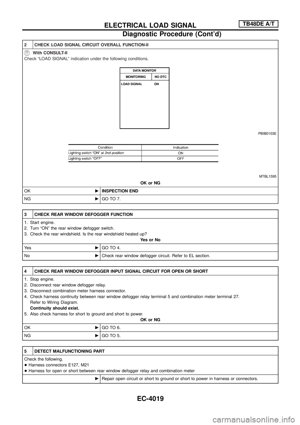
2 CHECK LOAD SIGNAL CIRCUIT OVERALL FUNCTION-II
With CONSULT-II
Check ªLOAD SIGNALº indication under the following conditions.
PBIB0103E
MTBL1595
OK or NG
OKcINSPECTION END
NGcGO TO 7.
3 CHECK REAR WINDOW DEFOGGER FUNCTION
1. Start engine.
2. Turn ªONº the rear window defogger switch.
3. Check the rear windshield. Is the rear windshield heated up?
YesorNo
Ye scGO TO 4.
NocCheck rear window defogger circuit. Refer to EL section.
4 CHECK REAR WINDOW DEFOGGER INPUT SIGNAL CIRCUIT FOR OPEN OR SHORT
1. Stop engine.
2. Disconnect rear window defogger relay.
3. Disconnect combination meter harness connector.
4. Check harness continuity between rear window defogger relay terminal 5 and combination meter terminal 27.
Refer to Wiring Diagram.
Continuity should exist.
5. Also check harness for short to ground and short to power.
OK or NG
OKcGO TO 6.
NGcGO TO 5.
5 DETECT MALFUNCTIONING PART
Check the following.
+Harness connectors E127, M21
+Harness for open or short between rear window defogger relay and combination meter
cRepair open circuit or short to ground or short to power in harness or connectors.
ELECTRICAL LOAD SIGNALTB48DE A/T
Diagnostic Procedure (Cont'd)
EC-4019
Page 63 of 579
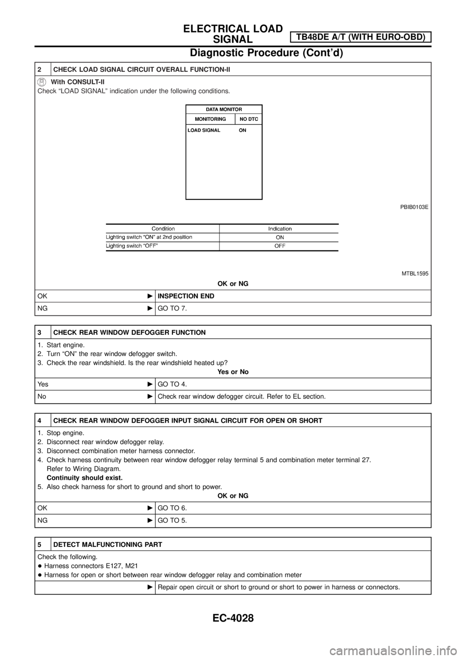
2 CHECK LOAD SIGNAL CIRCUIT OVERALL FUNCTION-II
With CONSULT-II
Check ªLOAD SIGNALº indication under the following conditions.
PBIB0103E
MTBL1595
OK or NG
OKcINSPECTION END
NGcGO TO 7.
3 CHECK REAR WINDOW DEFOGGER FUNCTION
1. Start engine.
2. Turn ªONº the rear window defogger switch.
3. Check the rear windshield. Is the rear windshield heated up?
YesorNo
Ye scGO TO 4.
NocCheck rear window defogger circuit. Refer to EL section.
4 CHECK REAR WINDOW DEFOGGER INPUT SIGNAL CIRCUIT FOR OPEN OR SHORT
1. Stop engine.
2. Disconnect rear window defogger relay.
3. Disconnect combination meter harness connector.
4. Check harness continuity between rear window defogger relay terminal 5 and combination meter terminal 27.
Refer to Wiring Diagram.
Continuity should exist.
5. Also check harness for short to ground and short to power.
OK or NG
OKcGO TO 6.
NGcGO TO 5.
5 DETECT MALFUNCTIONING PART
Check the following.
+Harness connectors E127, M21
+Harness for open or short between rear window defogger relay and combination meter
cRepair open circuit or short to ground or short to power in harness or connectors.
ELECTRICAL LOAD
SIGNALTB48DE A/T (WITH EURO-OBD)
Diagnostic Procedure (Cont'd)
EC-4028
Page 75 of 579
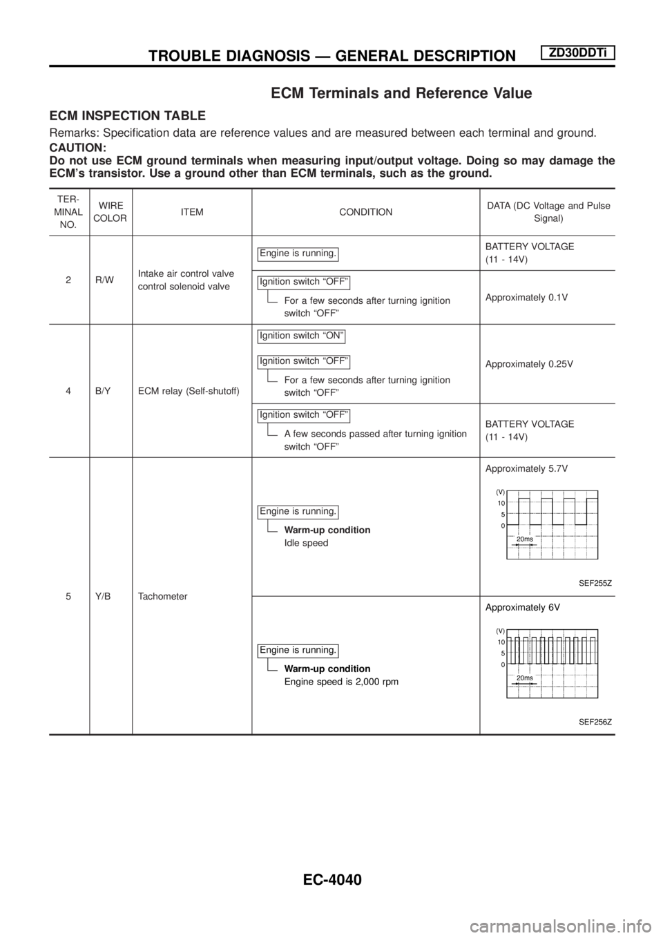
ECM Terminals and Reference Value
ECM INSPECTION TABLE
Remarks: Speci®cation data are reference values and are measured between each terminal and ground.
CAUTION:
Do not use ECM ground terminals when measuring input/output voltage. Doing so may damage the
ECM's transistor. Use a ground other than ECM terminals, such as the ground.
TER-
MINAL
NO.WIRE
COLORITEM CONDITIONDATA (DC Voltage and Pulse
Signal)
2 R/WIntake air control valve
control solenoid valveEngine is running.
BATTERY VOLTAGE
(11 - 14V)
Ignition switch ªOFFº
For a few seconds after turning ignition
switch ªOFFºApproximately 0.1V
4 B/Y ECM relay (Self-shutoff)Ignition switch ªONº
Ignition switch ªOFFº
For a few seconds after turning ignition
switch ªOFFºApproximately 0.25V
Ignition switch ªOFFº
A few seconds passed after turning ignition
switch ªOFFºBATTERY VOLTAGE
(11 - 14V)
5 Y/B TachometerEngine is running.
Warm-up condition
Idle speedApproximately 5.7V
SEF255Z
Engine is running.
Warm-up condition
Engine speed is 2,000 rpmApproximately 6V
SEF256Z
TROUBLE DIAGNOSIS Ð GENERAL DESCRIPTIONZD30DDTi
EC-4040
Page 76 of 579
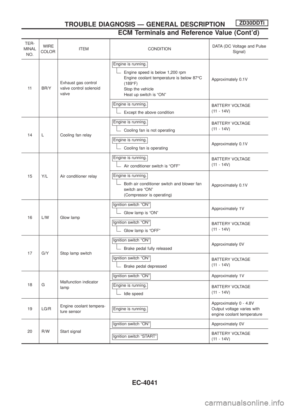
TER-
MINAL
NO.WIRE
COLORITEM CONDITIONDATA (DC Voltage and Pulse
Signal)
11 BR/YExhaust gas control
valve control solenoid
valveEngine is running.
Engine speed is below 1,200 rpm
Engine coolant temperature is below 87ÉC
(189ÉF)
Stop the vehicle
Heat up switch is ªONºApproximately 0.1V
Engine is running.
Except the above conditionBATTERY VOLTAGE
(11 - 14V)
14 L Cooling fan relayEngine is running.
Cooling fan is not operatingBATTERY VOLTAGE
(11 - 14V)
Engine is running.
Cooling fan is operatingApproximately 0.1V
15 Y/L Air conditioner relayEngine is running.
Air conditioner switch is ªOFFºBATTERY VOLTAGE
(11 - 14V)
Engine is running.
Both air conditioner switch and blower fan
switch are ªONº
(Compressor is operating)Approximately 0.1V
16 L/W Glow lampIgnition switch ªONº
Glow lamp is ªONºApproximately 1V
Ignition switch ªONº
Glow lamp is ªOFFºBATTERY VOLTAGE
(11 - 14V)
17 G/Y Stop lamp switchIgnition switch ªONº
Brake pedal fully releasedApproximately 0V
Ignition switch ªONº
Brake pedal depressedBATTERY VOLTAGE
(11 - 14V)
18 GMalfunction indicator
lampIgnition switch ªONº
Approximately 1V
Engine is running.
Idle speedBATTERY VOLTAGE
(11 - 14V)
19 LG/REngine coolant tempera-
ture sensorEngine is running.
Approximately 0 - 4.8V
Output voltage varies with
engine coolant temperature
20 R/W Start signalIgnition switch ªONº
Approximately 0V
Ignition switch ªSTARTº
BATTERY VOLTAGE
(11 - 14V)
TROUBLE DIAGNOSIS Ð GENERAL DESCRIPTIONZD30DDTi
ECM Terminals and Reference Value (Cont'd)
EC-4041
Page 81 of 579
TER-
MINAL
NO.WIRE
COLORITEM CONDITIONDATA (DC Voltage and Pulse
Signal)
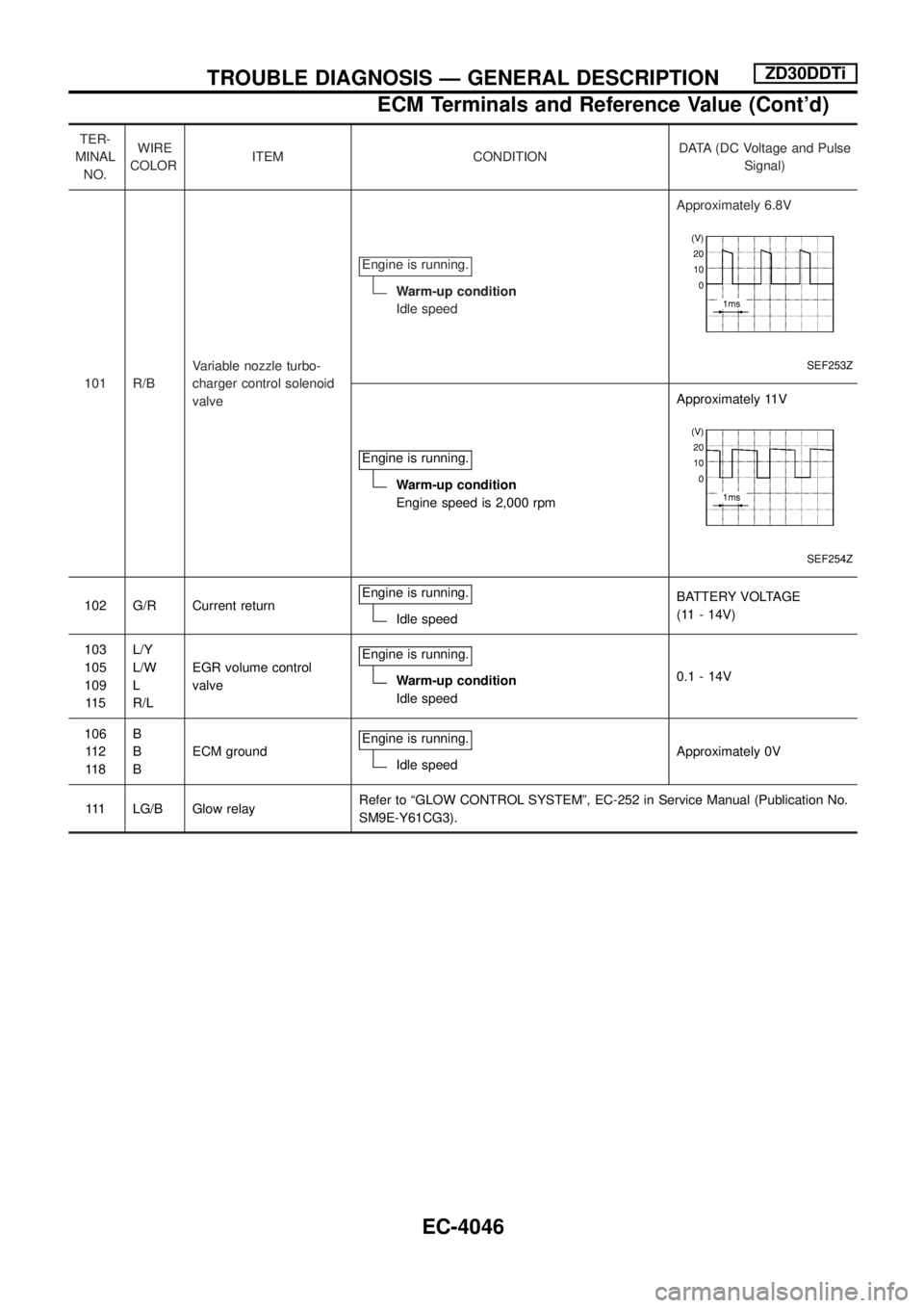
101 R/BVariable nozzle turbo-
charger control solenoid
valveEngine is running.
Warm-up condition
Idle speedApproximately 6.8V
SEF253Z
Engine is running.
Warm-up condition
Engine speed is 2,000 rpmApproximately 11V
SEF254Z
102 G/R Current returnEngine is running.Idle speedBATTERY VOLTAGE
(11 - 14V)
103
105
109
11 5L/Y
L/W
L
R/LEGR volume control
valveEngine is running.
Warm-up condition
Idle speed0.1 - 14V
106
11 2
11 8B
B
BECM groundEngine is running.
Idle speedApproximately 0V
111 LG/B Glow relayRefer to ªGLOW CONTROL SYSTEMº, EC-252 in Service Manual (Publication No.
SM9E-Y61CG3).
TROUBLE DIAGNOSIS Ð GENERAL DESCRIPTIONZD30DDTi
ECM Terminals and Reference Value (Cont'd)
EC-4046
Page 85 of 579
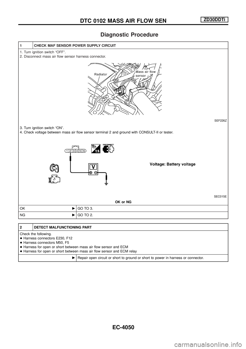
Diagnostic Procedure
1 CHECK MAF SENSOR POWER SUPPLY CIRCUIT
1. Turn ignition switch ªOFFº.
2. Disconnect mass air ¯ow sensor harness connector.
SEF226Z
3. Turn ignition switch ªONº.
4. Check voltage between mass air ¯ow sensor terminal 2 and ground with CONSULT-II or tester.
SEC015E
OK or NG
OKcGO TO 3.
NGcGO TO 2.
2 DETECT MALFUNCTIONING PART
Check the following.
+Harness connectors E230, F12
+Harness connectors M50, F5
+Harness for open or short between mass air ¯ow sensor and ECM
+Harness for open or short between mass air ¯ow sensor and ECM relay
cRepair open circuit or short to ground or short to power in harness or connector.
DTC 0102 MASS AIR FLOW SENZD30DDTi
EC-4050
Page 98 of 579
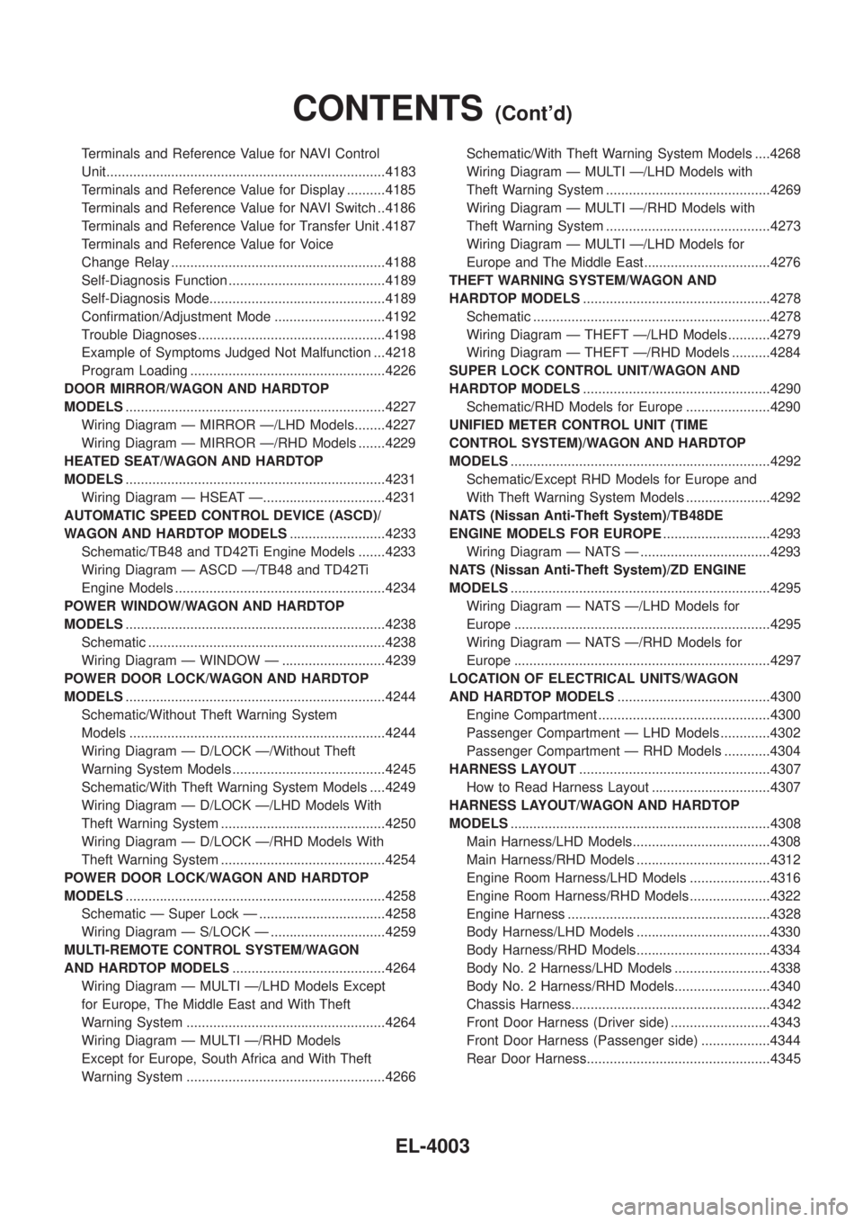
Terminals and Reference Value for NAVI Control
Unit........................................................................\
.4183
Terminals and Reference Value for Display ..........4185
Terminals and Reference Value for NAVI Switch ..4186
Terminals and Reference Value for Transfer Unit .4187
Terminals and Reference Value for Voice
Change Relay ........................................................4188
Self-Diagnosis Function .........................................4189
Self-Diagnosis Mode..............................................4189
Con®rmation/Adjustment Mode .............................4192
Trouble Diagnoses.................................................4198
Example of Symptoms Judged Not Malfunction ...4218
Program Loading ...................................................4226
DOOR MIRROR/WAGON AND HARDTOP
MODELS ....................................................................4227
Wiring Diagram Ð MIRROR Ð/LHD Models........4227
Wiring Diagram Ð MIRROR Ð/RHD Models .......4229
HEATED SEAT/WAGON AND HARDTOP
MODELS ....................................................................4231
Wiring Diagram Ð HSEAT Ð................................4231
AUTOMATIC SPEED CONTROL DEVICE (ASCD)/
WAGON AND HARDTOP MODELS .........................4233
Schematic/TB48 and TD42Ti Engine Models .......4233
Wiring Diagram Ð ASCD Ð/TB48 and TD42Ti
Engine Models .......................................................4234
POWER WINDOW/WAGON AND HARDTOP
MODELS ....................................................................4238
Schematic ..............................................................4238
Wiring Diagram Ð WINDOW Ð ...........................4239
POWER DOOR LOCK/WAGON AND HARDTOP
MODELS ....................................................................4244
Schematic/Without Theft Warning System
Models ...................................................................4244
Wiring Diagram Ð D/LOCK Ð/Without Theft
Warning System Models ........................................4245
Schematic/With Theft Warning System Models ....4249
Wiring Diagram Ð D/LOCK Ð/LHD Models With
Theft Warning System ...........................................4250
Wiring Diagram Ð D/LOCK Ð/RHD Models With
Theft Warning System ...........................................4254
POWER DOOR LOCK/WAGON AND HARDTOP
MODELS ....................................................................4258
Schematic Ð Super Lock Ð .................................4258
Wiring Diagram Ð S/LOCK Ð ..............................4259
MULTI-REMOTE CONTROL SYSTEM/WAGON
AND HARDTOP MODELS ........................................4264
Wiring Diagram Ð MULTI Ð/LHD Models Except
for Europe, The Middle East and With Theft
Warning System ....................................................4264
Wiring Diagram Ð MULTI Ð/RHD Models
Except for Europe, South Africa and With Theft
Warning System ....................................................4266 Schematic/With Theft Warning System Models ....4268
Wiring Diagram Ð MULTI Ð/LHD Models with
Theft Warning System ...........................................4269
Wiring Diagram Ð MULTI Ð/RHD Models with
Theft Warning System ...........................................4273
Wiring Diagram Ð MULTI Ð/LHD Models for
Europe and The Middle East.................................4276
THEFT WARNING SYSTEM/WAGON AND
HARDTOP MODELS .................................................4278
Schematic ..............................................................4278
Wiring Diagram Ð THEFT Ð/LHD Models ...........4279
Wiring Diagram Ð THEFT Ð/RHD Models ..........4284
SUPER LOCK CONTROL UNIT/WAGON AND
HARDTOP MODELS .................................................4290
Schematic/RHD Models for Europe ......................4290
UNIFIED METER CONTROL UNIT (TIME
CONTROL SYSTEM)/WAGON AND HARDTOP
MODELS ....................................................................4292
Schematic/Except RHD Models for Europe and
With Theft Warning System Models ......................4292
NATS (Nissan Anti-Theft System)/TB48DE
ENGINE MODELS FOR EUROPE ............................4293
Wiring Diagram Ð NATS Ð ..................................4293
NATS (Nissan Anti-Theft System)/ZD ENGINE
MODELS ....................................................................4295
Wiring Diagram Ð NATS Ð/LHD Models for
Europe ...................................................................4295
Wiring Diagram Ð NATS Ð/RHD Models for
Europe ...................................................................4297
LOCATION OF ELECTRICAL UNITS/WAGON
AND HARDTOP MODELS ........................................4300
Engine Compartment .............................................4300
Passenger Compartment Ð LHD Models .............4302
Passenger Compartment Ð RHD Models ............4304
HARNESS LAYOUT ..................................................4307
How to Read Harness Layout ...............................4307
HARNESS LAYOUT/WAGON AND HARDTOP
MODELS ....................................................................4308
Main Harness/LHD Models....................................4308
Main Harness/RHD Models ...................................4312
Engine Room Harness/LHD Models .....................4316
Engine Room Harness/RHD Models .....................4322
Engine Harness .....................................................4328
Body Harness/LHD Models ...................................4330
Body Harness/RHD Models...................................4334
Body No. 2 Harness/LHD Models .........................4338
Body No. 2 Harness/RHD Models.........................4340
Chassis Harness....................................................4342
Front Door Harness (Driver side) ..........................4343
Front Door Harness (Passenger side) ..................4344
Rear Door Harness................................................4345
CONTENTS(Cont'd)
EL-4003