2004 NISSAN PATROL Switch
[x] Cancel search: SwitchPage 26 of 579
CAUTION:
+Disconnect both battery cables in advance.
+Disconnect air bag system line in advance.
+Never tamper with or force air bag lid open, as this may adversely affect air bag performance.
+Be careful not to scratch pad and other parts.
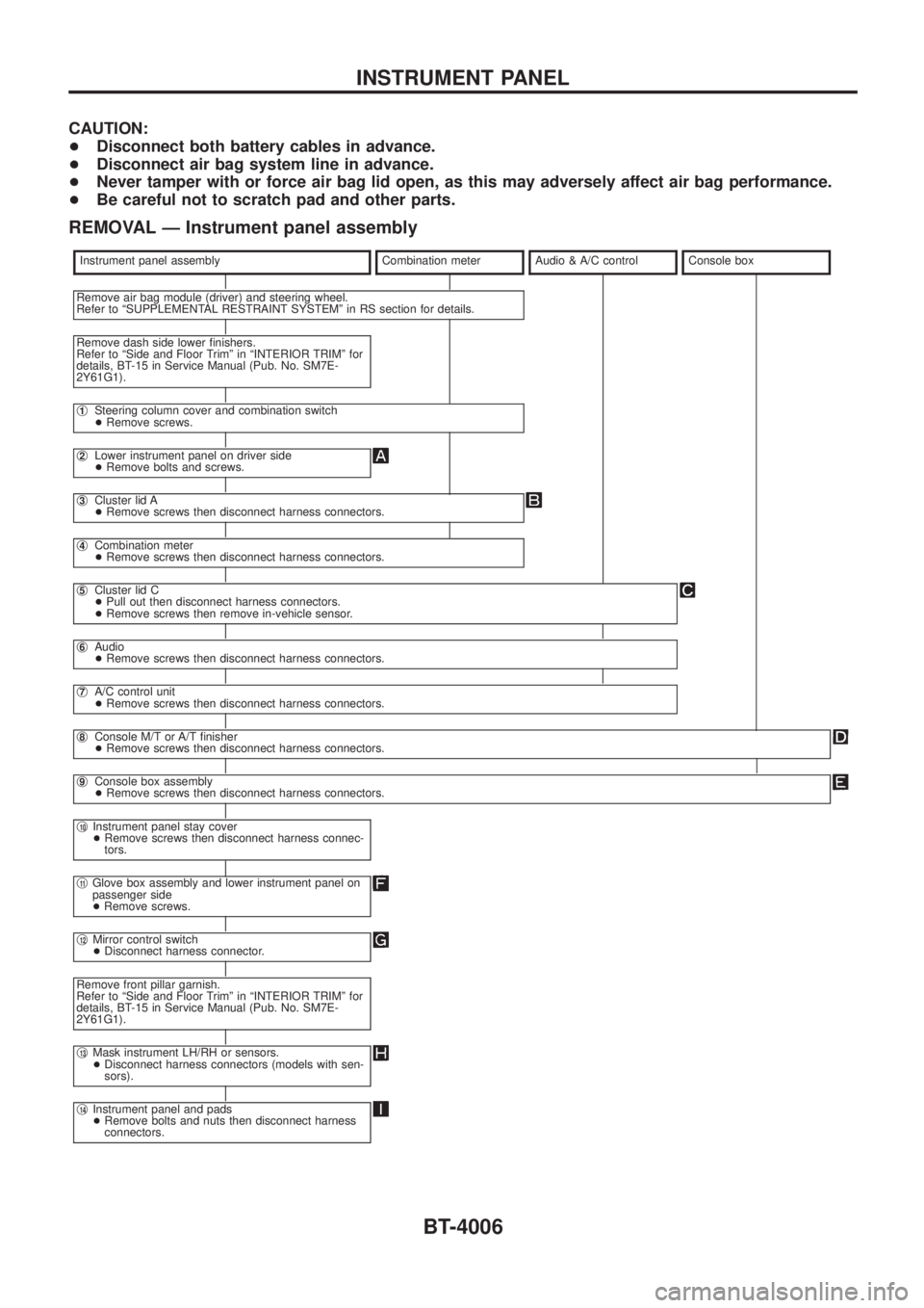
REMOVAL Ð Instrument panel assembly
Instrument panel assemblyCombination meterAudio & A/C controlConsole box
Remove air bag module (driver) and steering wheel.
Refer to ªSUPPLEMENTAL RESTRAINT SYSTEMº in RS section for details.
Remove dash side lower ®nishers.
Refer to ªSide and Floor Trimº in ªINTERIOR TRIMº for
details, BT-15 in Service Manual (Pub. No. SM7E-
2Y61G1).
j1Steering column cover and combination switch
+Remove screws.
j2Lower instrument panel on driver side
+Remove bolts and screws.
j3Cluster lid A
+Remove screws then disconnect harness connectors.
j4Combination meter
+Remove screws then disconnect harness connectors.
j5Cluster lid C
+Pull out then disconnect harness connectors.
+Remove screws then remove in-vehicle sensor.
j6Audio
+Remove screws then disconnect harness connectors.
j7A/C control unit
+Remove screws then disconnect harness connectors.
j8Console M/T or A/T ®nisher
+Remove screws then disconnect harness connectors.
j9Console box assembly
+Remove screws then disconnect harness connectors.
j10Instrument panel stay cover
+Remove screws then disconnect harness connec-
tors.
j11Glove box assembly and lower instrument panel on
passenger side
+Remove screws.
j12Mirror control switch
+Disconnect harness connector.
Remove front pillar garnish.
Refer to ªSide and Floor Trimº in ªINTERIOR TRIMº for
details, BT-15 in Service Manual (Pub. No. SM7E-
2Y61G1).
j13Mask instrument LH/RH or sensors.
+Disconnect harness connectors (models with sen-
sors).
j14Instrument panel and pads
+Remove bolts and nuts then disconnect harness
connectors.
INSTRUMENT PANEL
BT-4006
Page 36 of 579
SECTION
EC
MODIFICATION NOTICE:
+Wiring diagrams have been modi®ed.
+ MAF sensor has been changed for ZD30DDTi engine models.
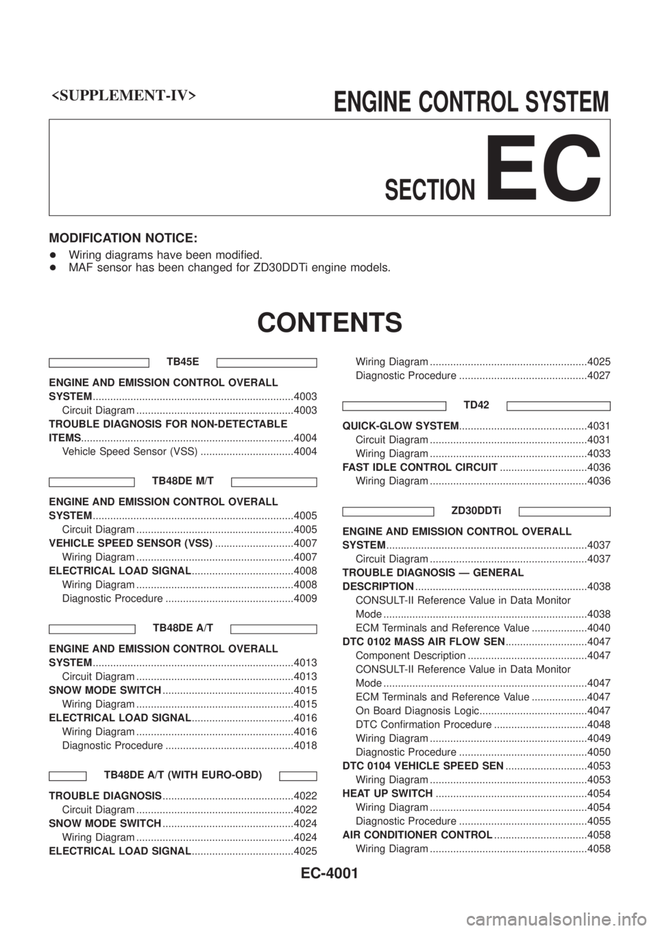
CONTENTS
TB45E
ENGINE AND EMISSION CONTROL OVERALL
SYSTEM .....................................................................4003
Circuit Diagram ......................................................4003
TROUBLE DIAGNOSIS FOR NON-DETECTABLE
ITEMS ........................................................................\
.4004
Vehicle Speed Sensor (VSS) ................................4004
TB48DE M/T
ENGINE AND EMISSION CONTROL OVERALL
SYSTEM.....................................................................4005
Circuit Diagram ......................................................4005
VEHICLE SPEED SENSOR (VSS) ...........................4007
Wiring Diagram ......................................................4007
ELECTRICAL LOAD SIGNAL ...................................4008
Wiring Diagram ......................................................4008
Diagnostic Procedure ............................................4009
TB48DE A/T
ENGINE AND EMISSION CONTROL OVERALL
SYSTEM.....................................................................4013
Circuit Diagram ......................................................4013
SNOW MODE SWITCH .............................................4015
Wiring Diagram ......................................................4015
ELECTRICAL LOAD SIGNAL ...................................4016
Wiring Diagram ......................................................4016
Diagnostic Procedure ............................................4018
TB48DE A/T (WITH EURO-OBD)
TROUBLE DIAGNOSIS .............................................4022
Circuit Diagram ......................................................4022
SNOW MODE SWITCH .............................................4024
Wiring Diagram ......................................................4024
ELECTRICAL LOAD SIGNAL ...................................4025 Wiring Diagram ......................................................4025
Diagnostic Procedure ............................................4027
TD42
QUICK-GLOW SYSTEM ............................................4031
Circuit Diagram ......................................................4031
Wiring Diagram ......................................................4033
FAST IDLE CONTROL CIRCUIT ..............................4036
Wiring Diagram ......................................................4036
ZD30DDTi
ENGINE AND EMISSION CONTROL OVERALL
SYSTEM.....................................................................4037
Circuit Diagram ......................................................4037
TROUBLE DIAGNOSIS Ð GENERAL
DESCRIPTION ...........................................................4038
CONSULT-II Reference Value in Data Monitor
Mode ......................................................................4038
ECM Terminals and Reference Value ...................4040
DTC 0102 MASS AIR FLOW SEN ............................4047
Component Description .........................................4047
CONSULT-II Reference Value in Data Monitor
Mode ......................................................................4047
ECM Terminals and Reference Value ...................4047
On Board Diagnosis Logic.....................................4047
DTC Con®rmation Procedure ................................4048
Wiring Diagram ......................................................4049
Diagnostic Procedure ............................................4050
DTC 0104 VEHICLE SPEED SEN ............................4053
Wiring Diagram ......................................................4053
HEAT UP SWITCH ....................................................4054
Wiring Diagram ......................................................4054
Diagnostic Procedure ............................................4055
AIR CONDITIONER CONTROL ................................4058
Wiring Diagram ......................................................4058
EC-4001
Page 44 of 579
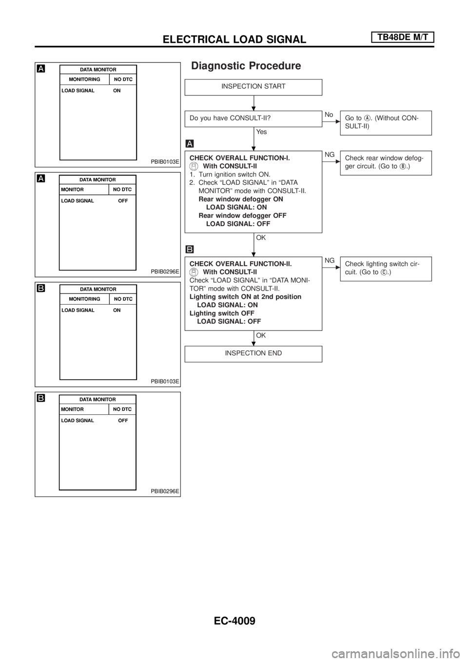
Diagnostic Procedure
INSPECTION START
Do you have CONSULT-II?
Ye s
cNo
Go tojA. (Without CON-
SULT-II)
CHECK OVERALL FUNCTION-I.
With CONSULT-II
1. Turn ignition switch ON.
2. Check ªLOAD SIGNALº in ªDATA
MONITORº mode with CONSULT-II.
Rear window defogger ON
LOAD SIGNAL: ON
Rear window defogger OFF
LOAD SIGNAL: OFF
OK
cNG
Check rear window defog-
ger circuit. (Go toj
B.)
CHECK OVERALL FUNCTION-II.
With CONSULT-II
Check ªLOAD SIGNALº in ªDATA MONI-
TORº mode with CONSULT-II.
Lighting switch ON at 2nd position
LOAD SIGNAL: ON
Lighting switch OFF
LOAD SIGNAL: OFF
OK
cNG
Check lighting switch cir-
cuit. (Go toj
C.)
INSPECTION END
PBIB0103E
PBIB0296E
PBIB0103E
PBIB0296E
.
.
.
.
ELECTRICAL LOAD SIGNALTB48DE M/T
EC-4009
Page 45 of 579
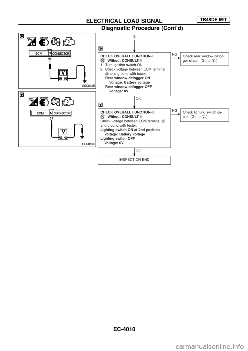
jA
CHECK OVERALL FUNCTION-I.
Without CONSULT-II
1. Turn ignition switch ON.
2. Check voltage between ECM terminal
j
96and ground with tester.
Rear window defogger ON
Voltage: Battery voltage
Rear window defogger OFF
Voltage: 0V
OK
cNG
Check rear window defog-
ger circuit. (Go toj
B.)
CHECK OVERALL FUNCTION-II.
Without CONSULT-II
Check voltage between ECM terminalj
97
and ground with tester.
Lighting switch ON at 2nd position
Voltage: Battery voltage
Lighting switch OFF
Voltage: 0V
OK
cNG
Check lighting switch cir-
cuit. (Go toj
C.)
INSPECTION END
SEC022E
SEC010E
.
.
.
ELECTRICAL LOAD SIGNALTB48DE M/T
Diagnostic Procedure (Cont'd)
EC-4010
Page 46 of 579
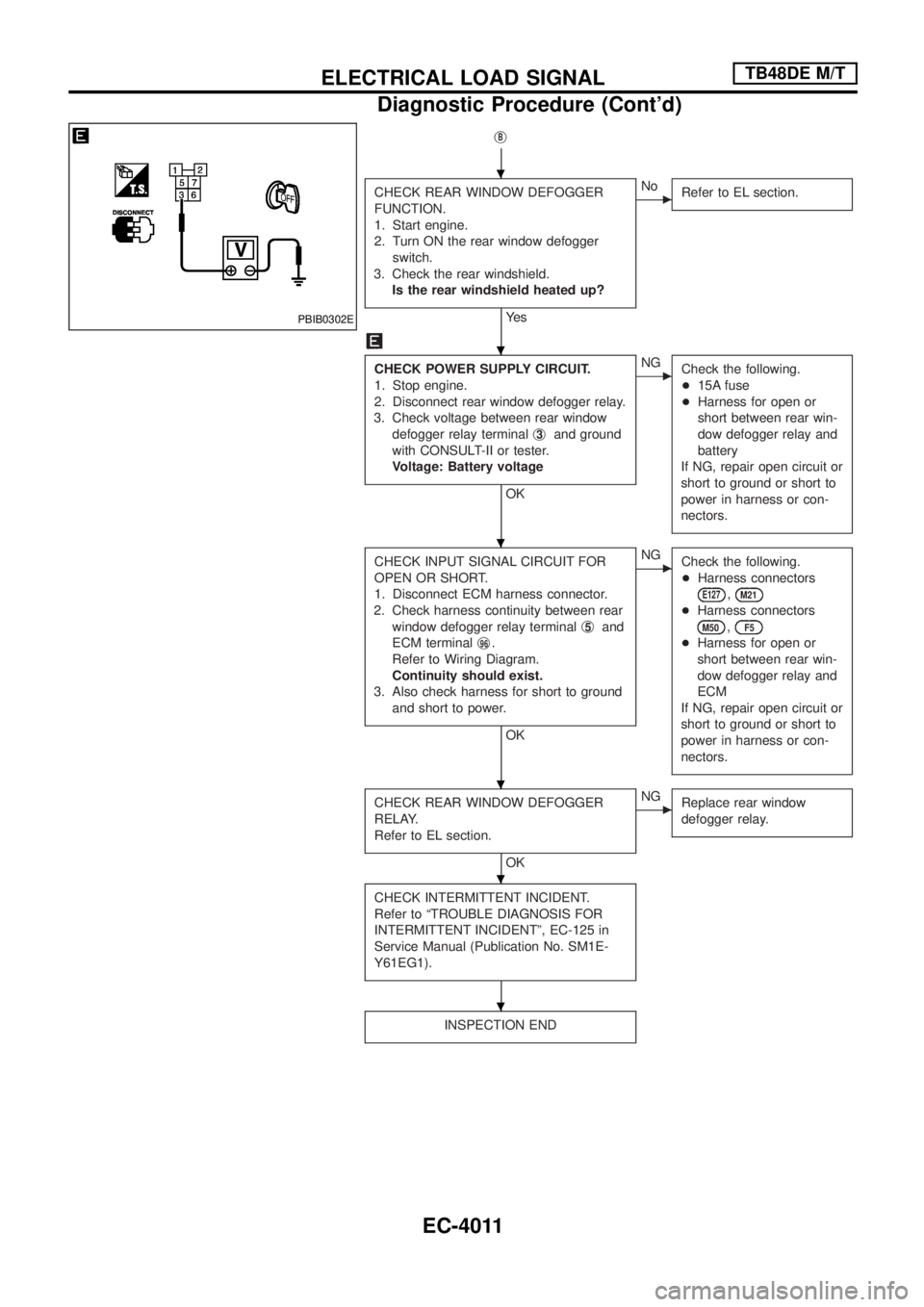
jB
CHECK REAR WINDOW DEFOGGER
FUNCTION.
1. Start engine.
2. Turn ON the rear window defogger
switch.
3. Check the rear windshield.
Is the rear windshield heated up?
Ye s
cNo
Refer to EL section.
CHECK POWER SUPPLY CIRCUIT.
1. Stop engine.
2. Disconnect rear window defogger relay.
3. Check voltage between rear window
defogger relay terminalj
3and ground
with CONSULT-II or tester.
Voltage: Battery voltage
OK
cNG
Check the following.
+15A fuse
+Harness for open or
short between rear win-
dow defogger relay and
battery
If NG, repair open circuit or
short to ground or short to
power in harness or con-
nectors.
CHECK INPUT SIGNAL CIRCUIT FOR
OPEN OR SHORT.
1. Disconnect ECM harness connector.
2. Check harness continuity between rear
window defogger relay terminalj
5and
ECM terminalj
96.
Refer to Wiring Diagram.
Continuity should exist.
3. Also check harness for short to ground
and short to power.
OK
cNG
Check the following.
+Harness connectors
E127,M21
+Harness connectors
M50,F5
+Harness for open or
short between rear win-
dow defogger relay and
ECM
If NG, repair open circuit or
short to ground or short to
power in harness or con-
nectors.
CHECK REAR WINDOW DEFOGGER
RELAY.
Refer to EL section.
OK
cNG
Replace rear window
defogger relay.
CHECK INTERMITTENT INCIDENT.
Refer to ªTROUBLE DIAGNOSIS FOR
INTERMITTENT INCIDENTº, EC-125 in
Service Manual (Publication No. SM1E-
Y61EG1).
INSPECTION END
PBIB0302E
.
.
.
.
.
.
ELECTRICAL LOAD SIGNALTB48DE M/T
Diagnostic Procedure (Cont'd)
EC-4011
Page 47 of 579
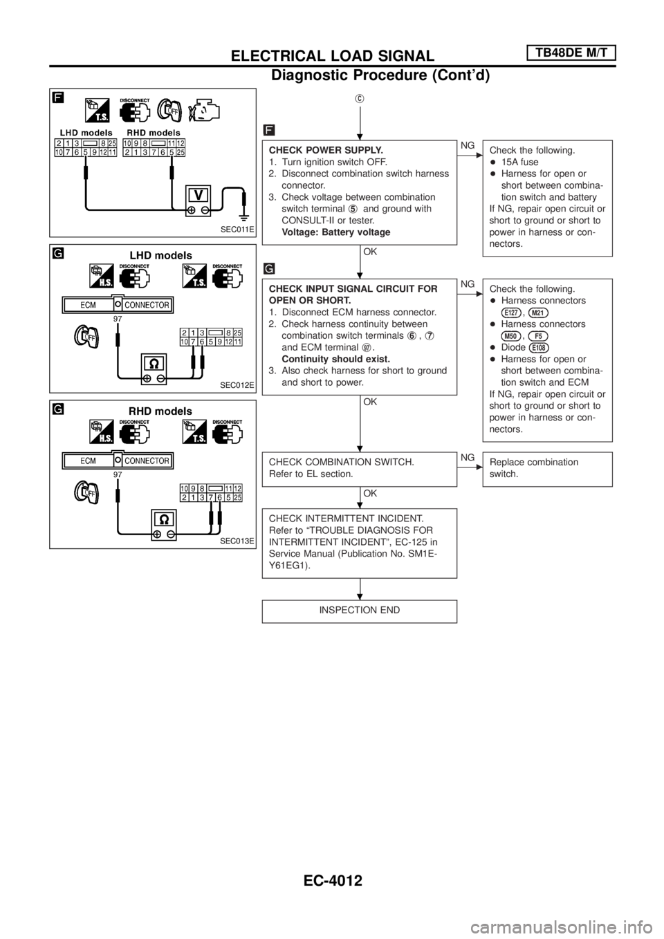
jC
CHECK POWER SUPPLY.
1. Turn ignition switch OFF.
2. Disconnect combination switch harness
connector.
3. Check voltage between combination
switch terminalj
5and ground with
CONSULT-II or tester.
Voltage: Battery voltage
OK
cNG
Check the following.
+15A fuse
+Harness for open or
short between combina-
tion switch and battery
If NG, repair open circuit or
short to ground or short to
power in harness or con-
nectors.
CHECK INPUT SIGNAL CIRCUIT FOR
OPEN OR SHORT.
1. Disconnect ECM harness connector.
2. Check harness continuity between
combination switch terminalsj
6,j7
and ECM terminalj97.
Continuity should exist.
3. Also check harness for short to ground
and short to power.
OK
cNG
Check the following.
+Harness connectors
E127,M21
+Harness connectors
M50,F5
+DiodeE108
+Harness for open or
short between combina-
tion switch and ECM
If NG, repair open circuit or
short to ground or short to
power in harness or con-
nectors.
CHECK COMBINATION SWITCH.
Refer to EL section.
OK
cNG
Replace combination
switch.
CHECK INTERMITTENT INCIDENT.
Refer to ªTROUBLE DIAGNOSIS FOR
INTERMITTENT INCIDENTº, EC-125 in
Service Manual (Publication No. SM1E-
Y61EG1).
INSPECTION END
SEC011E
SEC012E
SEC013E
.
.
.
.
.
ELECTRICAL LOAD SIGNALTB48DE M/T
Diagnostic Procedure (Cont'd)
EC-4012
Page 50 of 579

Wiring Diagram
WITH SNOW MODE SWITCH
TEC521M
SNOW MODE SWITCHTB48DE A/T
EC-4015
Page 53 of 579
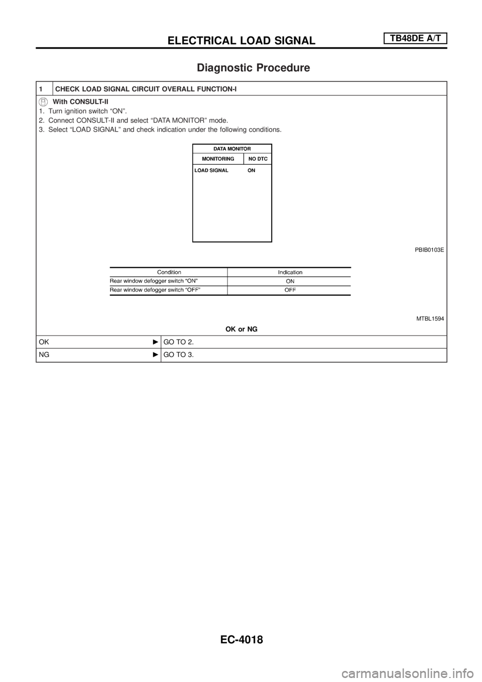
Diagnostic Procedure
1 CHECK LOAD SIGNAL CIRCUIT OVERALL FUNCTION-I
With CONSULT-II
1. Turn ignition switch ªONº.
2. Connect CONSULT-II and select ªDATA MONITORº mode.
3. Select ªLOAD SIGNALº and check indication under the following conditions.
PBIB0103E
MTBL1594
OK or NG
OKcGO TO 2.
NGcGO TO 3.
ELECTRICAL LOAD SIGNALTB48DE A/T
EC-4018