2004 NISSAN PATROL ECO mode
[x] Cancel search: ECO modePage 2 of 579
FOREWORD
This manual contains maintenance and repair procedures for NISSAN
PATROL,modelY61 series.
In order to assure your safety and the efficient functioning of the vehicle,
this manual should be read thoroughly. It is especially important that the
PRECAUTIONS in the GI section be completely understood before starting
any repair task.
All information in this manual is based on the latest product information
at the time of publication. The right is reserved to make changes in speci-
®cations and methods at any time without notice.
IMPORTANT SAFETY NOTICE
The proper performance of service is essential for both the safety of the
technician and the efficient functioning of the vehicle.
The service methods in this Service Manual are described in such a man-
ner that the service may be performed safely and accurately.
Service varies with the procedures used, the skills of the technician and the
tools and parts available. Accordingly, anyone using service procedures,
tools or parts which are not speci®cally recommended by NISSAN must
®rst completely satisfy himself that neither his safety nor the vehicle's
safety will be jeopardized by the service method selected.
NISSAN EUROPE S.A.S.
Service Engineering SectionParis, France
Page 16 of 579
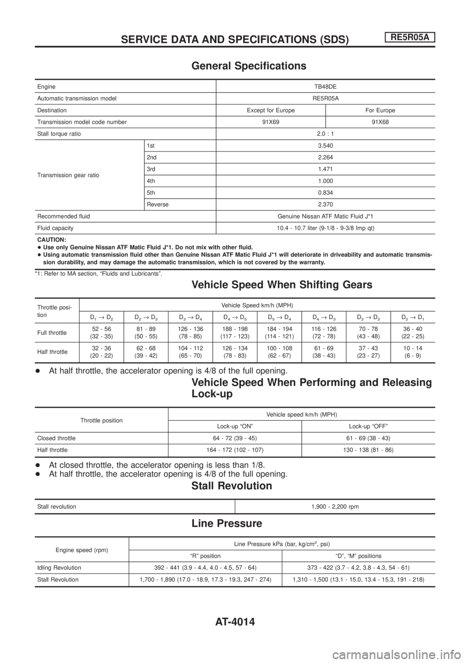
General Speci®cations
EngineTB48DE
Automatic transmission modelRE5R05A
Destination Except for Europe For Europe
Transmission model code number 91X69 91X68
Stall torque ratio2.0:1
Transmission gear ratio1st 3.540
2nd 2.264
3rd 1.471
4th 1.000
5th 0.834
Reverse 2.370
Recommended ¯uid Genuine Nissan ATF Matic Fluid J*1
Fluid capacity10.4 - 10.7 liter (9-1/8 - 9-3/8 Imp qt)
CAUTION:
+Use only Genuine Nissan ATF Matic Fluid J*1. Do not mix with other ¯uid.
+Using automatic transmission ¯uid other than Genuine Nissan ATF Matic Fluid J*1 will deteriorate in driveability and automatic transmis-
sion durability, and may damage the automatic transmission, which is not covered by the warranty.
*1: Refer to MA section, ªFluids and Lubricantsº.
Vehicle Speed When Shifting Gears
Throttle posi-
tionVehicle Speed km/h (MPH)
D
1®D2D2®D3D3®D4D4®D5D5®D4D4®D3D3®D2D2®D1
Full throttle52-56
(32 - 35)81-89
(50 - 55)126 - 136
(78 - 85)188 - 198
(117 - 123)184 - 194
(114 - 121)116 - 126
(72 - 78)70-78
(43 - 48)36-40
(22 - 25)
Half throttle32-36
(20 - 22)62-68
(39 - 42)104 - 112
(65 - 70)126 - 134
(78 - 83)100 - 108
(62 - 67)61-69
(38 - 43)37-43
(23 - 27)10-14
(6-9)
+At half throttle, the accelerator opening is 4/8 of the full opening.
Vehicle Speed When Performing and Releasing
Lock-up
Throttle positionVehicle speed km/h (MPH)
Lock-up ªONº Lock-up ªOFFº
Closed throttle 64 - 72 (39 - 45) 61 - 69 (38 - 43)
Half throttle 164 - 172 (102 - 107) 130 - 138 (81 - 86)
+At closed throttle, the accelerator opening is less than 1/8.
+At half throttle, the accelerator opening is 4/8 of the full opening.
Stall Revolution
Stall revolution1,900 - 2,200 rpm
Line Pressure
Engine speed (rpm)Line Pressure kPa (bar, kg/cm
2, psi)
ªRº position ªDº, ªMº positions
Idling Revolution 392 - 441 (3.9 - 4.4, 4.0 - 4.5, 57 - 64) 373 - 422 (3.7 - 4.2, 3.8 - 4.3, 54 - 61)
Stall Revolution 1,700 - 1,890 (17.0 - 18.9, 17.3 - 19.3, 247 - 274) 1,310 - 1,500 (13.1 - 15.0, 13.4 - 15.3, 191 - 218)
SERVICE DATA AND SPECIFICATIONS (SDS)RE5R05A
AT-4014
Page 20 of 579
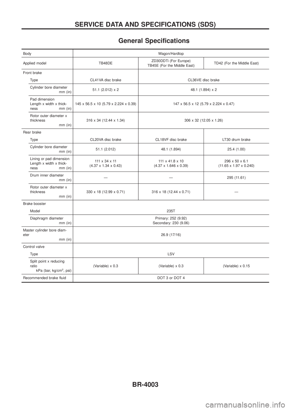
General Speci®cations
BodyWagon/Hardtop
Applied model TB48DEZD30DDTi (For Europe)
TB45E (For the Middle East)TD42 (For the Middle East)
Front brake
Type CL41VA disc brake CL36VE disc brake
Cylinder bore diameter
mm (in)51.1 (2.012) x 2 48.1 (1.894) x 2
Pad dimension
Length x width x thick-
ness mm (in)145 x 56.5 x 10 (5.79 x 2.224 x 0.39) 147 x 56.5 x 12 (5.79 x 2.224 x 0.47)
Rotor outer diameter x
thickness
mm (in)316 x 34 (12.44 x 1.34) 306 x 32 (12.05 x 1.26)
Rear brake
Type CL20VA disc brake CL18VF disc brake LT30 drum brake
Cylinder bore diameter
mm (in)51.1 (2.012) 48.1 (1.894) 25.4 (1.00)
Lining or pad dimension
Length x width x thick-
ness mm (in)111x34x11
(4.37 x 1.34 x 0.43)111x41.8x10
(4.37 x 1.646 x 0.39)296x50x6.1
(11.65 x 1.97 x 0.240)
Drum inner diameter
mm (in)Ð Ð 295 (11.61)
Rotor outer diameter x
thickness
mm (in)330 x 18 (12.99 x 0.71) 316 x 18 (12.44 x 0.71) Ð
Brake booster
Model235T
Diaphragm diameter
mm (in)Primary: 252 (9.92)
Secondary: 230 (9.06)
Master cylinder bore diam-
eter
mm (in)26.9 (17/16)
Control valve
TypeLSV
Split point x reducing
ratio
kPa (bar, kg/cm
2, psi)(Variable) x 0.3 (Variable) x 0.3 (Variable) x 0.15
Recommended brake ¯uid DOT 3 or DOT 4
SERVICE DATA AND SPECIFICATIONS (SDS)
BR-4003
Page 36 of 579
SECTION
EC
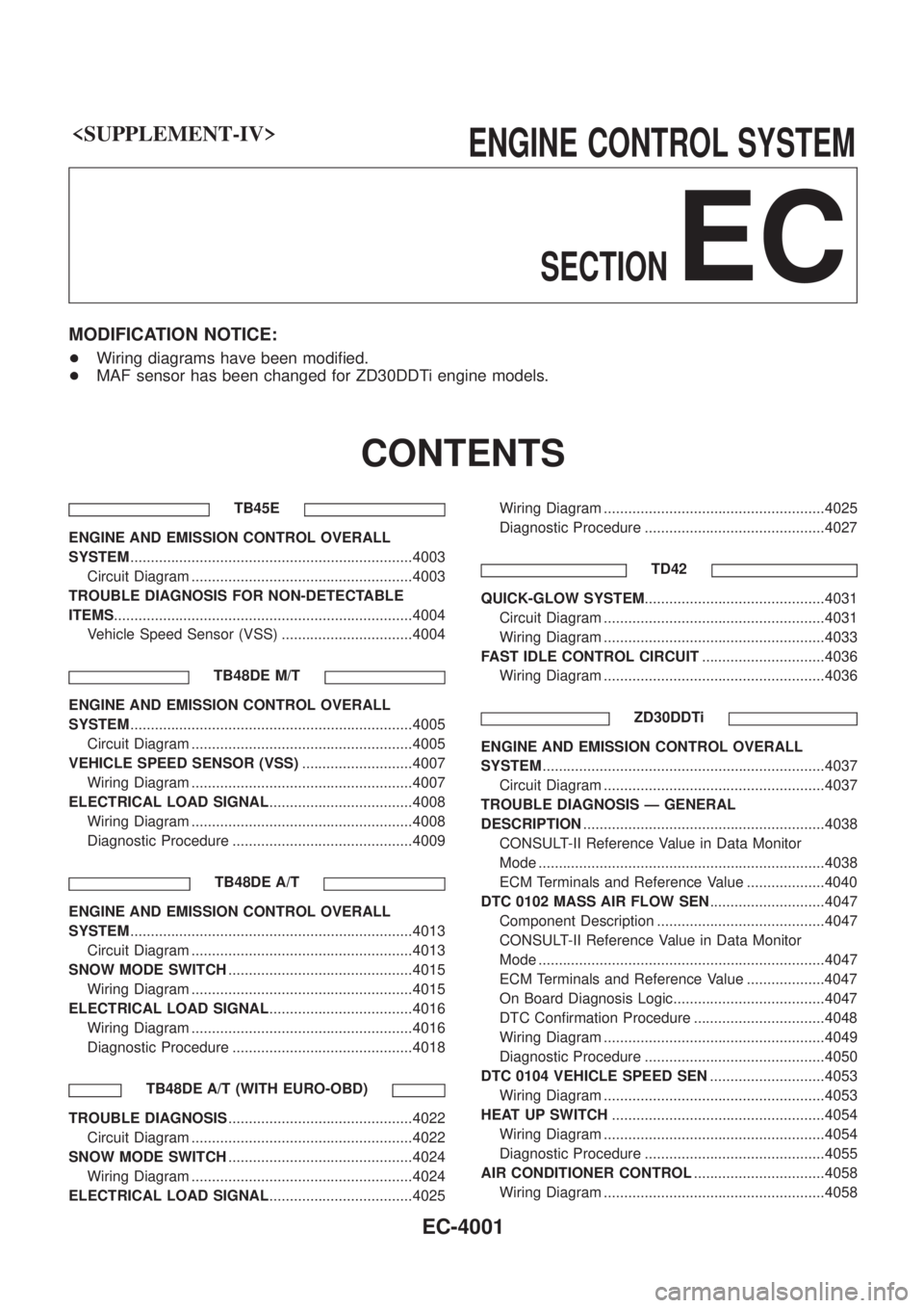
MODIFICATION NOTICE:
+Wiring diagrams have been modi®ed.
+ MAF sensor has been changed for ZD30DDTi engine models.
CONTENTS
TB45E
ENGINE AND EMISSION CONTROL OVERALL
SYSTEM .....................................................................4003
Circuit Diagram ......................................................4003
TROUBLE DIAGNOSIS FOR NON-DETECTABLE
ITEMS ........................................................................\
.4004
Vehicle Speed Sensor (VSS) ................................4004
TB48DE M/T
ENGINE AND EMISSION CONTROL OVERALL
SYSTEM.....................................................................4005
Circuit Diagram ......................................................4005
VEHICLE SPEED SENSOR (VSS) ...........................4007
Wiring Diagram ......................................................4007
ELECTRICAL LOAD SIGNAL ...................................4008
Wiring Diagram ......................................................4008
Diagnostic Procedure ............................................4009
TB48DE A/T
ENGINE AND EMISSION CONTROL OVERALL
SYSTEM.....................................................................4013
Circuit Diagram ......................................................4013
SNOW MODE SWITCH .............................................4015
Wiring Diagram ......................................................4015
ELECTRICAL LOAD SIGNAL ...................................4016
Wiring Diagram ......................................................4016
Diagnostic Procedure ............................................4018
TB48DE A/T (WITH EURO-OBD)
TROUBLE DIAGNOSIS .............................................4022
Circuit Diagram ......................................................4022
SNOW MODE SWITCH .............................................4024
Wiring Diagram ......................................................4024
ELECTRICAL LOAD SIGNAL ...................................4025 Wiring Diagram ......................................................4025
Diagnostic Procedure ............................................4027
TD42
QUICK-GLOW SYSTEM ............................................4031
Circuit Diagram ......................................................4031
Wiring Diagram ......................................................4033
FAST IDLE CONTROL CIRCUIT ..............................4036
Wiring Diagram ......................................................4036
ZD30DDTi
ENGINE AND EMISSION CONTROL OVERALL
SYSTEM.....................................................................4037
Circuit Diagram ......................................................4037
TROUBLE DIAGNOSIS Ð GENERAL
DESCRIPTION ...........................................................4038
CONSULT-II Reference Value in Data Monitor
Mode ......................................................................4038
ECM Terminals and Reference Value ...................4040
DTC 0102 MASS AIR FLOW SEN ............................4047
Component Description .........................................4047
CONSULT-II Reference Value in Data Monitor
Mode ......................................................................4047
ECM Terminals and Reference Value ...................4047
On Board Diagnosis Logic.....................................4047
DTC Con®rmation Procedure ................................4048
Wiring Diagram ......................................................4049
Diagnostic Procedure ............................................4050
DTC 0104 VEHICLE SPEED SEN ............................4053
Wiring Diagram ......................................................4053
HEAT UP SWITCH ....................................................4054
Wiring Diagram ......................................................4054
Diagnostic Procedure ............................................4055
AIR CONDITIONER CONTROL ................................4058
Wiring Diagram ......................................................4058
EC-4001
Page 74 of 579
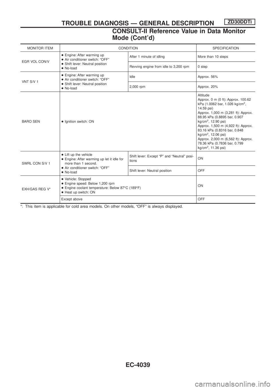
MONITOR ITEM CONDITION SPECIFICATION
EGR VOL CON/V+Engine: After warming up
+Air conditioner switch: ªOFFº
+Shift lever: Neutral position
+No-loadAfter 1 minute of idling More than 10 steps
Revving engine from idle to 3,200 rpm 0 step
VNT S/V 1+Engine: After warming up
+Air conditioner switch: ªOFFº
+Shift lever: Neutral position
+No-loadIdle Approx. 56%
2,000 rpm Approx. 20%
BARO SEN+Ignition switch: ONAltitude
Approx.0m(0ft): Approx. 100.62
kPa (1.0062 bar, 1.026 kg/cm
2,
14.59 psi)
Approx. 1,000 m (3,281 ft): Approx.
88.95 kPa (0.8895 bar, 0.907
kg/cm
2, 12.90 psi)
Approx. 1,500 m (4,922 ft): Approx.
83.16 kPa (0.8316 bar, 0.848
kg/cm
2, 12.06 psi)
Approx. 2,000 m (6,562 ft): Approx.
78.36 kPa (0.7836 bar, 0.799
kg/cm
2, 11.36 psi)
SWRL CON S/V 1+Lift up the vehicle
+Engine: After warming up let it idle for
more than 1 second.
+Air conditioner switch: ªOFFº
+No-loadShift lever: Except ªPº and ªNeutralº posi-
tionsON
Shift lever: Neutral position OFF
EXH/GAS REG V*+Vehicle: Stopped
+Engine speed: Below 1,200 rpm
+Engine coolant temperature: Below 87ÉC (189ÉF)
+Heat up switch: ONON
Except aboveOFF
*: This item is applicable for cold area models. On other models, ªOFFº is always displayed.
TROUBLE DIAGNOSIS Ð GENERAL DESCRIPTIONZD30DDTi
CONSULT-II Reference Value in Data Monitor
Mode (Cont'd)
EC-4039
Page 77 of 579
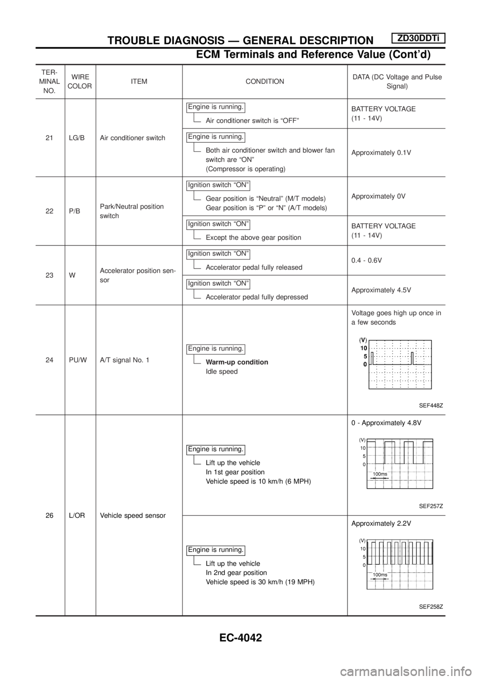
TER-
MINAL
NO.WIRE
COLORITEM CONDITIONDATA (DC Voltage and Pulse
Signal)
21 LG/B Air conditioner switchEngine is running.
Air conditioner switch is ªOFFºBATTERY VOLTAGE
(11 - 14V)
Engine is running.
Both air conditioner switch and blower fan
switch are ªONº
(Compressor is operating)Approximately 0.1V
22 P/BPark/Neutral position
switchIgnition switch ªONº
Gear position is ªNeutralº (M/T models)
Gear position is ªPº or ªNº (A/T models)Approximately 0V
Ignition switch ªONº
Except the above gear positionBATTERY VOLTAGE
(11 - 14V)
23 WAccelerator position sen-
sorIgnition switch ªONº
Accelerator pedal fully released0.4 - 0.6V
Ignition switch ªONº
Accelerator pedal fully depressedApproximately 4.5V
24 PU/W A/T signal No. 1Engine is running.
Warm-up condition
Idle speedVoltage goes high up once in
a few seconds
SEF448Z
26 L/OR Vehicle speed sensorEngine is running.
Lift up the vehicle
In 1st gear position
Vehicle speed is 10 km/h (6 MPH)0 - Approximately 4.8V
SEF257Z
Engine is running.
Lift up the vehicle
In 2nd gear position
Vehicle speed is 30 km/h (19 MPH)Approximately 2.2V
SEF258Z
TROUBLE DIAGNOSIS Ð GENERAL DESCRIPTIONZD30DDTi
ECM Terminals and Reference Value (Cont'd)
EC-4042
Page 83 of 579
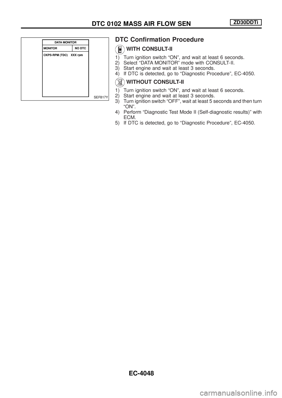
DTC Con®rmation Procedure
WITH CONSULT-II
1) Turn ignition switch ªONº, and wait at least 6 seconds.
2) Select ªDATA MONITORº mode with CONSULT-II.
3) Start engine and wait at least 3 seconds.
4) If DTC is detected, go to ªDiagnostic Procedureº, EC-4050.
WITHOUT CONSULT-II
1) Turn ignition switch ªONº, and wait at least 6 seconds.
2) Start engine and wait at least 3 seconds.
3) Turn ignition switch ªOFFº, wait at least 5 seconds and then turn
ªONº.
4) Perform ªDiagnostic Test Mode II (Self-diagnostic results)º with
ECM.
5) If DTC is detected, go to ªDiagnostic Procedureº, EC-4050.
SEF817Y
DTC 0102 MASS AIR FLOW SENZD30DDTi
EC-4048
Page 262 of 579
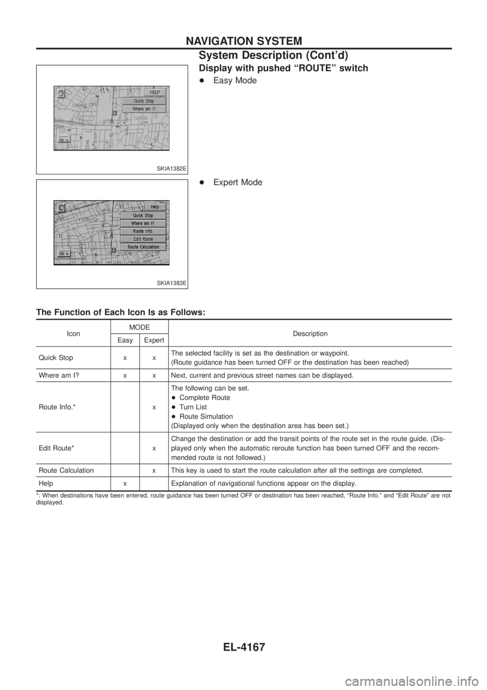
Display with pushed ªROUTEº switch
+Easy Mode
+ Expert Mode
The Function of Each Icon Is as Follows:
Icon MODE
Description
Easy Expert
Quick Stop x x The selected facility is set as the destination or waypoint.
(Route guidance has been turned OFF or the destination has been reached)
Where am I? x x Next, current and previous street names can be displayed.
Route Info.* x The following can be set.
+
Complete Route
+ Turn List
+ Route Simulation
(Displayed only when the destination area has been set.)
Edit Route* x Change the destination or add the transit points of the route set in the route guide. (Dis-
played only when the automatic reroute function has been turned OFF and the recom-
mended route is not followed.)
Route Calculation x This key is used to start the route calculation after all the settings are completed.
Help x Explanation of navigational functions appear on the display.
*: When destinations have been entered, route guidance has been turned OFF or destination has been reached, ªRoute Info.º and ªEdit Routeº are not
displayed.
SKIA1382E
SKIA1383E
NAVIGATION SYSTEM
System Description (Cont'd)
EL-4167