2004 NISSAN PATROL ECO mode
[x] Cancel search: ECO modePage 292 of 579
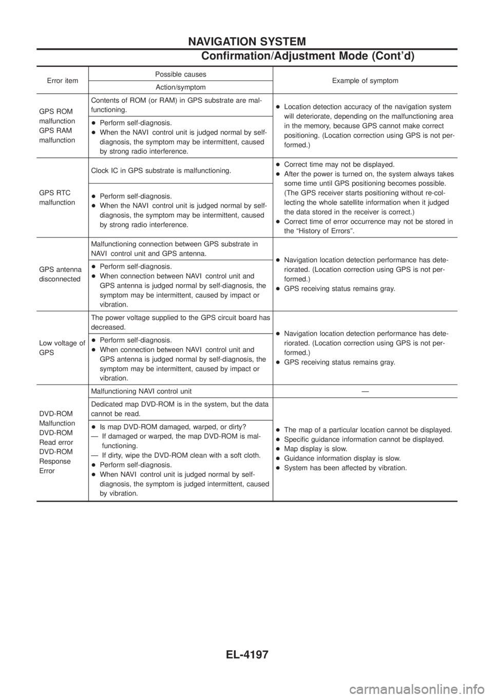
Error itemPossible causes
Example of symptom
Action/symptom
GPS ROM
malfunction
GPS RAM
malfunction Contents of ROM (or RAM) in GPS substrate are mal-
functioning.
+
Location detection accuracy of the navigation system
will deteriorate, depending on the malfunctioning area
in the memory, because GPS cannot make correct
positioning. (Location correction using GPS is not per-
formed.)
+
Perform self-diagnosis.
+ When the NAVI control unit is judged normal by self-
diagnosis, the symptom may be intermittent, caused
by strong radio interference.
GPS RTC
malfunction Clock IC in GPS substrate is malfunctioning.
+
Correct time may not be displayed.
+ After the power is turned on, the system always takes
some time until GPS positioning becomes possible.
(The GPS receiver starts positioning without re-col-
lecting the whole satellite information when it judged
the data stored in the receiver is correct.)
+ Correct time of error occurrence may not be stored in
the ªHistory of Errorsº.
+
Perform self-diagnosis.
+ When the NAVI control unit is judged normal by self-
diagnosis, the symptom may be intermittent, caused
by strong radio interference.
GPS antenna
disconnected Malfunctioning connection between GPS substrate in
NAVI control unit and GPS antenna.
+Navigation location detection performance has dete-
riorated. (Location correction using GPS is not per-
formed.)
+ GPS receiving status remains gray.
+
Perform self-diagnosis.
+ When connection between NAVI control unit and
GPS antenna is judged normal by self-diagnosis, the
symptom may be intermittent, caused by impact or
vibration.
Low voltage of
GPS The power voltage supplied to the GPS circuit board has
decreased.
+Navigation location detection performance has dete-
riorated. (Location correction using GPS is not per-
formed.)
+ GPS receiving status remains gray.
+
Perform self-diagnosis.
+ When connection between NAVI control unit and
GPS antenna is judged normal by self-diagnosis, the
symptom may be intermittent, caused by impact or
vibration.
DVD-ROM
Malfunction
DVD-ROM
Read error
DVD-ROM
Response
Error Malfunctioning NAVI control unit Ð
Dedicated map DVD-ROM is in the system, but the data
cannot be read.
+The map of a particular location cannot be displayed.
+ Speci®c guidance information cannot be displayed.
+ Map display is slow.
+ Guidance information display is slow.
+ System has been affected by vibration.
+
Is map DVD-ROM damaged, warped, or dirty?
Ð If damaged or warped, the map DVD-ROM is mal- functioning.
Ð If dirty, wipe the DVD-ROM clean with a soft cloth.
+ Perform self-diagnosis.
+ When NAVI control unit is judged normal by self-
diagnosis, the symptom is judged intermittent, caused
by vibration.
NAVIGATION SYSTEM
Con®rmation/Adjustment Mode (Cont'd)
EL-4197
Page 313 of 579
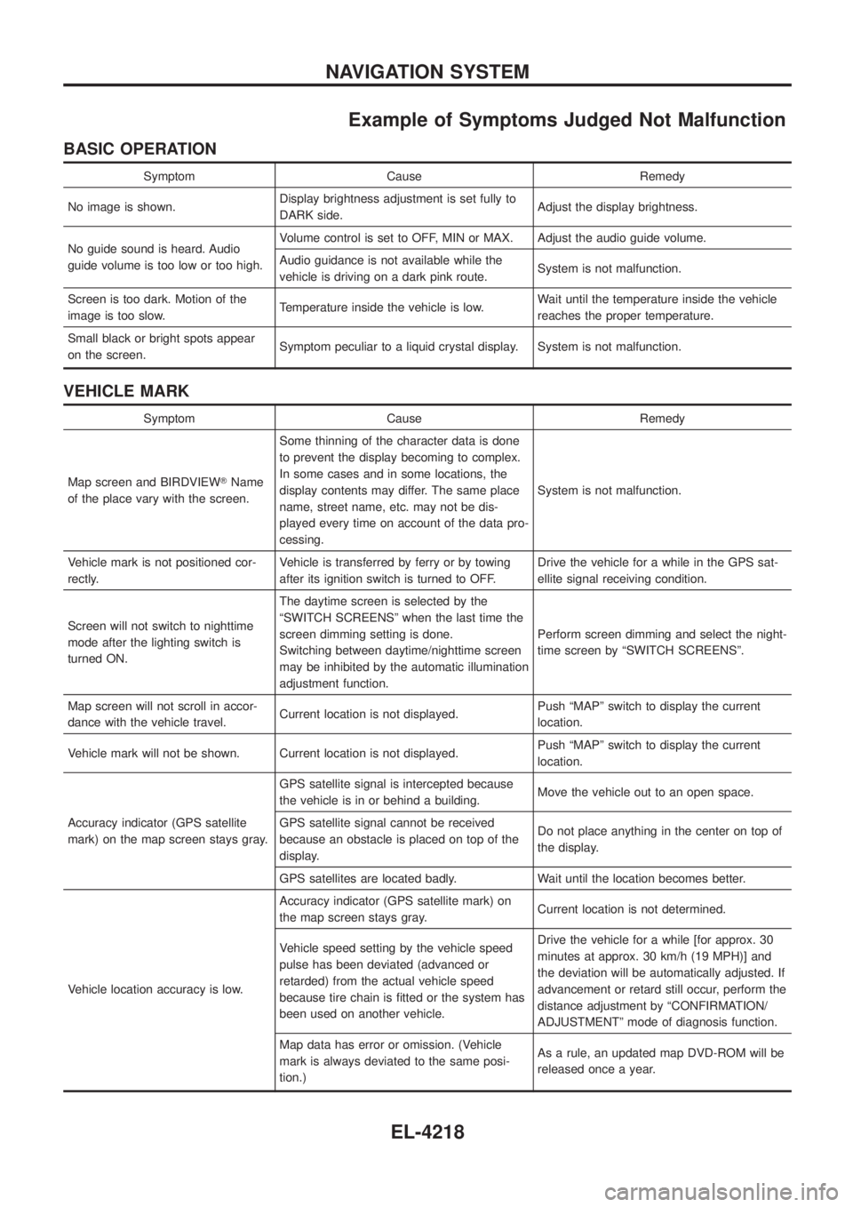
Example of Symptoms Judged Not Malfunction
BASIC OPERATION
Symptom Cause Remedy
No image is shown. Display brightness adjustment is set fully to
DARK side. Adjust the display brightness.
No guide sound is heard. Audio
guide volume is too low or too high. Volume control is set to OFF, MIN or MAX. Adjust the audio guide volume.
Audio guidance is not available while the
vehicle is driving on a dark pink route.
System is not malfunction.
Screen is too dark. Motion of the
image is too slow. Temperature inside the vehicle is low. Wait until the temperature inside the vehicle
reaches the proper temperature.
Small black or bright spots appear
on the screen. Symptom peculiar to a liquid crystal display. System is not malfunction.
VEHICLE MARK
Symptom Cause Remedy
Map screen and BIRDVIEW TName
of the place vary with the screen. Some thinning of the character data is done
to prevent the display becoming to complex.
In some cases and in some locations, the
display contents may differ. The same place
name, street name, etc. may not be dis-
played every time on account of the data pro-
cessing.
System is not malfunction.
Vehicle mark is not positioned cor-
rectly. Vehicle is transferred by ferry or by towing
after its ignition switch is turned to OFF. Drive the vehicle for a while in the GPS sat-
ellite signal receiving condition.
Screen will not switch to nighttime
mode after the lighting switch is
turned ON. The daytime screen is selected by the
ªSWITCH SCREENSº when the last time the
screen dimming setting is done.
Switching between daytime/nighttime screen
may be inhibited by the automatic illumination
adjustment function.
Perform screen dimming and select the night-
time screen by ªSWITCH SCREENSº.
Map screen will not scroll in accor-
dance with the vehicle travel. Current location is not displayed. Push ªMAPº switch to display the current
location.
Vehicle mark will not be shown. Current location is not displayed. Push ªMAPº switch to display the current
location.
Accuracy indicator (GPS satellite
mark) on the map screen stays gray. GPS satellite signal is intercepted because
the vehicle is in or behind a building.
Move the vehicle out to an open space.
GPS satellite signal cannot be received
because an obstacle is placed on top of the
display. Do not place anything in the center on top of
the display.
GPS satellites are located badly. Wait until the location becomes better.
Vehicle location accuracy is low. Accuracy indicator (GPS satellite mark) on
the map screen stays gray.
Current location is not determined.
Vehicle speed setting by the vehicle speed
pulse has been deviated (advanced or
retarded) from the actual vehicle speed
because tire chain is ®tted or the system has
been used on another vehicle. Drive the vehicle for a while [for approx. 30
minutes at approx. 30 km/h (19 MPH)] and
the deviation will be automatically adjusted. If
advancement or retard still occur, perform the
distance adjustment by ªCONFIRMATION/
ADJUSTMENTº mode of diagnosis function.
Map data has error or omission. (Vehicle
mark is always deviated to the same posi-
tion.) As a rule, an updated map DVD-ROM will be
released once a year.
NAVIGATION SYSTEM
EL-4218
Page 472 of 579
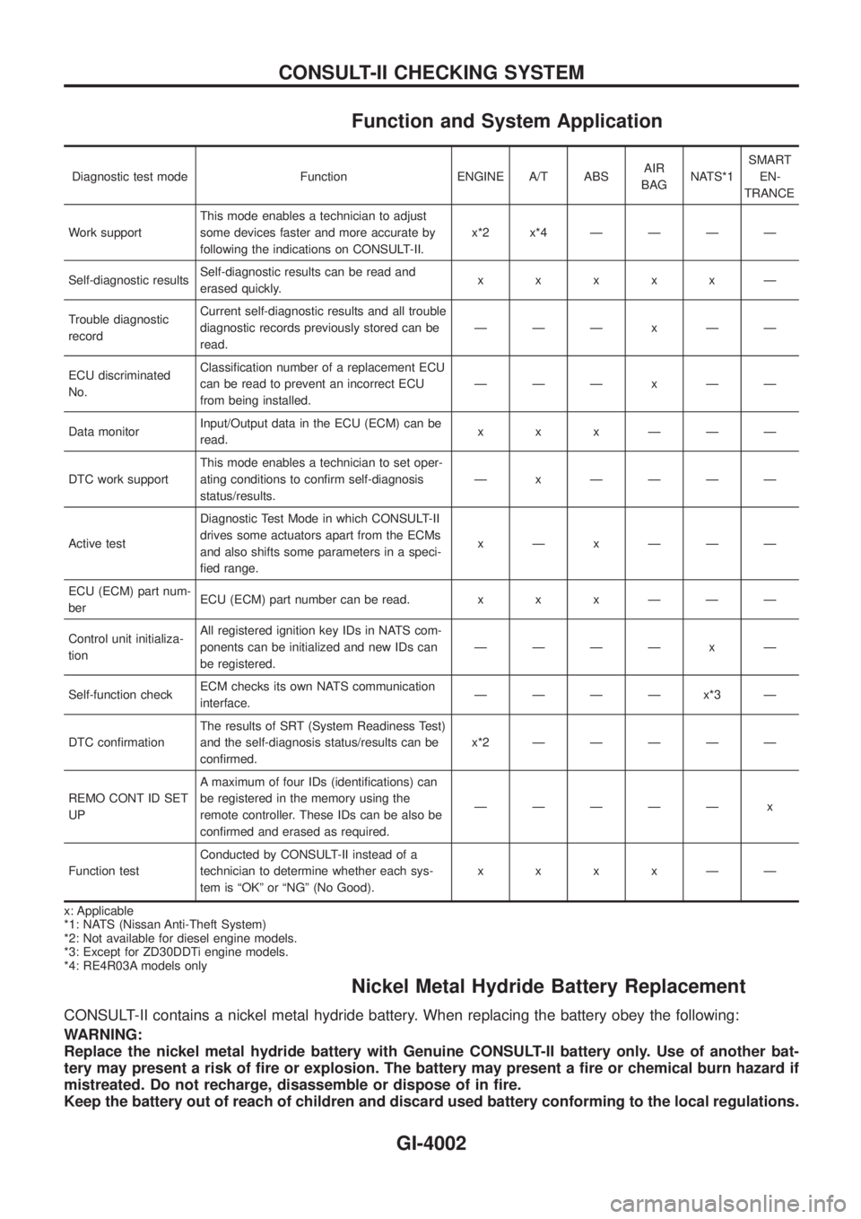
Function and System Application
Diagnostic test mode Function ENGINE A/T ABSAIR
BAGNATS*1SMART
EN-
TRANCE
Work supportThis mode enables a technician to adjust
some devices faster and more accurate by
following the indications on CONSULT-II.x*2x*4ÐÐÐÐ
Self-diagnostic resultsSelf-diagnostic results can be read and
erased quickly.xxxxxÐ
Trouble diagnostic
recordCurrent self-diagnostic results and all trouble
diagnostic records previously stored can be
read.ÐÐÐxÐÐ
ECU discriminated
No.Classi®cation number of a replacement ECU
can be read to prevent an incorrect ECU
from being installed.ÐÐÐxÐÐ
Data monitorInput/Output data in the ECU (ECM) can be
read.xxxÐÐÐ
DTC work supportThis mode enables a technician to set oper-
ating conditions to con®rm self-diagnosis
status/results.Ð x ÐÐÐÐ
Active testDiagnostic Test Mode in which CONSULT-II
drives some actuators apart from the ECMs
and also shifts some parameters in a speci-
®ed range.xÐxÐÐÐ
ECU (ECM) part num-
berECU (ECM) part number can be read. x x x Ð Ð Ð
Control unit initializa-
tionAll registered ignition key IDs in NATS com-
ponents can be initialized and new IDs can
be registered.ÐÐÐÐ x Ð
Self-function checkECM checks its own NATS communication
interface.ÐÐÐÐx*3Ð
DTC con®rmationThe results of SRT (System Readiness Test)
and the self-diagnosis status/results can be
con®rmed.x*2ÐÐÐÐÐ
REMO CONT ID SET
UPA maximum of four IDs (identi®cations) can
be registered in the memory using the
remote controller. These IDs can be also be
con®rmed and erased as required.ÐÐÐÐÐ x
Function testConducted by CONSULT-II instead of a
technician to determine whether each sys-
tem is ªOKº or ªNGº (No Good).xxxxÐÐ
x: Applicable
*1: NATS (Nissan Anti-Theft System)
*2: Not available for diesel engine models.
*3: Except for ZD30DDTi engine models.
*4: RE4R03A models only
Nickel Metal Hydride Battery Replacement
CONSULT-II contains a nickel metal hydride battery. When replacing the battery obey the following:
WARNING:
Replace the nickel metal hydride battery with Genuine CONSULT-II battery only. Use of another bat-
tery may present a risk of ®re or explosion. The battery may present a ®re or chemical burn hazard if
mistreated. Do not recharge, disassemble or dispose of in ®re.
Keep the battery out of reach of children and discard used battery conforming to the local regulations.
CONSULT-II CHECKING SYSTEM
GI-4002
Page 486 of 579
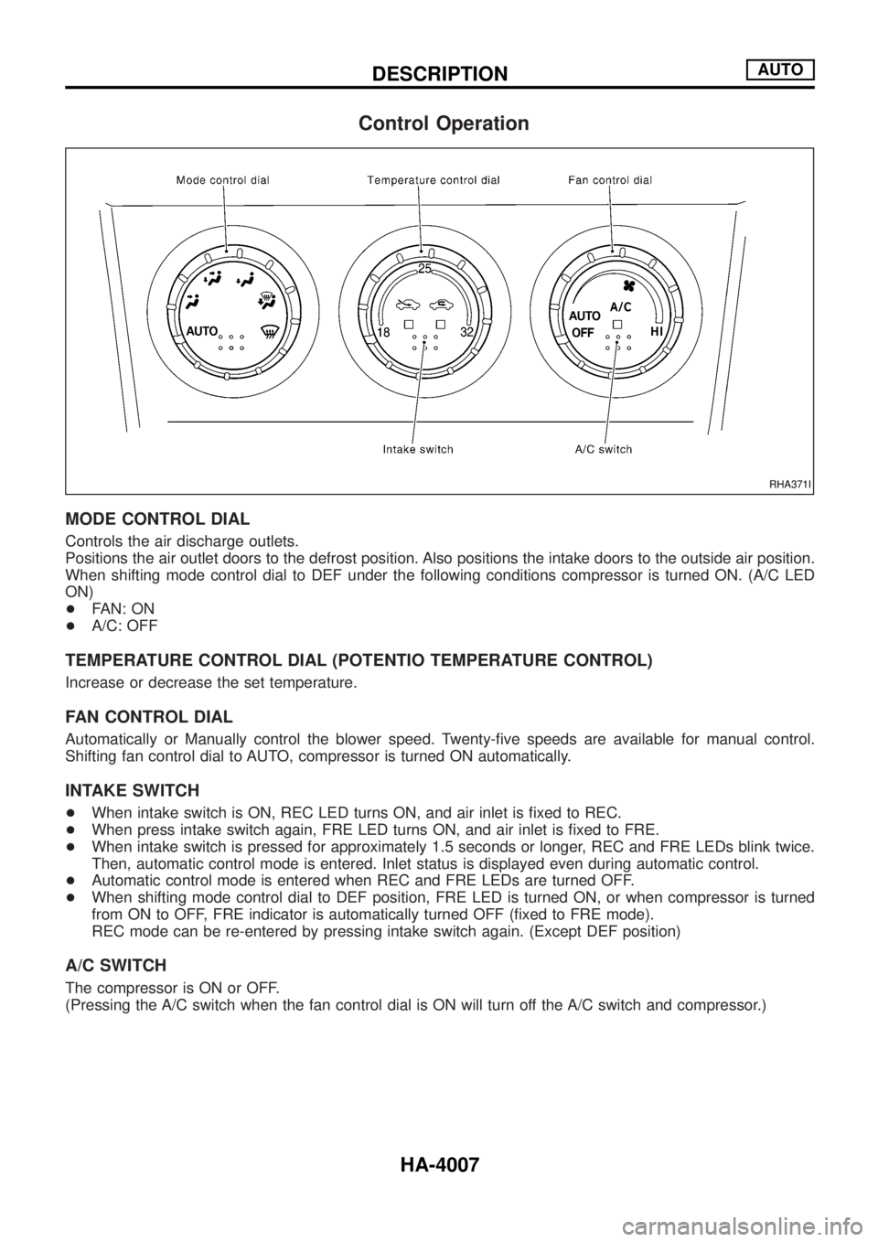
Control Operation
MODE CONTROL DIAL
Controls the air discharge outlets.
Positions the air outlet doors to the defrost position. Also positions the intake doors to the outside air position.
When shifting mode control dial to DEF under the following conditions compressor is turned ON. (A/C LED
ON)
+FAN: ON
+A/C: OFF
TEMPERATURE CONTROL DIAL (POTENTIO TEMPERATURE CONTROL)
Increase or decrease the set temperature.
FAN CONTROL DIAL
Automatically or Manually control the blower speed. Twenty-®ve speeds are available for manual control.
Shifting fan control dial to AUTO, compressor is turned ON automatically.
INTAKE SWITCH
+When intake switch is ON, REC LED turns ON, and air inlet is ®xed to REC.
+When press intake switch again, FRE LED turns ON, and air inlet is ®xed to FRE.
+When intake switch is pressed for approximately 1.5 seconds or longer, REC and FRE LEDs blink twice.
Then, automatic control mode is entered. Inlet status is displayed even during automatic control.
+Automatic control mode is entered when REC and FRE LEDs are turned OFF.
+When shifting mode control dial to DEF position, FRE LED is turned ON, or when compressor is turned
from ON to OFF, FRE indicator is automatically turned OFF (®xed to FRE mode).
REC mode can be re-entered by pressing intake switch again. (Except DEF position)
A/C SWITCH
The compressor is ON or OFF.
(Pressing the A/C switch when the fan control dial is ON will turn off the A/C switch and compressor.)
RHA371I
DESCRIPTIONAUTO
HA-4007
Page 506 of 579
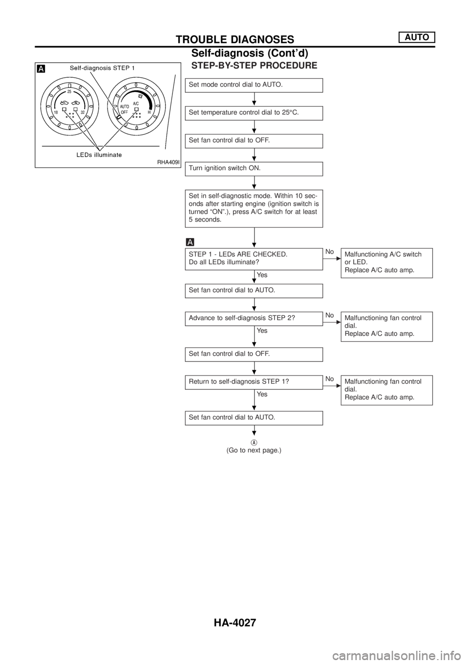
STEP-BY-STEP PROCEDURE
Set mode control dial to AUTO.
Set temperature control dial to 25ÉC.
Set fan control dial to OFF.
Turn ignition switch ON.
Set in self-diagnostic mode. Within 10 sec-
onds after starting engine (ignition switch is
turned ªONº.), press A/C switch for at least
5 seconds.
STEP 1 - LEDs ARE CHECKED.
Do all LEDs illuminate?
Ye s
cNo
Malfunctioning A/C switch
or LED.
Replace A/C auto amp.
Set fan control dial to AUTO.
Advance to self-diagnosis STEP 2?
Ye s
cNo
Malfunctioning fan control
dial.
Replace A/C auto amp.
Set fan control dial to OFF.
Return to self-diagnosis STEP 1?
Ye s
cNo
Malfunctioning fan control
dial.
Replace A/C auto amp.
Set fan control dial to AUTO.
jA
(Go to next page.)
RHA409I
.
.
.
.
.
.
.
.
.
.
.
TROUBLE DIAGNOSESAUTO
Self-diagnosis (Cont'd)
HA-4027
Page 510 of 579
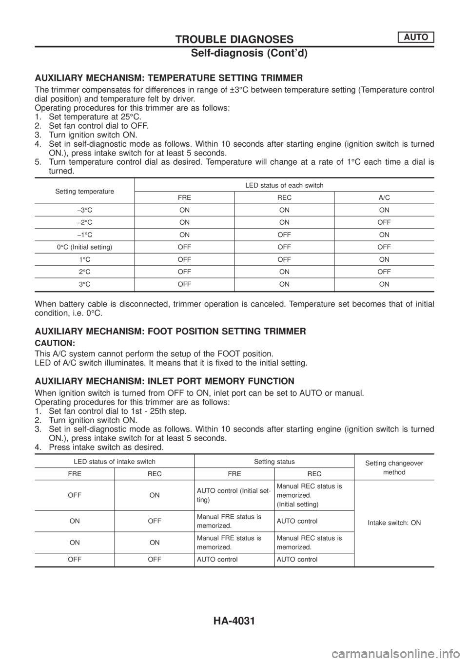
AUXILIARY MECHANISM: TEMPERATURE SETTING TRIMMER
The trimmer compensates for differences in range of 3ÉC between temperature setting (Temperature control
dial position) and temperature felt by driver.
Operating procedures for this trimmer are as follows:
1. Set temperature at 25ÉC.
2. Set fan control dial to OFF.
3. Turn ignition switch ON.
4. Set in self-diagnostic mode as follows. Within 10 seconds after starting engine (ignition switch is turned
ON.), press intake switch for at least 5 seconds.
5. Turn temperature control dial as desired. Temperature will change at a rate of 1ÉC each time a dial is
turned.
Setting temperatureLED status of each switch
FRE REC A/C
þ3ÉC ON ON ON
þ2ÉC ON ON OFF
þ1ÉC ON OFF ON
0ÉC (Initial setting) OFF OFF OFF
1ÉC OFF OFF ON
2ÉC OFF ON OFF
3ÉC OFF ON ON
When battery cable is disconnected, trimmer operation is canceled. Temperature set becomes that of initial
condition, i.e. 0ÉC.
AUXILIARY MECHANISM: FOOT POSITION SETTING TRIMMER
CAUTION:
This A/C system cannot perform the setup of the FOOT position.
LED of A/C switch illuminates. It means that it is ®xed to the initial setting.
AUXILIARY MECHANISM: INLET PORT MEMORY FUNCTION
When ignition switch is turned from OFF to ON, inlet port can be set to AUTO or manual.
Operating procedures for this trimmer are as follows:
1. Set fan control dial to 1st - 25th step.
2. Turn ignition switch ON.
3. Set in self-diagnostic mode as follows. Within 10 seconds after starting engine (ignition switch is turned
ON.), press intake switch for at least 5 seconds.
4. Press intake switch as desired.
LED status of intake switch Setting status
Setting changeover
method
FRE REC FRE REC
OFF ONAUTO control (Initial set-
ting)Manual REC status is
memorized.
(Initial setting)
Intake switch: ON ON OFFManual FRE status is
memorized.AUTO control
ON ONManual FRE status is
memorized.Manual REC status is
memorized.
OFF OFF AUTO control AUTO control
TROUBLE DIAGNOSESAUTO
Self-diagnosis (Cont'd)
HA-4031
Page 520 of 579
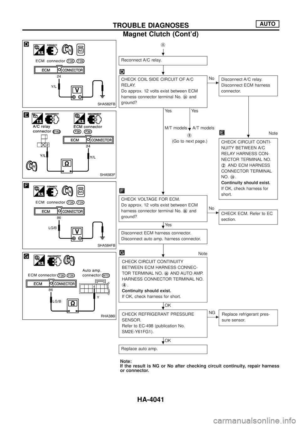
jA
Reconnect A/C relay.
CHECK COIL SIDE CIRCUIT OF A/C
RELAY.
Do approx. 12 volts exist between ECM
harness connector terminal No.j
24and
ground?
Ye s
Ye s
cNo
Disconnect A/C relay.
Disconnect ECM harness
connector.
jB
(Go to next page.)
Note
CHECK CIRCUIT CONTI-
NUITY BETWEEN A/C
RELAY HARNESS CON-
NECTOR TERMINAL NO.
j
2AND ECM HARNESS
CONNECTOR TERMINAL
NO.j
24.
Continuity should exist.
If OK, check harness for
short.
M/T models A/T models
CHECK VOLTAGE FOR ECM.
Do approx. 12 volts exist between ECM
harness connector terminal No.j
86and
ground?
Ye s
cNo
CHECK ECM. Refer to EC
section.
Disconnect ECM harness connector.
Disconnect auto amp. harness connector.
Note
CHECK CIRCUIT CONTINUITY
BETWEEN ECM HARNESS CONNEC-
TOR TERMINAL NO.j
86AND AUTO AMP.
HARNESS CONNECTOR TERMINAL NO.
j
4.
Continuity should exist.
If OK, check harness for short.
OK
CHECK REFRIGERANT PRESSURE
SENSOR.
Refer to EC-498 (publication No.
SM2E-Y61FG1).
OK
cNG
Replace refrigerant pres-
sure sensor.
Replace auto amp.
Note:
If the result is NG or No after checking circuit continuity, repair harness
or connector.
SHA582FB
SHA583F
SHA584FB
RHA386I
.
.
.
.
.
.
.
.
.
TROUBLE DIAGNOSESAUTO
Magnet Clutch (Cont'd)
HA-4041
Page 548 of 579
Illumination ..................................................EL-4079
Instrument panel .........................................BT-4006
Intake door motor .......................................HA-4037
Interior lamp ................................................EL-4088
K
Keyless entry system - See Multi-re-
mote control system ................................EL-4264
L
Length (Dimensions) ...................................GI-4008
License lamp ...............................................EL-4049
Line pressure test (A/T) ..............................AT-4014
LOAD - Wiring diagram .........EC-4008, 4016, 4025
Location of electrical units ..........................EL-4300
M
MAFS - Wiring diagram..............................EC-4049
Magnet clutch .............................................HA-4039
Maintenance...............................................MA-4003
Maintenance (engine) ................................MA-4003
Major overhaul (Transfer) .................TF-4002, 4003
Mass air ¯ow sensor (MAFS).....................EC-4047
Meter ...........................................................EL-4095
METER - Wiring diagram............................EL-4097
MIRROR - Wiring diagram..........................EL-4227
Mode door motor ........................................HA-4035
Model variation ............................................GI-4005
MULTI - Wiring diagram ...................EL-4264, 4266
Multi-remote control system........................EL-4264
N
NATS (Nissan anti-theft system) ......EL-4293, 4295
NATS - Wiring diagram ..........EL-4293, 4295, 4297
NAVI - Wiring diagram ................................EL-4175
Navigation System ......................................EL-4162
P
P/ANT - Wiring diagram..............................EL-4159
Parking lamp ...............................................EL-4049
POWER - Wiring diagram...........................EL-4006
Power door lock ..........................................EL-4244
Power supply routing ..................................EL-4005
Power window .............................................EL-4238
Pressure test (A/T) ......................................AT-4014Q
Quick-glow system .....................................EC-4031
R
Radio - See Audio.......................................EL-4136
R/COOL - Wiring diagram (front auto
A/C).........................................................HA-4055
R/COOL - Wiring diagram (front
manual A/C) ............................................HA-4057
Rear bumper ...............................................BT-4005
Rear seat ....................................................BT-4012
Rear seat belt .............................................RS-4013
Rear window defogger ................................EL-4126
REMOTE - Wiring diagram .........................EL-4155
R/FOG - Wiring diagram .............................EL-4064
R/HEAT - Wiring diagram ...........................HA-4003
Road wheel size ..........................................GI-4009
Room lamp - See Interior lamp ..................EL-4088
ROOM/L - Wiring diagram ..........................EL-4089
S
Seat belt, rear.............................................RS-4013
Seat, rear ....................................................BT-4012
Seat, second (2nd) .....................................BT-4012
Second (2nd) seat ......................................BT-4012
Shift schedule..............................................AT-4014
SMJ (super multiple junction) .......................Foldout
Speedometer...............................................EL-4095
SRS - Wiring diagram ................................RS-4003
STAB - Wiring diagram ..............................RA-4002
Stabilizer release device ............................RA-4002
Stabilizer release device - Wiring
diagram ...................................................RA-4002
Stall test (A/T) .............................................AT-4014
S/TANK - Wiring diagram ...........................FE-4004
Steering switch............................................EL-4036
Stop lamp ....................................................EL-4059
STOP/L - Wiring diagram............................EL-4059
Sub fuel tank control system ......................FE-4002
Super lock ...................................................EL-4290
Supplemental restraint system - Wiring
diagram ...................................................RS-4003
T
Tachometer .................................................EL-4095
Tail lamp ......................................................EL-4049
TAIL/L - Wiring diagram ..............................EL-4049
TCM circuit diagram ..........................AT-4002, 4011
Telephone....................................................EL-4161
THEFT - Wiring diagram ..................EL-4279, 4284
Theft warning system..................................EL-4278
ALPHABETICAL INDEX
IDX-4003