2004 NISSAN PATROL Transfer
[x] Cancel search: TransferPage 1 of 579
Edition: July 2004
Release: July 2004 (01)
Publication No.: SM4E00-1Y61E0E
Reference No.: 7711347233GENERAL INFORMATIONGI
MAINTENANCEMA
ENGINE MECHANICALEM
ENGINE LUBRICATION &
COOLING SYSTEMSLC
ENGINE CONTROL SYSTEMEC
ACCELERATOR CONTROL,
FUEL & EXHAUST SYSTEMFE
CLUTCHCL
MANUAL TRANSMISSIONMT
AUTOMATIC TRANSMISSIONAT
TRANSFERTF
PROPELLER SHAFT &
DIFFERENTIAL CARRIERPD
FRONT AXLE & FRONT SUSPENSIONFA
REAR AXLE & REAR SUSPENSIONRA
BRAKE SYSTEMBR
STEERING SYSTEMST
RESTRAINT SYSTEMRS
BODY & TRIMBT
HEATER & AIR CONDITIONERHA
ELECTRICAL SYSTEMEL
ALPHABETICAL INDEXIDX
PATROL
MODEL Y61 SERIES
NISSAN EUROPE S.A.S.
2004 NISSAN EUROPE S.A.S.
Produced in The Netherlands
Not to be reproduced in whole or in part
without the prior written permission of
Nissan Europe S.A.S., Paris, France.
QUICK REFERENCE INDEX
Page 98 of 579
Terminals and Reference Value for NAVI Control
Unit........................................................................\
.4183
Terminals and Reference Value for Display ..........4185
Terminals and Reference Value for NAVI Switch ..4186
Terminals and Reference Value for Transfer Unit .4187
Terminals and Reference Value for Voice
Change Relay ........................................................4188
Self-Diagnosis Function .........................................4189
Self-Diagnosis Mode..............................................4189
Con®rmation/Adjustment Mode .............................4192
Trouble Diagnoses.................................................4198
Example of Symptoms Judged Not Malfunction ...4218
Program Loading ...................................................4226
DOOR MIRROR/WAGON AND HARDTOP
MODELS ....................................................................4227
Wiring Diagram Ð MIRROR Ð/LHD Models........4227
Wiring Diagram Ð MIRROR Ð/RHD Models .......4229
HEATED SEAT/WAGON AND HARDTOP
MODELS ....................................................................4231
Wiring Diagram Ð HSEAT Ð................................4231
AUTOMATIC SPEED CONTROL DEVICE (ASCD)/
WAGON AND HARDTOP MODELS .........................4233
Schematic/TB48 and TD42Ti Engine Models .......4233
Wiring Diagram Ð ASCD Ð/TB48 and TD42Ti
Engine Models .......................................................4234
POWER WINDOW/WAGON AND HARDTOP
MODELS ....................................................................4238
Schematic ..............................................................4238
Wiring Diagram Ð WINDOW Ð ...........................4239
POWER DOOR LOCK/WAGON AND HARDTOP
MODELS ....................................................................4244
Schematic/Without Theft Warning System
Models ...................................................................4244
Wiring Diagram Ð D/LOCK Ð/Without Theft
Warning System Models ........................................4245
Schematic/With Theft Warning System Models ....4249
Wiring Diagram Ð D/LOCK Ð/LHD Models With
Theft Warning System ...........................................4250
Wiring Diagram Ð D/LOCK Ð/RHD Models With
Theft Warning System ...........................................4254
POWER DOOR LOCK/WAGON AND HARDTOP
MODELS ....................................................................4258
Schematic Ð Super Lock Ð .................................4258
Wiring Diagram Ð S/LOCK Ð ..............................4259
MULTI-REMOTE CONTROL SYSTEM/WAGON
AND HARDTOP MODELS ........................................4264
Wiring Diagram Ð MULTI Ð/LHD Models Except
for Europe, The Middle East and With Theft
Warning System ....................................................4264
Wiring Diagram Ð MULTI Ð/RHD Models
Except for Europe, South Africa and With Theft
Warning System ....................................................4266 Schematic/With Theft Warning System Models ....4268
Wiring Diagram Ð MULTI Ð/LHD Models with
Theft Warning System ...........................................4269
Wiring Diagram Ð MULTI Ð/RHD Models with
Theft Warning System ...........................................4273
Wiring Diagram Ð MULTI Ð/LHD Models for
Europe and The Middle East.................................4276
THEFT WARNING SYSTEM/WAGON AND
HARDTOP MODELS .................................................4278
Schematic ..............................................................4278
Wiring Diagram Ð THEFT Ð/LHD Models ...........4279
Wiring Diagram Ð THEFT Ð/RHD Models ..........4284
SUPER LOCK CONTROL UNIT/WAGON AND
HARDTOP MODELS .................................................4290
Schematic/RHD Models for Europe ......................4290
UNIFIED METER CONTROL UNIT (TIME
CONTROL SYSTEM)/WAGON AND HARDTOP
MODELS ....................................................................4292
Schematic/Except RHD Models for Europe and
With Theft Warning System Models ......................4292
NATS (Nissan Anti-Theft System)/TB48DE
ENGINE MODELS FOR EUROPE ............................4293
Wiring Diagram Ð NATS Ð ..................................4293
NATS (Nissan Anti-Theft System)/ZD ENGINE
MODELS ....................................................................4295
Wiring Diagram Ð NATS Ð/LHD Models for
Europe ...................................................................4295
Wiring Diagram Ð NATS Ð/RHD Models for
Europe ...................................................................4297
LOCATION OF ELECTRICAL UNITS/WAGON
AND HARDTOP MODELS ........................................4300
Engine Compartment .............................................4300
Passenger Compartment Ð LHD Models .............4302
Passenger Compartment Ð RHD Models ............4304
HARNESS LAYOUT ..................................................4307
How to Read Harness Layout ...............................4307
HARNESS LAYOUT/WAGON AND HARDTOP
MODELS ....................................................................4308
Main Harness/LHD Models....................................4308
Main Harness/RHD Models ...................................4312
Engine Room Harness/LHD Models .....................4316
Engine Room Harness/RHD Models .....................4322
Engine Harness .....................................................4328
Body Harness/LHD Models ...................................4330
Body Harness/RHD Models...................................4334
Body No. 2 Harness/LHD Models .........................4338
Body No. 2 Harness/RHD Models.........................4340
Chassis Harness....................................................4342
Front Door Harness (Driver side) ..........................4343
Front Door Harness (Passenger side) ..................4344
Rear Door Harness................................................4345
CONTENTS(Cont'd)
EL-4003
Page 282 of 579
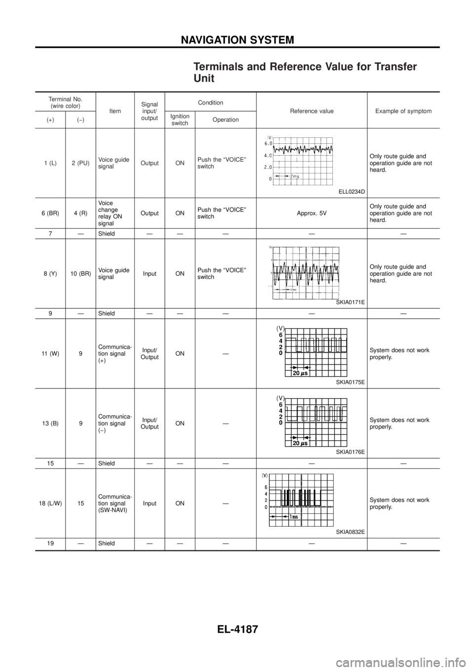
Terminals and Reference Value for Transfer
Unit
Terminal No.(wire color) ItemSignal
input/
output Condition
Reference value Example of symptom
(+) (þ) Ignition
switch Operation
1 (L) 2 (PU) Voice guide
signalOutput ON Push the ªVOICEº
switch
ELL0234D
Only route guide and
operation guide are not
heard.
6 (BR) 4 (R) Voice
change
relay ON
signalOutput ON
Push the ªVOICEº
switch Approx. 5VOnly route guide and
operation guide are not
heard.
7 Ð Shield Ð Ð Ð Ð Ð
8 (Y) 10 (BR) Voice guide
signalInput ON Push the ªVOICEº
switch
SKIA0171E
Only route guide and
operation guide are not
heard.
9 Ð Shield Ð Ð Ð Ð Ð
11 (W) 9 Communica-
tion signal
(+)Input/
Output ON Ð
SKIA0175E
System does not work
properly.
13 (B) 9 Communica-
tion signal
(þ)Input/
Output ON Ð
SKIA0176E
System does not work
properly.
15 Ð Shield Ð Ð Ð Ð Ð
18 (L/W) 15 Communica-
tion signal
(SW-NAVI)Input ON Ð
SKIA0832E
System does not work
properly.
19 Ð Shield Ð Ð Ð Ð Ð
NAVIGATION SYSTEM
EL-4187
Page 283 of 579
Terminal No.(wire color) ItemSignal
input/
output Condition
Reference value Example of symptom
(+) (þ) Ignition
switch Operation
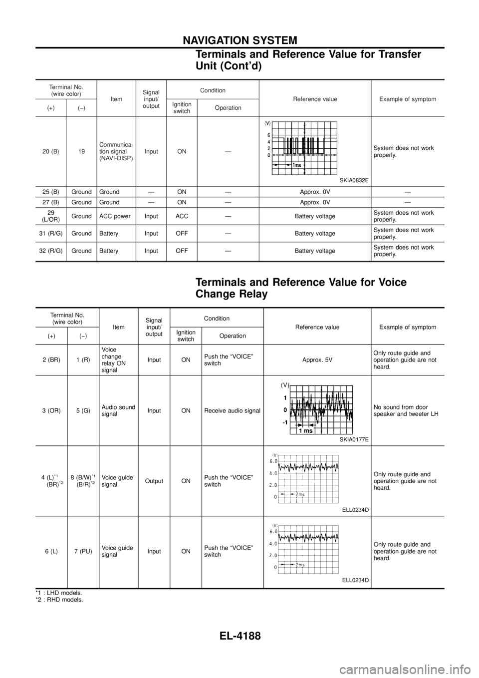
20 (B) 19 Communica-
tion signal
(NAVI-DISP)Input ON Ð
SKIA0832E
System does not work
properly.
25 (B) Ground Ground Ð ON Ð Approx. 0V Ð
27 (B) Ground Ground Ð ON Ð Approx. 0V Ð 29
(L/OR) Ground ACC power Input ACC Ð Battery voltage System does not work
properly.
31 (R/G) Ground Battery Input OFF Ð Battery voltage System does not work
properly.
32 (R/G) Ground Battery Input OFF Ð Battery voltage System does not work
properly.
Terminals and Reference Value for Voice
Change Relay
Terminal No.
(wire color) ItemSignal
input/
output Condition
Reference value Example of symptom
(+) (þ) Ignition
switch Operation
2 (BR) 1 (R) Voice
change
relay ON
signalInput ON
Push the ªVOICEº
switch Approx. 5VOnly route guide and
operation guide are not
heard.
3 (OR) 5 (G) Audio sound
signalInput ON Receive audio signal
SKIA0177E
No sound from door
speaker and tweeter LH
4 (L)
*1
(BR)*28 (B/W)*1
(B/R)*2Voice guide
signal Output ON Push the ªVOICEº
switch
ELL0234D
Only route guide and
operation guide are not
heard.
6 (L) 7 (PU) Voice guide
signalInput ON Push the ªVOICEº
switch
ELL0234D
Only route guide and
operation guide are not
heard.
*1 : LHD models.
*2 : RHD models.
NAVIGATION SYSTEM
Terminals and Reference Value for Transfer
Unit (Cont'd)
EL-4188
Page 285 of 579
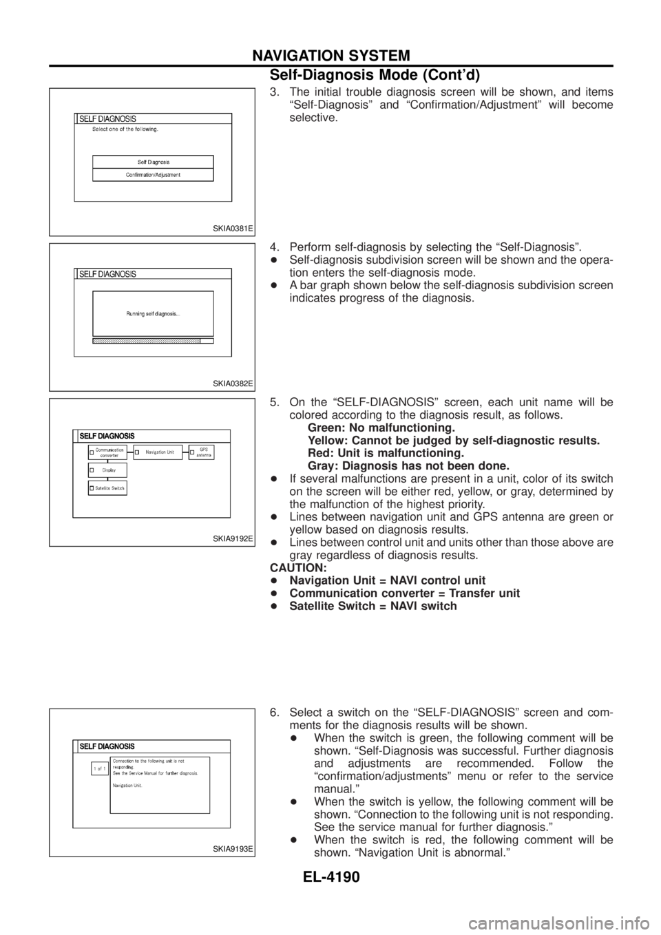
3. The initial trouble diagnosis screen will be shown, and itemsªSelf-Diagnosisº and ªCon®rmation/Adjustmentº will become
selective.
4. Perform self-diagnosis by selecting the ªSelf-Diagnosisº.
+ Self-diagnosis subdivision screen will be shown and the opera-
tion enters the self-diagnosis mode.
+ A bar graph shown below the self-diagnosis subdivision screen
indicates progress of the diagnosis.
5. On the ªSELF-DIAGNOSISº screen, each unit name will be colored according to the diagnosis result, as follows.Green: No malfunctioning.
Yellow: Cannot be judged by self-diagnostic results.
Red: Unit is malfunctioning.
Gray: Diagnosis has not been done.
+ If several malfunctions are present in a unit, color of its switch
on the screen will be either red, yellow, or gray, determined by
the malfunction of the highest priority.
+ Lines between navigation unit and GPS antenna are green or
yellow based on diagnosis results.
+ Lines between control unit and units other than those above are
gray regardless of diagnosis results.
CAUTION:
+ Navigation Unit = NAVI control unit
+ Communication converter = Transfer unit
+ Satellite Switch = NAVI switch
6. Select a switch on the ªSELF-DIAGNOSISº screen and com- ments for the diagnosis results will be shown.
+ When the switch is green, the following comment will be
shown. ªSelf-Diagnosis was successful. Further diagnosis
and adjustments are recommended. Follow the
ªcon®rmation/adjustmentsº menu or refer to the service
manual.º
+ When the switch is yellow, the following comment will be
shown. ªConnection to the following unit is not responding.
See the service manual for further diagnosis.º
+ When the switch is red, the following comment will be
shown. ªNavigation Unit is abnormal.º
SKIA0381E
SKIA0382E
SKIA9192E
SKIA9193E
NAVIGATION SYSTEM
Self-Diagnosis Mode (Cont'd)
EL-4190
Page 286 of 579
+When the switch is gray, the following comment will be
shown. ªSelf-diagnosis for DVD-ROM DRIVER of NAVI
was not conducted due to no insertion of DVD-ROM.º
SELF-DIAGNOSIS RESULT
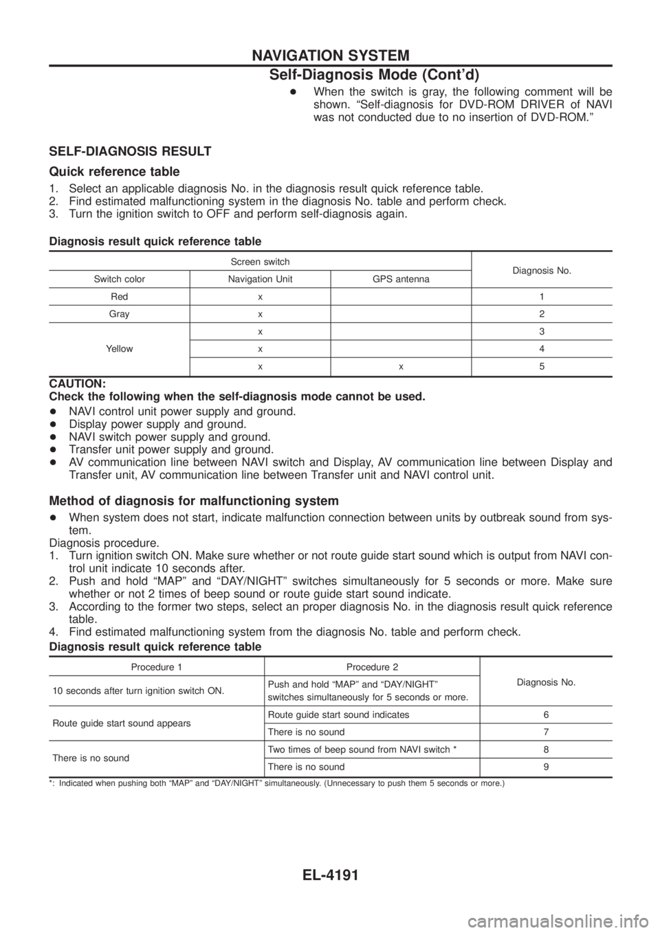
Quick reference table
1. Select an applicable diagnosis No. in the diagnosis result quick reference table.
2. Find estimated malfunctioning system in the diagnosis No. table and perform check.
3. Turn the ignition switch to OFF and perform self-diagnosis again.
Diagnosis result quick reference table
Screen switch
Diagnosis No.
Switch color Navigation Unit GPS antenna
Red x 1
Gray x 2
Yellow x3
x4
xx5
CAUTION:
Check the following when the self-diagnosis mode cannot be used.
+
NAVI control unit power supply and ground.
+ Display power supply and ground.
+ NAVI switch power supply and ground.
+ Transfer unit power supply and ground.
+ AV communication line between NAVI switch and Display, AV communication line between Display and
Transfer unit, AV communication line between Transfer unit and NAVI control unit.
Method of diagnosis for malfunctioning system
+When system does not start, indicate malfunction connection between units by outbreak sound from sys-
tem.
Diagnosis procedure.
1. Turn ignition switch ON. Make sure whether or not route guide start sound which is output from NAVI con- trol unit indicate 10 seconds after.
2. Push and hold ªMAPº and ªDAY/NIGHTº switches simultaneously for 5 seconds or more. Make sure whether or not 2 times of beep sound or route guide start sound indicate.
3. According to the former two steps, select an proper diagnosis No. in the diagnosis result quick reference table.
4. Find estimated malfunctioning system from the diagnosis No. table and perform check.
Diagnosis result quick reference table
Procedure 1 Procedure 2
Diagnosis No.
10 seconds after turn ignition switch ON. Push and hold ªMAPº and ªDAY/NIGHTº
switches simultaneously for 5 seconds or more.
Route guide start sound appears Route guide start sound indicates 6
There is no sound 7
There is no sound Two times of beep sound from NAVI switch * 8
There is no sound 9
*: Indicated when pushing both ªMAPº and ªDAY/NIGHTº simultaneously. (Unnecessary to push them 5 seconds or more.)
NAVIGATION SYSTEM
Self-Diagnosis Mode (Cont'd)
EL-4191
Page 287 of 579
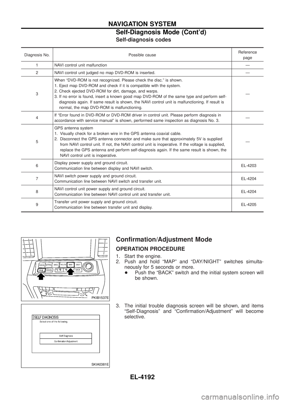
Self-diagnosis codes
Diagnosis No. Possible causeReference
page
1 NAVI control unit malfunction Ð
2 NAVI control unit judged no map DVD-ROM is inserted. Ð
3 When ªDVD-ROM is not recognized. Please check the disc.º is shown.
1. Eject map DVD-ROM and check if it is compatible with the system.
2. Check ejected DVD-ROM for dirt, damage, and warps.
3. If no error is found, insert a known good map DVD-ROM of the same type and perform self-
diagnosis again. If same result is shown, the NAVI control unit is malfunctioning. If result is
normal, the map DVD-ROM is malfunctioning. Ð
4 If ªError found in DVD-ROM or DVD-ROM driver in control unit. Please perform diagnosis in
accordance with service manualº is shown, performed same inspection as diagnosis No. 3. Ð
5 GPS antenna system
1. Visually check for a broken wire in the GPS antenna coaxial cable.
2. Disconnect the GPS antenna connector and make sure that approximately 5V is supplied
from NAVI control unit. If not, the NAVI control unit is inoperative. If the voltage is supplied,
replace the GPS antenna and perform self-diagnosis again. If the same result is shown, the
NAVI control unit is inoperative. Ð
6 Display power supply and ground circuit.
Communication line between display and NAVI switch. EL-4203
7 NAVI switch power supply and ground circuit.
Communication line between NAVI switch and transfer unit. EL-4204
8 NAVI control unit power supply and ground circuit.
Communication line between NAVI control unit and transfer unit. EL-4204
9 Transfer unit power supply and ground circuit.
Communication line between transfer unit and display. EL-4205
Con®rmation/Adjustment Mode
OPERATION PROCEDURE
1. Start the engine.
2. Push and hold ªMAPº and ªDAY/NIGHTº switches simulta-
neously for 5 seconds or more.
+ Push the ªBACKº switch and the initial system screen will
be shown.
3. The initial trouble diagnosis screen will be shown, and items ªSelf-Diagnosisº and ªCon®rmation/Adjustmentº will become
selective.
PKIB1537E
SKIA0381E
NAVIGATION SYSTEM
Self-Diagnosis Mode (Cont'd)
EL-4192
Page 297 of 579
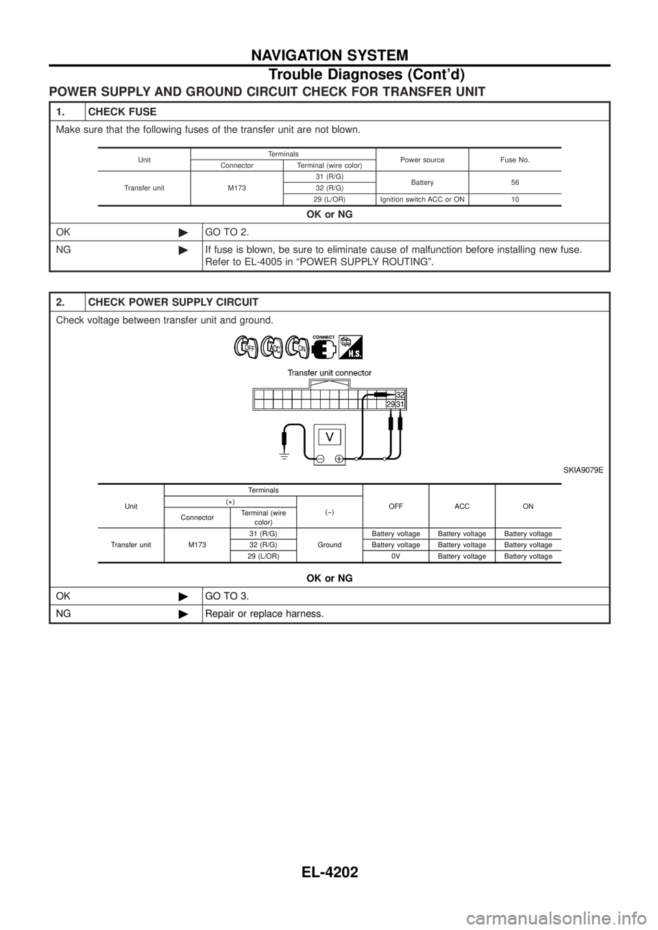
POWER SUPPLY AND GROUND CIRCUIT CHECK FOR TRANSFER UNIT
1. CHECK FUSE
Make sure that the following fuses of the transfer unit are not blown.OK or NG
OK ©GO TO 2.
NG ©If fuse is blown, be sure to eliminate cause of malfunction before installing new fuse.
Refer to EL-4005 in ªPOWER SUPPLY ROUTINGº.
Unit Terminals
Power source Fuse No.
Connector Terminal (wire color)
Transfer unit M173 31 (R/G)
Battery 56
32 (R/G)
29 (L/OR) Ignition switch ACC or ON 10
2. CHECK POWER SUPPLY CIRCUIT
Check voltage between transfer unit and ground.
SKIA9079E
OK or NG
OK ©GO TO 3.
NG ©Repair or replace harness.
Unit Terminals
OFF ACC ON
(+)
(þ)
Connector Terminal (wire
color)
Transfer unit M173 31 (R/G)
GroundBattery voltage Battery voltage Battery voltage
32 (R/G) Battery voltage Battery voltage Battery voltage
29 (L/OR) 0V Battery voltage Battery voltage
NAVIGATION SYSTEM
Trouble Diagnoses (Cont'd)
EL-4202