2004 NISSAN PATROL ECU
[x] Cancel search: ECUPage 22 of 579
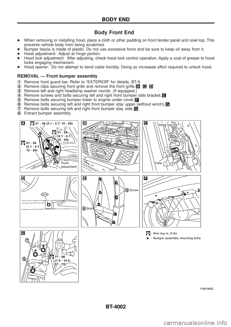
Body Front End
+When removing or installing hood, place a cloth or other padding on front fender panel and cowl top. This
prevents vehicle body from being scratched.
+Bumper fascia is made of plastic. Do not use excessive force and be sure to keep oil away from it.
+Hood adjustment: Adjust at hinge portion.
+Hood lock adjustment: After adjusting, check hood lock control operation. Apply a coat of grease to hood
locks engaging mechanism.
+Hood opener: Do not attempt to bend cable forcibly. Doing so increases effort required to unlock hood.
REMOVAL Ð Front bumper assembly
j1Remove front guard bar. Refer to ªEXTERIORº for details, BT-9.
j
2Remove clips securing front grille and remove the front grille.
j3Remove left and right headlamp washer nozzle. (If equipped.)
j
4Remove screws and bolts securing left and right front bumper side bracket.
j5Remove bolts securing bumper lower to engine under cover.
j6Remove bolts securing left and right front bumper stay upper (without winch).
j7Remove bolts securing left and right front bumper stay side.
j8Extract bumper assembly.
PIIB1965E
BODY END
BT-4002
Page 25 of 579
Body Rear End and Opener
+Bumper fascia is made of plastic. Do not use excessive force and be sure to keep oil away from it.
+Back door lock system adjustment: Adjust lock & striker so that they are in the center.
After adjustment, check back door lock operation.
+Back door hatch lock system adjustment: Adjust lock & striker so that they are in the center.
After adjustment, check back door hatch lock operation.
+Opener cable: Do not attempt to bend cable using excessive force.
+After installation, make sure that back door and fuel ®ller lid open smoothly.
WARNING:
+Be careful not to scratch back door stay and/or back door hatch stay when installing back door
and/or back door hatch. A scratched stay may cause gas leakage.
+The contents of the back door stay and back door hatch stay are under pressure. Do not take apart,
puncture, apply heat or allow ®re near them.
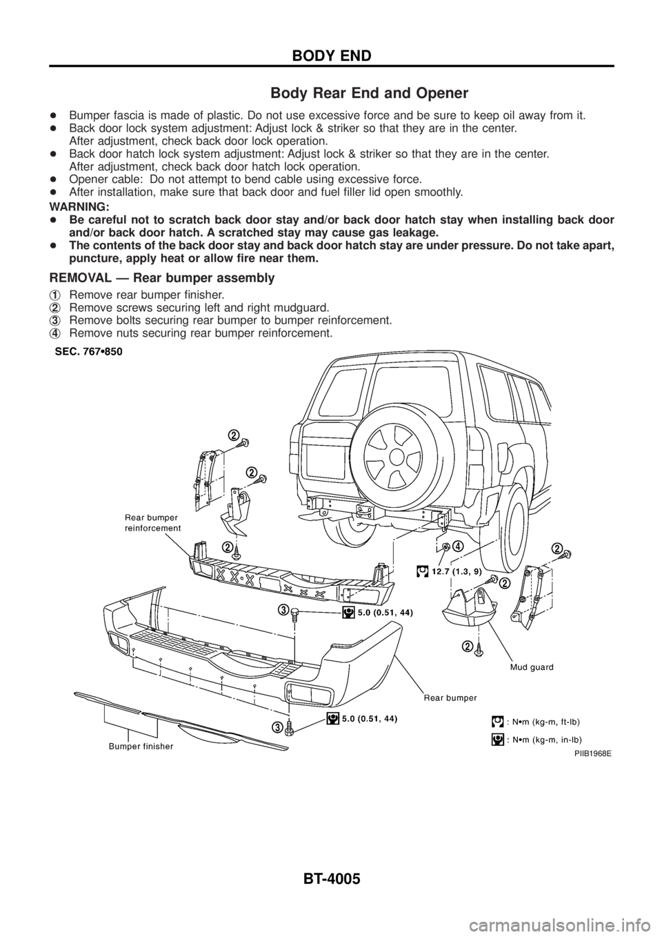
REMOVAL Ð Rear bumper assembly
j1Remove rear bumper ®nisher.
j
2Remove screws securing left and right mudguard.
j
3Remove bolts securing rear bumper to bumper reinforcement.
j
4Remove nuts securing rear bumper reinforcement.
PIIB1968E
BODY END
BT-4005
Page 34 of 579
Removal and Installation
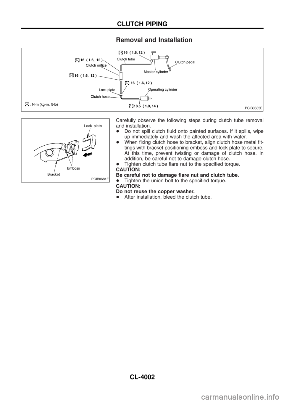
Carefully observe the following steps during clutch tube removal
and installation.
+Do not spill clutch ¯uid onto painted surfaces. If it spills, wipe
up immediately and wash the affected area with water.
+When ®xing clutch hose to bracket, align clutch hose metal ®t-
tings with bracket positioning emboss and lock plate to secure.
At this time, prevent twisting or damage of clutch hose. In
addition, be careful not to damage clutch hose.
+Tighten clutch tube ¯are nut to the speci®ed torque.
CAUTION:
Be careful not to damage ¯are nut and clutch tube.
+Tighten the union bolt to the speci®ed torque.
CAUTION:
Do not reuse the copper washer.
+After installation, bleed the clutch tube.
PCIB0685E
PCIB0681E
CLUTCH PIPING
CL-4002
Page 136 of 579
Bulb Replacement
CAUTION:
+After replacing a new xenon bulb, be sure to make aiming
adjustments.
+ Hold only the plastic base when handling the bulb. Never
touch the glass envelope.
+ Do not leave headlamp re¯ector without bulb for a long
period of time. Dust, moisture, smoke, etc. entering head-
lamp body may affect the performance of the headlamp.
Remove headlamp bulb from the headlamp re¯ector just
before a replacement bulb is installed.
1. Disconnect negative battery cable.
2. Remove side combination lamp and radiator grille.
3. Disconnect headlamp connector.
4. Remove headlamp assembly.
WARNING:
Never service a xenon headlamp with wet hands.
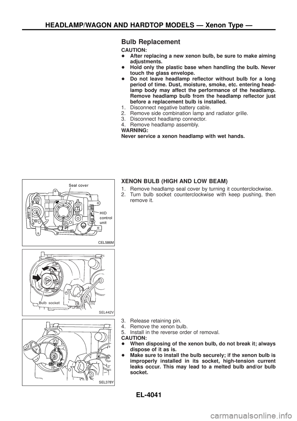
XENON BULB (HIGH AND LOW BEAM)
1. Remove headlamp seal cover by turning it counterclockwise.
2. Turn bulb socket counterclockwise with keep pushing, then remove it.
3. Release retaining pin.
4. Remove the xenon bulb.
5. Install in the reverse order of removal.
CAUTION:
+ When disposing of the xenon bulb, do not break it; always
dispose of it as is.
+ Make sure to install the bulb securely; if the xenon bulb is
improperly installed in its socket, high-tension current
leaks occur. This may lead to a melted bulb and/or bulb
socket.
CEL586M
SEL442V
SEL378Y
HEADLAMP/WAGON AND HARDTOP MODELS Ð Xenon Type Ð
EL-4041
Page 313 of 579
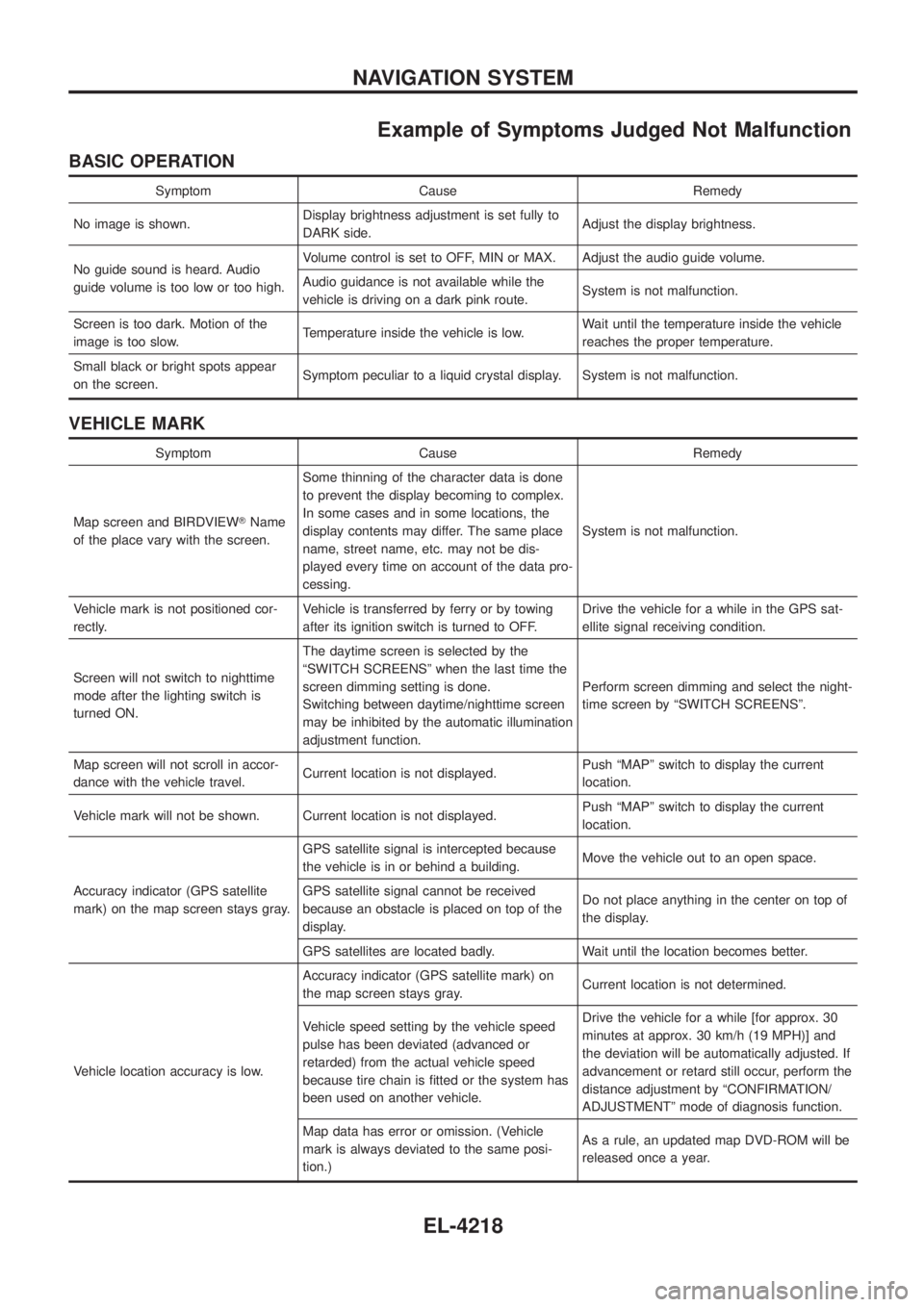
Example of Symptoms Judged Not Malfunction
BASIC OPERATION
Symptom Cause Remedy
No image is shown. Display brightness adjustment is set fully to
DARK side. Adjust the display brightness.
No guide sound is heard. Audio
guide volume is too low or too high. Volume control is set to OFF, MIN or MAX. Adjust the audio guide volume.
Audio guidance is not available while the
vehicle is driving on a dark pink route.
System is not malfunction.
Screen is too dark. Motion of the
image is too slow. Temperature inside the vehicle is low. Wait until the temperature inside the vehicle
reaches the proper temperature.
Small black or bright spots appear
on the screen. Symptom peculiar to a liquid crystal display. System is not malfunction.
VEHICLE MARK
Symptom Cause Remedy
Map screen and BIRDVIEW TName
of the place vary with the screen. Some thinning of the character data is done
to prevent the display becoming to complex.
In some cases and in some locations, the
display contents may differ. The same place
name, street name, etc. may not be dis-
played every time on account of the data pro-
cessing.
System is not malfunction.
Vehicle mark is not positioned cor-
rectly. Vehicle is transferred by ferry or by towing
after its ignition switch is turned to OFF. Drive the vehicle for a while in the GPS sat-
ellite signal receiving condition.
Screen will not switch to nighttime
mode after the lighting switch is
turned ON. The daytime screen is selected by the
ªSWITCH SCREENSº when the last time the
screen dimming setting is done.
Switching between daytime/nighttime screen
may be inhibited by the automatic illumination
adjustment function.
Perform screen dimming and select the night-
time screen by ªSWITCH SCREENSº.
Map screen will not scroll in accor-
dance with the vehicle travel. Current location is not displayed. Push ªMAPº switch to display the current
location.
Vehicle mark will not be shown. Current location is not displayed. Push ªMAPº switch to display the current
location.
Accuracy indicator (GPS satellite
mark) on the map screen stays gray. GPS satellite signal is intercepted because
the vehicle is in or behind a building.
Move the vehicle out to an open space.
GPS satellite signal cannot be received
because an obstacle is placed on top of the
display. Do not place anything in the center on top of
the display.
GPS satellites are located badly. Wait until the location becomes better.
Vehicle location accuracy is low. Accuracy indicator (GPS satellite mark) on
the map screen stays gray.
Current location is not determined.
Vehicle speed setting by the vehicle speed
pulse has been deviated (advanced or
retarded) from the actual vehicle speed
because tire chain is ®tted or the system has
been used on another vehicle. Drive the vehicle for a while [for approx. 30
minutes at approx. 30 km/h (19 MPH)] and
the deviation will be automatically adjusted. If
advancement or retard still occur, perform the
distance adjustment by ªCONFIRMATION/
ADJUSTMENTº mode of diagnosis function.
Map data has error or omission. (Vehicle
mark is always deviated to the same posi-
tion.) As a rule, an updated map DVD-ROM will be
released once a year.
NAVIGATION SYSTEM
EL-4218
Page 447 of 579
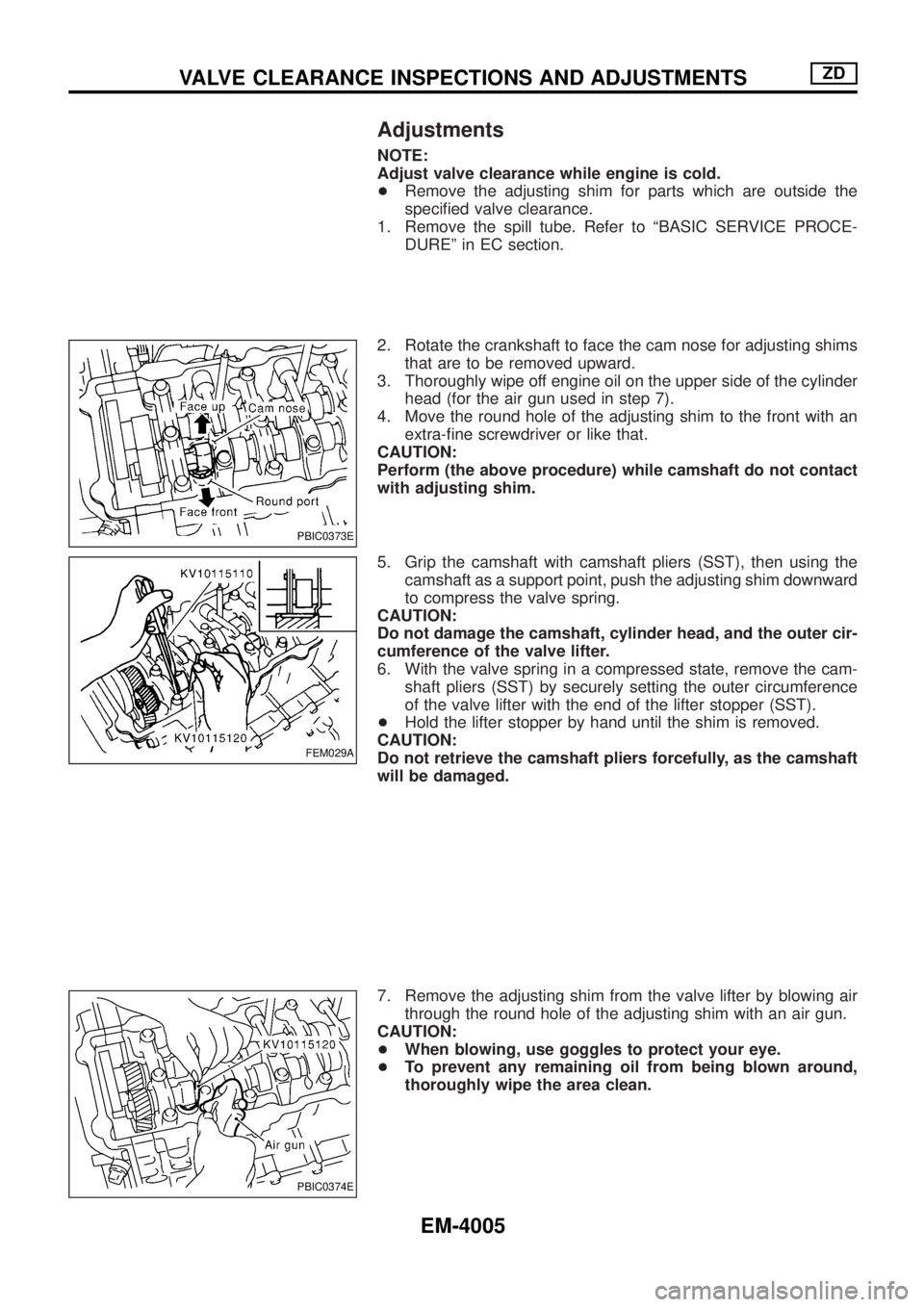
Adjustments
NOTE:
Adjust valve clearance while engine is cold.
+Remove the adjusting shim for parts which are outside the
speci®ed valve clearance.
1. Remove the spill tube. Refer to ªBASIC SERVICE PROCE-
DUREº in EC section.
2. Rotate the crankshaft to face the cam nose for adjusting shims
that are to be removed upward.
3. Thoroughly wipe off engine oil on the upper side of the cylinder
head (for the air gun used in step 7).
4. Move the round hole of the adjusting shim to the front with an
extra-®ne screwdriver or like that.
CAUTION:
Perform (the above procedure) while camshaft do not contact
with adjusting shim.
5. Grip the camshaft with camshaft pliers (SST), then using the
camshaft as a support point, push the adjusting shim downward
to compress the valve spring.
CAUTION:
Do not damage the camshaft, cylinder head, and the outer cir-
cumference of the valve lifter.
6. With the valve spring in a compressed state, remove the cam-
shaft pliers (SST) by securely setting the outer circumference
of the valve lifter with the end of the lifter stopper (SST).
+Hold the lifter stopper by hand until the shim is removed.
CAUTION:
Do not retrieve the camshaft pliers forcefully, as the camshaft
will be damaged.
7. Remove the adjusting shim from the valve lifter by blowing air
through the round hole of the adjusting shim with an air gun.
CAUTION:
+When blowing, use goggles to protect your eye.
+To prevent any remaining oil from being blown around,
thoroughly wipe the area clean.
PBIC0373E
FEM029A
PBIC0374E
VALVE CLEARANCE INSPECTIONS AND ADJUSTMENTSZD
EM-4005
Page 472 of 579
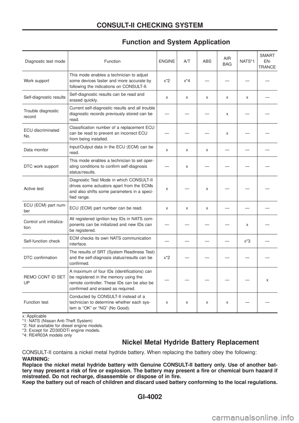
Function and System Application
Diagnostic test mode Function ENGINE A/T ABSAIR
BAGNATS*1SMART
EN-
TRANCE
Work supportThis mode enables a technician to adjust
some devices faster and more accurate by
following the indications on CONSULT-II.x*2x*4ÐÐÐÐ
Self-diagnostic resultsSelf-diagnostic results can be read and
erased quickly.xxxxxÐ
Trouble diagnostic
recordCurrent self-diagnostic results and all trouble
diagnostic records previously stored can be
read.ÐÐÐxÐÐ
ECU discriminated
No.Classi®cation number of a replacement ECU
can be read to prevent an incorrect ECU
from being installed.ÐÐÐxÐÐ
Data monitorInput/Output data in the ECU (ECM) can be
read.xxxÐÐÐ
DTC work supportThis mode enables a technician to set oper-
ating conditions to con®rm self-diagnosis
status/results.Ð x ÐÐÐÐ
Active testDiagnostic Test Mode in which CONSULT-II
drives some actuators apart from the ECMs
and also shifts some parameters in a speci-
®ed range.xÐxÐÐÐ
ECU (ECM) part num-
berECU (ECM) part number can be read. x x x Ð Ð Ð
Control unit initializa-
tionAll registered ignition key IDs in NATS com-
ponents can be initialized and new IDs can
be registered.ÐÐÐÐ x Ð
Self-function checkECM checks its own NATS communication
interface.ÐÐÐÐx*3Ð
DTC con®rmationThe results of SRT (System Readiness Test)
and the self-diagnosis status/results can be
con®rmed.x*2ÐÐÐÐÐ
REMO CONT ID SET
UPA maximum of four IDs (identi®cations) can
be registered in the memory using the
remote controller. These IDs can be also be
con®rmed and erased as required.ÐÐÐÐÐ x
Function testConducted by CONSULT-II instead of a
technician to determine whether each sys-
tem is ªOKº or ªNGº (No Good).xxxxÐÐ
x: Applicable
*1: NATS (Nissan Anti-Theft System)
*2: Not available for diesel engine models.
*3: Except for ZD30DDTi engine models.
*4: RE4R03A models only
Nickel Metal Hydride Battery Replacement
CONSULT-II contains a nickel metal hydride battery. When replacing the battery obey the following:
WARNING:
Replace the nickel metal hydride battery with Genuine CONSULT-II battery only. Use of another bat-
tery may present a risk of ®re or explosion. The battery may present a ®re or chemical burn hazard if
mistreated. Do not recharge, disassemble or dispose of in ®re.
Keep the battery out of reach of children and discard used battery conforming to the local regulations.
CONSULT-II CHECKING SYSTEM
GI-4002
Page 575 of 579
Rear Seat Belt
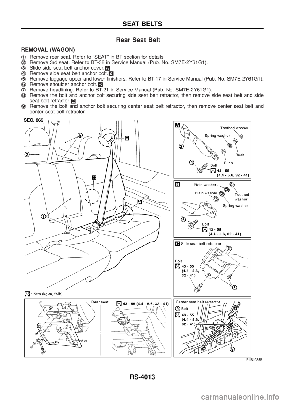
REMOVAL (WAGON)
j1Remove rear seat. Refer to ªSEATº in BT section for details.
j
2Remove 3rd seat. Refer to BT-38 in Service Manual (Pub. No. SM7E-2Y61G1).
j
3Slide side seat belt anchor cover.
j4Remove side seat belt anchor bolt.
j5Remove luggage upper and lower ®nishers. Refer to BT-17 in Service Manual (Pub. No. SM7E-2Y61G1).
j
6Remove shoulder anchor bolt.
j7Remove headlining. Refer to BT-21 in Service Manual (Pub. No. SM7E-2Y61G1).
j
8Remove the bolt and anchor bolt securing side seat belt retractor, then remove side seat belt and side
seat belt retractor.
j9Remove the bolt and anchor bolt securing center seat belt retractor, then remove center seat belt and
center seat belt retractor.
PIIB1985E
SEAT BELTS
RS-4013