2004 NISSAN PATROL service
[x] Cancel search: servicePage 2 of 579
FOREWORD
This manual contains maintenance and repair procedures for NISSAN
PATROL,modelY61 series.
In order to assure your safety and the efficient functioning of the vehicle,
this manual should be read thoroughly. It is especially important that the
PRECAUTIONS in the GI section be completely understood before starting
any repair task.
All information in this manual is based on the latest product information
at the time of publication. The right is reserved to make changes in speci-
®cations and methods at any time without notice.
IMPORTANT SAFETY NOTICE
The proper performance of service is essential for both the safety of the
technician and the efficient functioning of the vehicle.
The service methods in this Service Manual are described in such a man-
ner that the service may be performed safely and accurately.
Service varies with the procedures used, the skills of the technician and the
tools and parts available. Accordingly, anyone using service procedures,
tools or parts which are not speci®cally recommended by NISSAN must
®rst completely satisfy himself that neither his safety nor the vehicle's
safety will be jeopardized by the service method selected.
NISSAN EUROPE S.A.S.
Service Engineering SectionParis, France
Page 3 of 579
SECTION
AT
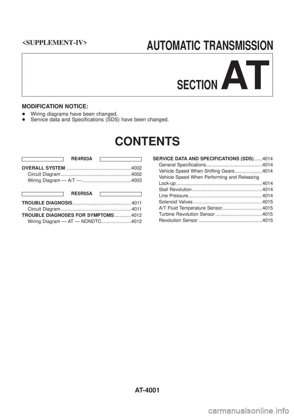
MODIFICATION NOTICE:
+Wiring diagrams have been changed.
+ Service data and Speci®cations (SDS) have been changed.
CONTENTS
RE4R03A
OVERALL SYSTEM ..................................................4002
Circuit Diagram ......................................................4002
Wiring Diagram Ð A/T Ð ......................................4003
RE5R05A
TROUBLE DIAGNOSIS ............................................. 4011
Circuit Diagram ...................................................... 4011
TROUBLE DIAGNOSES FOR SYMPTOMS .............4012
Wiring Diagram Ð AT Ð NONDTC.......................4012 SERVICE DATA AND SPECIFICATIONS (SDS)
......4014
General Speci®cations ...........................................4014
Vehicle Speed When Shifting Gears .....................4014
Vehicle Speed When Performing and Releasing
Lock-up ..................................................................4014
Stall Revolution ......................................................4014
Line Pressure.........................................................4014
Solenoid Valves .....................................................4015
A/T Fluid Temperature Sensor...............................4015
Turbine Revolution Sensor ....................................4015
Revolution Sensor .................................................4015
AT-4001
Page 16 of 579
General Speci®cations
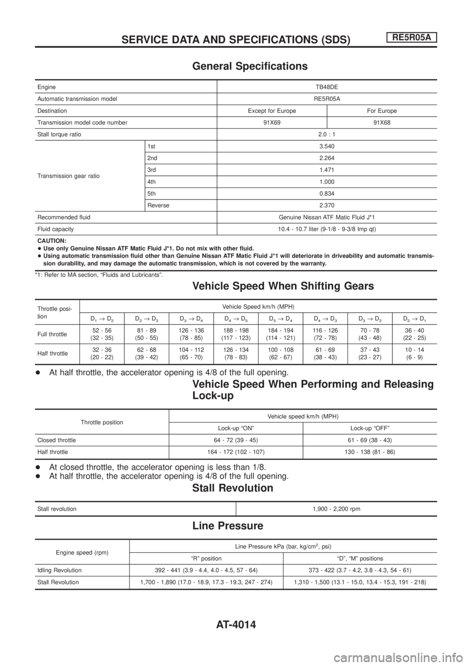
EngineTB48DE
Automatic transmission modelRE5R05A
Destination Except for Europe For Europe
Transmission model code number 91X69 91X68
Stall torque ratio2.0:1
Transmission gear ratio1st 3.540
2nd 2.264
3rd 1.471
4th 1.000
5th 0.834
Reverse 2.370
Recommended ¯uid Genuine Nissan ATF Matic Fluid J*1
Fluid capacity10.4 - 10.7 liter (9-1/8 - 9-3/8 Imp qt)
CAUTION:
+Use only Genuine Nissan ATF Matic Fluid J*1. Do not mix with other ¯uid.
+Using automatic transmission ¯uid other than Genuine Nissan ATF Matic Fluid J*1 will deteriorate in driveability and automatic transmis-
sion durability, and may damage the automatic transmission, which is not covered by the warranty.
*1: Refer to MA section, ªFluids and Lubricantsº.
Vehicle Speed When Shifting Gears
Throttle posi-
tionVehicle Speed km/h (MPH)
D
1®D2D2®D3D3®D4D4®D5D5®D4D4®D3D3®D2D2®D1
Full throttle52-56
(32 - 35)81-89
(50 - 55)126 - 136
(78 - 85)188 - 198
(117 - 123)184 - 194
(114 - 121)116 - 126
(72 - 78)70-78
(43 - 48)36-40
(22 - 25)
Half throttle32-36
(20 - 22)62-68
(39 - 42)104 - 112
(65 - 70)126 - 134
(78 - 83)100 - 108
(62 - 67)61-69
(38 - 43)37-43
(23 - 27)10-14
(6-9)
+At half throttle, the accelerator opening is 4/8 of the full opening.
Vehicle Speed When Performing and Releasing
Lock-up
Throttle positionVehicle speed km/h (MPH)
Lock-up ªONº Lock-up ªOFFº
Closed throttle 64 - 72 (39 - 45) 61 - 69 (38 - 43)
Half throttle 164 - 172 (102 - 107) 130 - 138 (81 - 86)
+At closed throttle, the accelerator opening is less than 1/8.
+At half throttle, the accelerator opening is 4/8 of the full opening.
Stall Revolution
Stall revolution1,900 - 2,200 rpm
Line Pressure
Engine speed (rpm)Line Pressure kPa (bar, kg/cm
2, psi)
ªRº position ªDº, ªMº positions
Idling Revolution 392 - 441 (3.9 - 4.4, 4.0 - 4.5, 57 - 64) 373 - 422 (3.7 - 4.2, 3.8 - 4.3, 54 - 61)
Stall Revolution 1,700 - 1,890 (17.0 - 18.9, 17.3 - 19.3, 247 - 274) 1,310 - 1,500 (13.1 - 15.0, 13.4 - 15.3, 191 - 218)
SERVICE DATA AND SPECIFICATIONS (SDS)RE5R05A
AT-4014
Page 17 of 579
Solenoid Valves
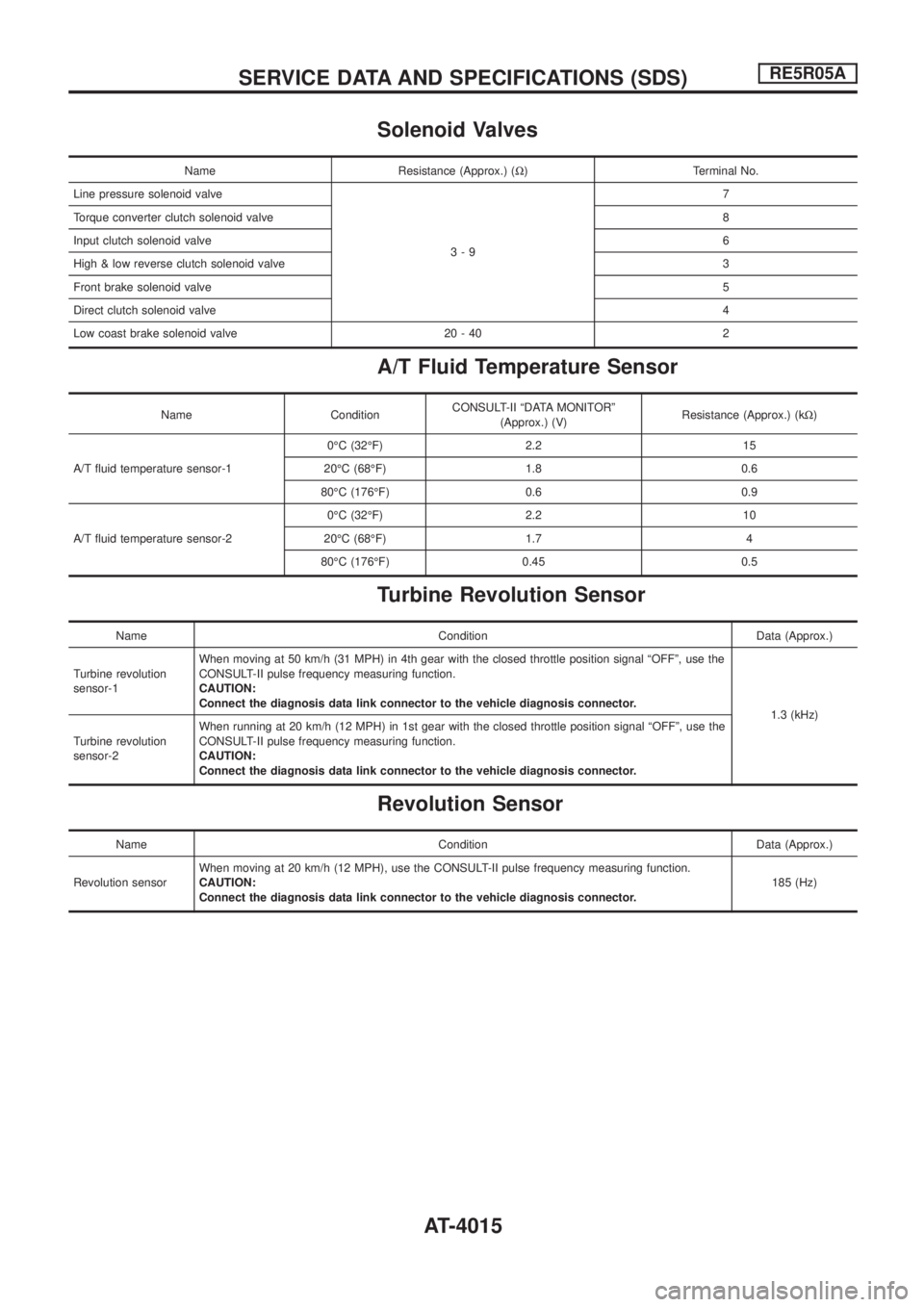
Name Resistance (Approx.) (W) Terminal No.
Line pressure solenoid valve
3-97
Torque converter clutch solenoid valve8
Input clutch solenoid valve6
High & low reverse clutch solenoid valve3
Front brake solenoid valve5
Direct clutch solenoid valve4
Low coast brake solenoid valve 20 - 40 2
A/T Fluid Temperature Sensor
Name ConditionCONSULT-II ªDATA MONITORº
(Approx.) (V)Resistance (Approx.) (kW)
A/T ¯uid temperature sensor-10ÉC (32ÉF) 2.2 15
20ÉC (68ÉF) 1.8 0.6
80ÉC (176ÉF) 0.6 0.9
A/T ¯uid temperature sensor-20ÉC (32ÉF) 2.2 10
20ÉC (68ÉF) 1.7 4
80ÉC (176ÉF) 0.45 0.5
Turbine Revolution Sensor
Name Condition Data (Approx.)
Turbine revolution
sensor-1When moving at 50 km/h (31 MPH) in 4th gear with the closed throttle position signal ªOFFº, use the
CONSULT-II pulse frequency measuring function.
CAUTION:
Connect the diagnosis data link connector to the vehicle diagnosis connector.
1.3 (kHz)
Turbine revolution
sensor-2When running at 20 km/h (12 MPH) in 1st gear with the closed throttle position signal ªOFFº, use the
CONSULT-II pulse frequency measuring function.
CAUTION:
Connect the diagnosis data link connector to the vehicle diagnosis connector.
Revolution Sensor
Name Condition Data (Approx.)
Revolution sensorWhen moving at 20 km/h (12 MPH), use the CONSULT-II pulse frequency measuring function.
CAUTION:
Connect the diagnosis data link connector to the vehicle diagnosis connector.185 (Hz)
SERVICE DATA AND SPECIFICATIONS (SDS)RE5R05A
AT-4015
Page 18 of 579
SECTION
BR
MODIFICATION NOTICE:
+ Engine direction indicator stamp has been added to brake booster hose.
+ Service data and speci®cations (SDS) have been changed.
CONTENTS
VACUUM PIPING .......................................................4002
Vacuum Hose ........................................................4002 SERVICE DATA AND SPECIFICATIONS (SDS)
......4003
General Speci®cations ...........................................4003
BR-4001
Page 20 of 579
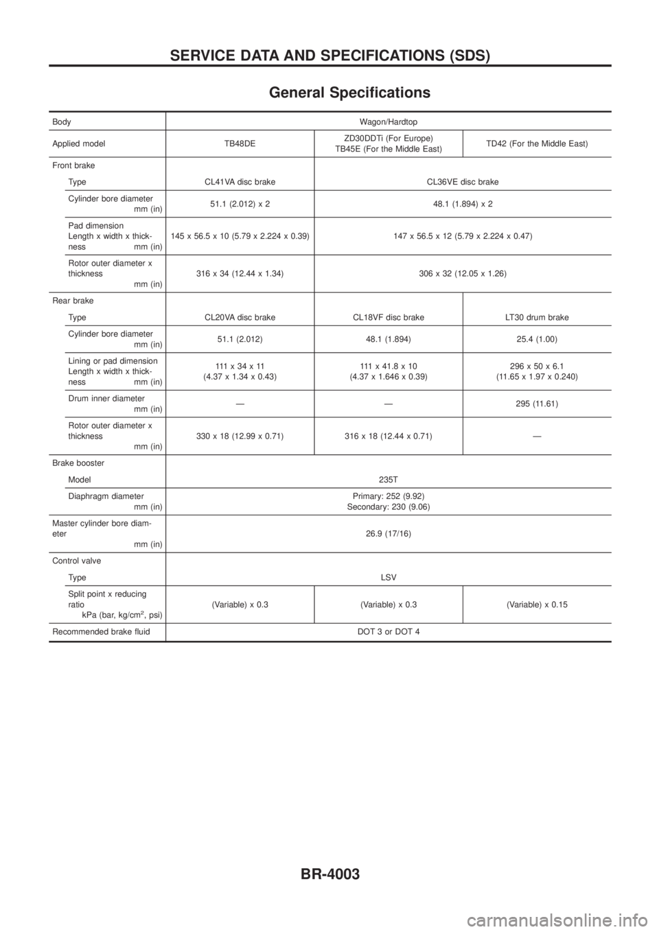
General Speci®cations
BodyWagon/Hardtop
Applied model TB48DEZD30DDTi (For Europe)
TB45E (For the Middle East)TD42 (For the Middle East)
Front brake
Type CL41VA disc brake CL36VE disc brake
Cylinder bore diameter
mm (in)51.1 (2.012) x 2 48.1 (1.894) x 2
Pad dimension
Length x width x thick-
ness mm (in)145 x 56.5 x 10 (5.79 x 2.224 x 0.39) 147 x 56.5 x 12 (5.79 x 2.224 x 0.47)
Rotor outer diameter x
thickness
mm (in)316 x 34 (12.44 x 1.34) 306 x 32 (12.05 x 1.26)
Rear brake
Type CL20VA disc brake CL18VF disc brake LT30 drum brake
Cylinder bore diameter
mm (in)51.1 (2.012) 48.1 (1.894) 25.4 (1.00)
Lining or pad dimension
Length x width x thick-
ness mm (in)111x34x11
(4.37 x 1.34 x 0.43)111x41.8x10
(4.37 x 1.646 x 0.39)296x50x6.1
(11.65 x 1.97 x 0.240)
Drum inner diameter
mm (in)Ð Ð 295 (11.61)
Rotor outer diameter x
thickness
mm (in)330 x 18 (12.99 x 0.71) 316 x 18 (12.44 x 0.71) Ð
Brake booster
Model235T
Diaphragm diameter
mm (in)Primary: 252 (9.92)
Secondary: 230 (9.06)
Master cylinder bore diam-
eter
mm (in)26.9 (17/16)
Control valve
TypeLSV
Split point x reducing
ratio
kPa (bar, kg/cm
2, psi)(Variable) x 0.3 (Variable) x 0.3 (Variable) x 0.15
Recommended brake ¯uid DOT 3 or DOT 4
SERVICE DATA AND SPECIFICATIONS (SDS)
BR-4003
Page 26 of 579
CAUTION:
+Disconnect both battery cables in advance.
+Disconnect air bag system line in advance.
+Never tamper with or force air bag lid open, as this may adversely affect air bag performance.
+Be careful not to scratch pad and other parts.
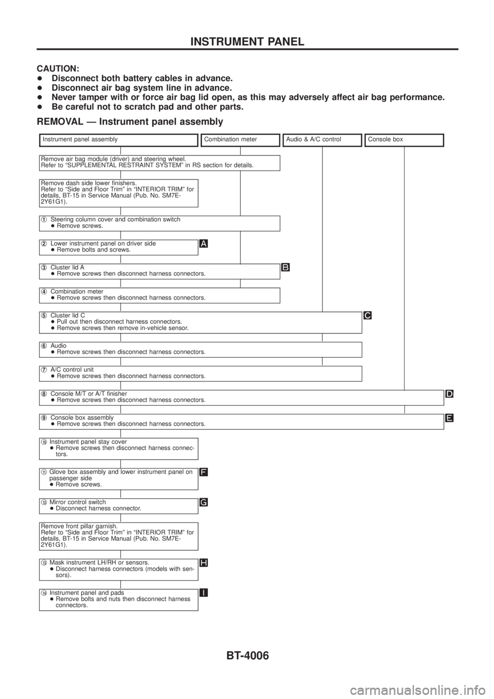
REMOVAL Ð Instrument panel assembly
Instrument panel assemblyCombination meterAudio & A/C controlConsole box
Remove air bag module (driver) and steering wheel.
Refer to ªSUPPLEMENTAL RESTRAINT SYSTEMº in RS section for details.
Remove dash side lower ®nishers.
Refer to ªSide and Floor Trimº in ªINTERIOR TRIMº for
details, BT-15 in Service Manual (Pub. No. SM7E-
2Y61G1).
j1Steering column cover and combination switch
+Remove screws.
j2Lower instrument panel on driver side
+Remove bolts and screws.
j3Cluster lid A
+Remove screws then disconnect harness connectors.
j4Combination meter
+Remove screws then disconnect harness connectors.
j5Cluster lid C
+Pull out then disconnect harness connectors.
+Remove screws then remove in-vehicle sensor.
j6Audio
+Remove screws then disconnect harness connectors.
j7A/C control unit
+Remove screws then disconnect harness connectors.
j8Console M/T or A/T ®nisher
+Remove screws then disconnect harness connectors.
j9Console box assembly
+Remove screws then disconnect harness connectors.
j10Instrument panel stay cover
+Remove screws then disconnect harness connec-
tors.
j11Glove box assembly and lower instrument panel on
passenger side
+Remove screws.
j12Mirror control switch
+Disconnect harness connector.
Remove front pillar garnish.
Refer to ªSide and Floor Trimº in ªINTERIOR TRIMº for
details, BT-15 in Service Manual (Pub. No. SM7E-
2Y61G1).
j13Mask instrument LH/RH or sensors.
+Disconnect harness connectors (models with sen-
sors).
j14Instrument panel and pads
+Remove bolts and nuts then disconnect harness
connectors.
INSTRUMENT PANEL
BT-4006
Page 33 of 579
CLUTCH
SECTION
CL
MODIFICATION NOTICE:
+ Clutch cover has been changed, and clutch ori®ce has been added to 2-door models based on the grade
of ZD30DDTi engine.
+ Service Data and Speci®cations (SDS) have been changed.
CONTENTS
CLUTCH PIPING .......................................................4002
Removal and Installation .......................................4002
SERVICE DATA AND SPECIFICATIONS (SDS) ......4003General Speci®cations ...........................................4003
Inspection and Adjustment ....................................4003
CL-4001