Page 451 of 579
Removal
1. Remove the following parts.
+Undercover
+Engine oil (Drain)
+Engine coolant (Drain)
+Engine cover
+Intercooler
+Air inlet pipe
+Air cleaner case
+Throttle body
+Swirl and intake air control valve control solenoid valve and
bracket
+Vacuum tank
+Glow plate
+Rocker cover
+Spill tube
+Radiator shrouds (Rear and Lower)
+Cooling fan
+Radiator hose (Upper and Lower)
+Auxiliary belt and auto tensioner.
2. Remove the alternator.
3. Remove the A/C compressor and bracket with piping con-
nected. Move and support it at the LH side of engine bay with
a rope to avoid putting load on piping.
Refer to HA section in NISSAN Service Manual (Publication No.
SM9E-Y61CG2 or SM9E-Y61CG3).
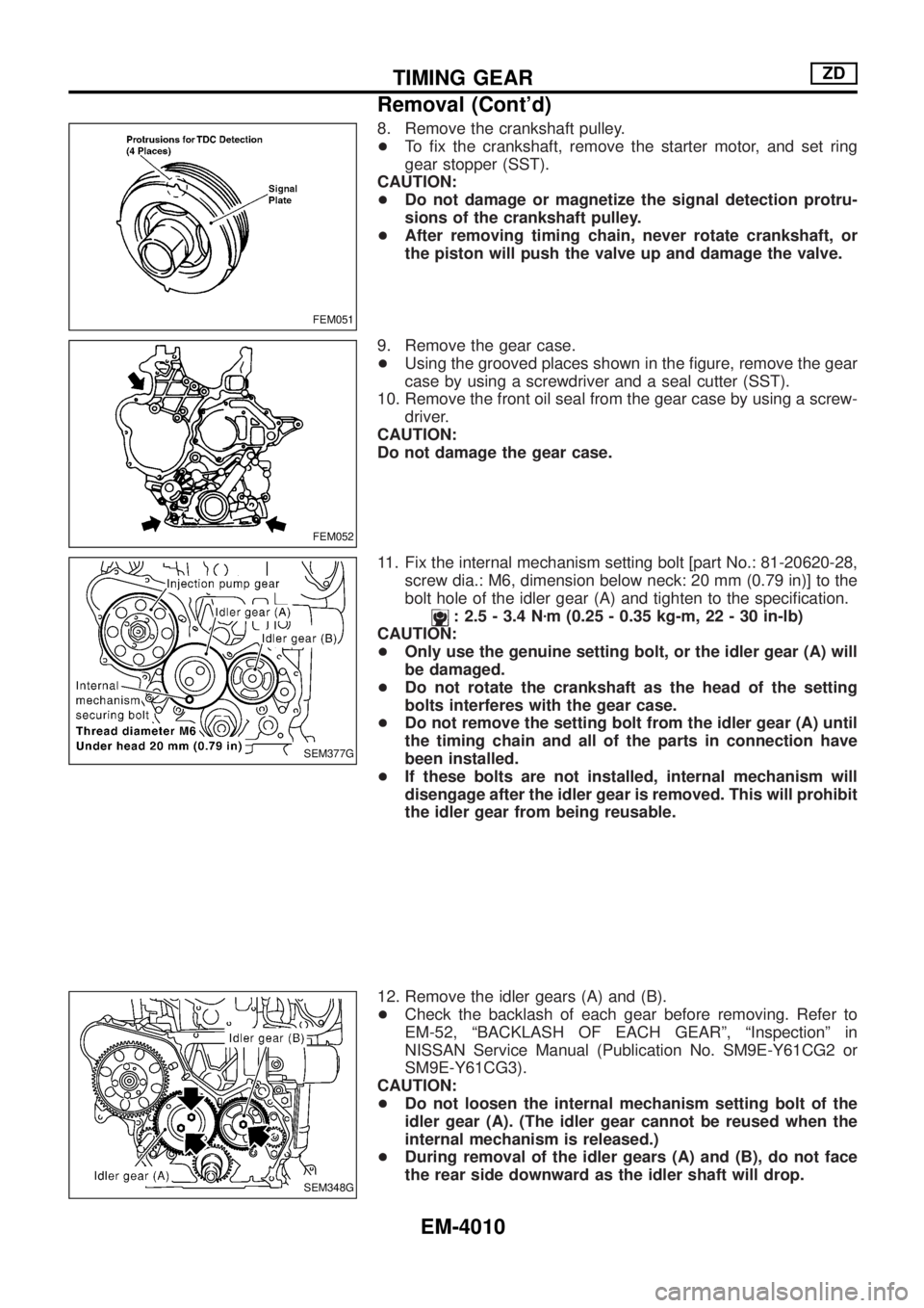
4. Remove the chain cover, timing chain and other parts in con-
nection.
Before removing timing chain, remove injection pump sprocket
with No. 1 cylinder being positioned at TDC. Refer to the ®g-
ure. Refer to ªTIMING CHAINº, EM-37 in NISSAN Service
Manual (Publication No. SM9E-Y61CG2 or SM9E-Y61CG3).
CAUTION:
After removing timing chain, never rotate crankshaft, or the
piston will push the valve up and damage the valve.
+Do not paint the match mark on the timing chain beforehand as
the No. 1 cylinder is set at the TDC during assembly.
5. Remove the TDC sensor.
CAUTION:
+Do not drop or hit the sensor.
+Store in a clean place free of iron ®lings, etc.
+Do not place near any magnetic equipment.
6. Remove the water pump and its stud bolts.
Refer to ªWATER PUMPº in LC section in NISSAN Service
Manual (Publication No. SM9E-Y61CG2 or SM9E-Y61CG3).
7. Remove the water inlet.
SEM376G
TIMING GEARZD
EM-4009
Page 452 of 579
8. Remove the crankshaft pulley.
+To ®x the crankshaft, remove the starter motor, and set ring
gear stopper (SST).
CAUTION:
+Do not damage or magnetize the signal detection protru-
sions of the crankshaft pulley.
+After removing timing chain, never rotate crankshaft, or
the piston will push the valve up and damage the valve.
9. Remove the gear case.
+Using the grooved places shown in the ®gure, remove the gear
case by using a screwdriver and a seal cutter (SST).
10. Remove the front oil seal from the gear case by using a screw-
driver.
CAUTION:
Do not damage the gear case.
11. Fix the internal mechanism setting bolt [part No.: 81-20620-28,
screw dia.: M6, dimension below neck: 20 mm (0.79 in)] to the
bolt hole of the idler gear (A) and tighten to the speci®cation.
: 2.5 - 3.4 Nzm (0.25 - 0.35 kg-m, 22 - 30 in-lb)
CAUTION:
+Only use the genuine setting bolt, or the idler gear (A) will
be damaged.
+Do not rotate the crankshaft as the head of the setting
bolts interferes with the gear case.
+Do not remove the setting bolt from the idler gear (A) until
the timing chain and all of the parts in connection have
been installed.
+If these bolts are not installed, internal mechanism will
disengage after the idler gear is removed. This will prohibit
the idler gear from being reusable.
12. Remove the idler gears (A) and (B).
+Check the backlash of each gear before removing. Refer to
EM-52, ªBACKLASH OF EACH GEARº, ªInspectionº in
NISSAN Service Manual (Publication No. SM9E-Y61CG2 or
SM9E-Y61CG3).
CAUTION:
+Do not loosen the internal mechanism setting bolt of the
idler gear (A). (The idler gear cannot be reused when the
internal mechanism is released.)
+During removal of the idler gears (A) and (B), do not face
the rear side downward as the idler shaft will drop.
FEM051
FEM052
SEM377G
SEM348G
TIMING GEARZD
Removal (Cont'd)
EM-4010
Page 456 of 579
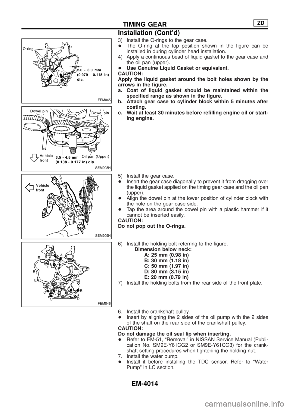
3) Install the O-rings to the gear case.
+The O-ring at the top position shown in the ®gure can be
installed in during cylinder head installation.
4) Apply a continuous bead of liquid gasket to the gear case and
the oil pan (upper).
+Use Genuine Liquid Gasket or equivalent.
CAUTION:
Apply the liquid gasket around the bolt holes shown by the
arrows in the ®gure.
a. Coat of liquid gasket should be maintained within the
speci®ed range as shown in the ®gure.
b. Attach gear case to cylinder block within 5 minutes after
coating.
c. Wait at least 30 minutes before re®lling engine oil or start-
ing engine.
5) Install the gear case.
+Insert the gear case diagonally to prevent it from dragging over
the liquid gasket applied on the timing gear case and the oil pan
(upper).
+Align the dowel pin at the lower position of cylinder block with
the hole on the gear case side.
+Tap the area around the dowel pin with a plastic hammer if it
cannot be inserted easily.
CAUTION:
Do not pop out the O-rings.
6) Install the holding bolt referring to the ®gure.
Dimension below neck:
A: 25 mm (0.98 in)
B: 30 mm (1.18 in)
C: 50 mm (1.97 in)
D: 80 mm (3.15 in)
E: 20 mm (0.79 in)
7) Install the holding bolts from the rear side of the front plate.
6. Install the crankshaft pulley.
+Insert by aligning the 2 sides of the oil pump with the 2 sides
of the shaft on the rear side of the crankshaft pulley.
CAUTION:
Do not damage the oil seal lip when inserting.
+Refer to EM-51, ªRemovalº in NISSAN Service Manual (Publi-
cation No. SM9E-Y61CG2 or SM9E-Y61CG3) for the crank-
shaft setting procedures when tightening the holding nut.
7. Install the water pump.
+Install it before installing the TDC sensor. Refer to ªWater
Pumpº in LC section.
FEM045
SEM208H
SEM209H
FEM046
TIMING GEARZD
Installation (Cont'd)
EM-4014
Page 457 of 579
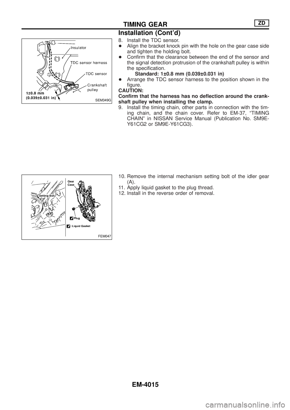
8. Install the TDC sensor.
+Align the bracket knock pin with the hole on the gear case side
and tighten the holding bolt.
+Con®rm that the clearance between the end of the sensor and
the signal detection protrusion of the crankshaft pulley is within
the speci®cation.
Standard: 1 0.8 mm (0.039 0.031 in)
+Arrange the TDC sensor harness to the position shown in the
®gure.
CAUTION:
Con®rm that the harness has no de¯ection around the crank-
shaft pulley when installing the clamp.
9. Install the timing chain, other parts in connection with the tim-
ing chain, and the chain cover. Refer to EM-37, ªTIMING
CHAINº in NISSAN Service Manual (Publication No. SM9E-
Y61CG2 or SM9E-Y61CG3).
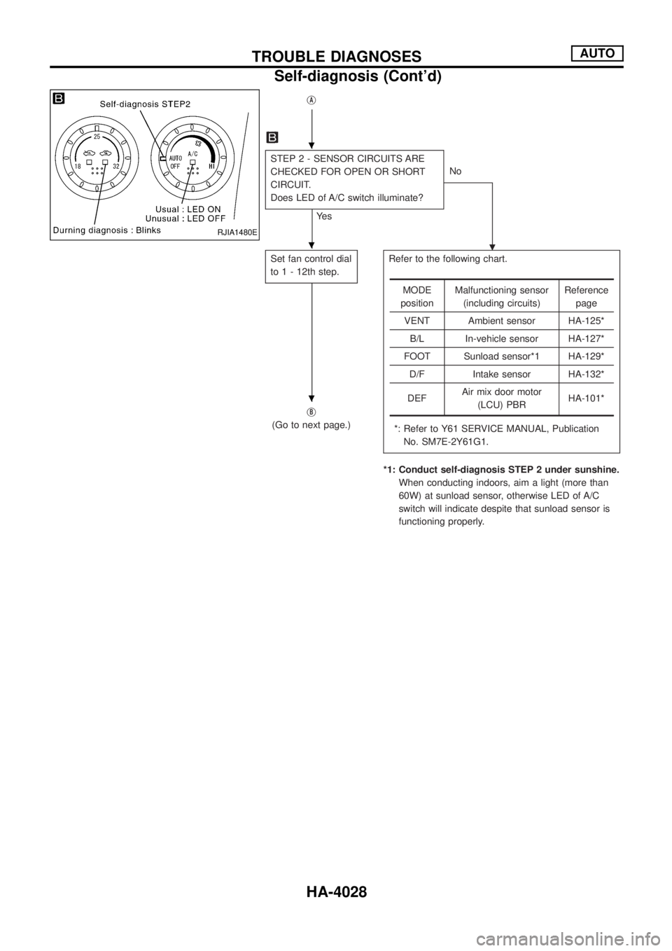
10. Remove the internal mechanism setting bolt of the idler gear
(A).
11. Apply liquid gasket to the plug thread.
12. Install in the reverse order of removal.
SEM349G
FEM047
TIMING GEARZD
Installation (Cont'd)
EM-4015
Page 459 of 579
Valve
VALVE CLEARANCE
Unit: mm (in)
ItemsCold*
Intake and exhaust0.30 - 0.40 (0.012 - 0.016)
*: Approximately 20ÉC (68ÉF)
AVAILABLE SHIMS
Thickness mm (in) Identi®cation mark
2.35 (0.0925) 2.35
2.40 (0.0945) 2.40
2.45 (0.0965) 2.45
2.50 (0.0984) 2.50
2.55 (0.1004) 2.55
2.60 (0.1024) 2.60
2.65 (0.1043) 2.65
2.70 (0.1063) 2.70
2.75 (0.1083) 2.75
2.80 (0.1102) 2.80
2.85 (0.1122) 2.85
2.90 (0.1142) 2.90
2.95 (0.1161) 2.95
3.00 (0.1181) 3.00
3.05 (0.1201) 3.05
JEM184G
VALVE LIFTER
Unit: mm (in)
Valve lifter outer diameter 34.450 - 34.465 (1.3563 - 1.3569)
Lifter guide inner diameter 34.495 - 34.515 (1.3581 - 1.3589)
Clearance between lifter and lifter guide 0.030 - 0.065 (0.0012 - 0.0026)
SERVICE DATA AND SPECIFICATIONS (SDS)ZD
EM-4017
Page 507 of 579
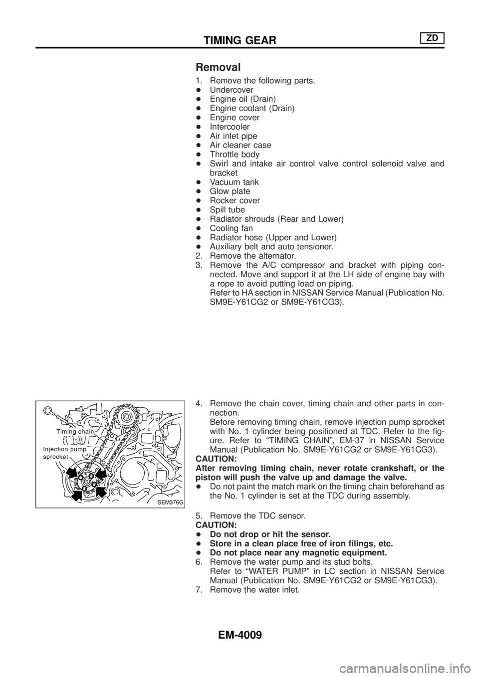
jA
STEP 2 - SENSOR CIRCUITS ARE
CHECKED FOR OPEN OR SHORT
CIRCUIT.
Does LED of A/C switch illuminate?
Ye sNo
.
Set fan control dial
to 1 - 12th step.Refer to the following chart.
*: Refer to Y61 SERVICE MANUAL, Publication
No. SM7E-2Y61G1.
*1: Conduct self-diagnosis STEP 2 under sunshine.
When conducting indoors, aim a light (more than
60W) at sunload sensor, otherwise LED of A/C
switch will indicate despite that sunload sensor is
functioning properly. j
B
(Go to next page.)
MODE
positionMalfunctioning sensor
(including circuits)Reference
page
VENT Ambient sensor HA-125*
B/L In-vehicle sensor HA-127*
FOOT Sunload sensor*1 HA-129*
D/F Intake sensor HA-132*
DEFAir mix door motor
(LCU) PBRHA-101*
RJIA1480E
.
.
.
TROUBLE DIAGNOSESAUTO
Self-diagnosis (Cont'd)
HA-4028
Page 511 of 579
Operational Check
The purpose of the operational check is to con®rm that the system
is as it should be. The systems which will be checked are the
blower, mode (discharge air), intake air, temperature decrease,
temperature increase and A/C switch.
CONDITIONS:
+Engine running and at normal operating temperature.
PROCEDURE:
1. Check blower
1) Turn fan control dial to 1st speed. Blower should operate at low
speed.
2) Turn fan control dial to 2nd speed, and continue checking
blower speed until all speeds are checked.
3) Leave blower on MAX speed.
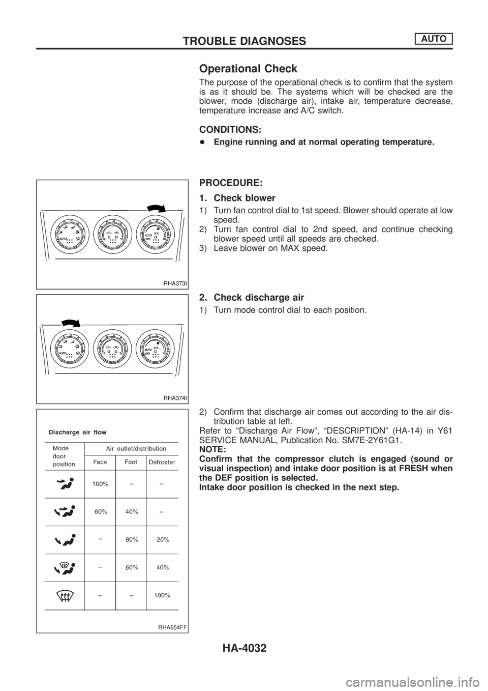
2. Check discharge air
1) Turn mode control dial to each position.
2) Con®rm that discharge air comes out according to the air dis-
tribution table at left.
Refer to ªDischarge Air Flowº, ªDESCRIPTIONº (HA-14) in Y61
SERVICE MANUAL, Publication No. SM7E-2Y61G1.
NOTE:
Con®rm that the compressor clutch is engaged (sound or
visual inspection) and intake door position is at FRESH when
the DEF position is selected.
Intake door position is checked in the next step.
RHA373I
RHA374I
RHA654FF
TROUBLE DIAGNOSESAUTO
HA-4032
Page 513 of 579
A/C System
TROUBLE DIAGNOSIS PROCEDURE FOR A/C SYSTEM
SYMPTOM:
+A/C system does not come on.
Inspection ¯ow
*1: HA-96 in Y61 SERVICE MANUAL,
Publication No. SM7E-2Y61G1*2: HA-4032
RHA379I
TROUBLE DIAGNOSESAUTO
HA-4034