Page 442 of 579

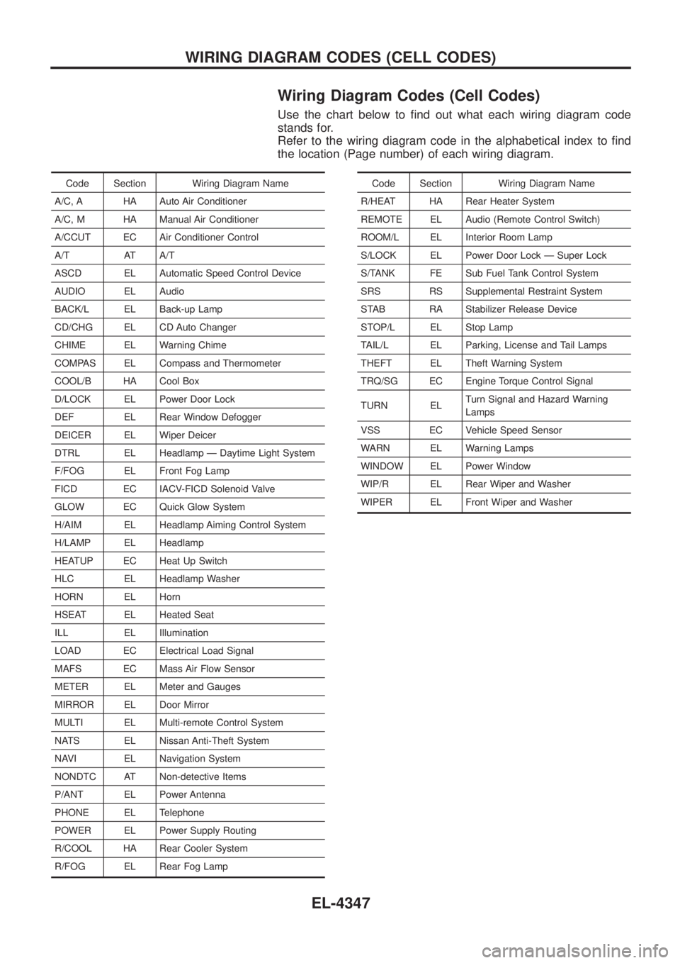
Wiring Diagram Codes (Cell Codes)
Use the chart below to ®nd out what each wiring diagram code
stands for.
Refer to the wiring diagram code in the alphabetical index to ®nd
the location (Page number) of each wiring diagram.
Code Section Wiring Diagram Name
A/C, A HA Auto Air Conditioner
A/C, M HA Manual Air Conditioner
A/CCUT EC Air Conditioner Control
A/T AT A/T
ASCD EL Automatic Speed Control Device
AUDIO EL Audio
BACK/L EL Back-up Lamp
CD/CHG EL CD Auto Changer
CHIME EL Warning Chime
COMPAS EL Compass and Thermometer
COOL/B HA Cool Box
D/LOCK EL Power Door Lock
DEF EL Rear Window Defogger
DEICER EL Wiper Deicer
DTRL EL Headlamp Ð Daytime Light System
F/FOG EL Front Fog Lamp
FICD EC IACV-FICD Solenoid Valve
GLOW EC Quick Glow System
H/AIM EL Headlamp Aiming Control System
H/LAMP EL Headlamp
HEATUP EC Heat Up Switch
HLC EL Headlamp Washer
HORN EL Horn
HSEAT EL Heated Seat
ILL EL Illumination
LOAD EC Electrical Load Signal
MAFS EC Mass Air Flow Sensor
METER EL Meter and Gauges
MIRROR EL Door Mirror
MULTI EL Multi-remote Control System
NATS EL Nissan Anti-Theft System
NAVI EL Navigation System
NONDTC AT Non-detective Items
P/ANT EL Power Antenna
PHONE EL Telephone
POWER EL Power Supply Routing
R/COOL HA Rear Cooler System
R/FOG EL Rear Fog LampCode Section Wiring Diagram Name
R/HEAT HA Rear Heater System
REMOTE EL Audio (Remote Control Switch)
ROOM/L EL Interior Room Lamp
S/LOCK EL Power Door Lock Ð Super Lock
S/TANK FE Sub Fuel Tank Control System
SRS RS Supplemental Restraint System
STAB RA Stabilizer Release Device
STOP/L EL Stop Lamp
TAIL/L EL Parking, License and Tail Lamps
THEFT EL Theft Warning System
TRQ/SG EC Engine Torque Control Signal
TURN EL Turn Signal and Hazard Warning
Lamps
VSS EC Vehicle Speed Sensor
WARN EL Warning Lamps
WINDOW EL Power Window
WIP/R EL Rear Wiper and Washer
WIPER EL Front Wiper and Washer
WIRING DIAGRAM CODES (CELL CODES)
EL-4347
Page 451 of 579

Removal
1. Remove the following parts.
+Undercover
+Engine oil (Drain)
+Engine coolant (Drain)
+Engine cover
+Intercooler
+Air inlet pipe
+Air cleaner case
+Throttle body
+Swirl and intake air control valve control solenoid valve and
bracket
+Vacuum tank
+Glow plate
+Rocker cover
+Spill tube
+Radiator shrouds (Rear and Lower)
+Cooling fan
+Radiator hose (Upper and Lower)
+Auxiliary belt and auto tensioner.
2. Remove the alternator.
3. Remove the A/C compressor and bracket with piping con-
nected. Move and support it at the LH side of engine bay with
a rope to avoid putting load on piping.
Refer to HA section in NISSAN Service Manual (Publication No.
SM9E-Y61CG2 or SM9E-Y61CG3).
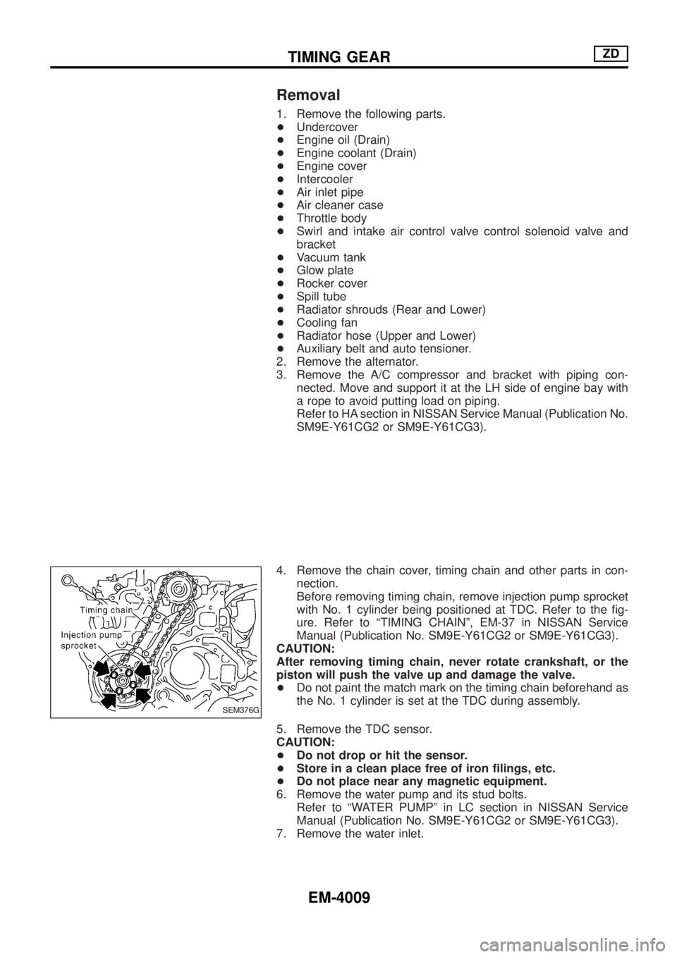
4. Remove the chain cover, timing chain and other parts in con-
nection.
Before removing timing chain, remove injection pump sprocket
with No. 1 cylinder being positioned at TDC. Refer to the ®g-
ure. Refer to ªTIMING CHAINº, EM-37 in NISSAN Service
Manual (Publication No. SM9E-Y61CG2 or SM9E-Y61CG3).
CAUTION:
After removing timing chain, never rotate crankshaft, or the
piston will push the valve up and damage the valve.
+Do not paint the match mark on the timing chain beforehand as
the No. 1 cylinder is set at the TDC during assembly.
5. Remove the TDC sensor.
CAUTION:
+Do not drop or hit the sensor.
+Store in a clean place free of iron ®lings, etc.
+Do not place near any magnetic equipment.
6. Remove the water pump and its stud bolts.
Refer to ªWATER PUMPº in LC section in NISSAN Service
Manual (Publication No. SM9E-Y61CG2 or SM9E-Y61CG3).
7. Remove the water inlet.
SEM376G
TIMING GEARZD
EM-4009
Page 460 of 579
ACCELERATORCONTROL,FUEL&
EXHAUST SYSTEMS
SECTION
FE
MODIFICATION NOTICE:
+ Wiring diagram of sub fuel tank control system has been modi®ed.
CONTENTS
TROUBLE DIAGNOSES ...........................................4002
Self-diagnosis for Sub Fuel Tank Control Module.4002
Circuit Diagram Ð S/TANK Ð ..............................4003 Wiring Diagram Ð S/TANK Ð ..............................4004
EXHAUST SYSTEM ..................................................4008
FE-4001
Page 461 of 579

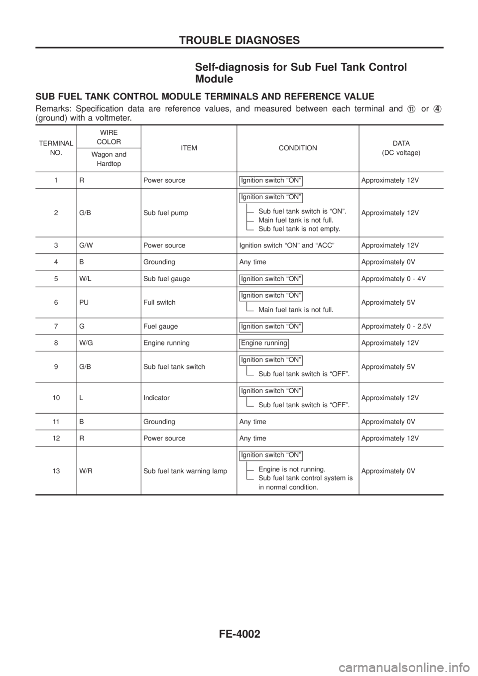
Self-diagnosis for Sub Fuel Tank Control
Module
SUB FUEL TANK CONTROL MODULE TERMINALS AND REFERENCE VALUE
Remarks: Speci®cation data are reference values, and measured between each terminal andj11orj4
(ground) with a voltmeter.
TERMINAL
NO.WIRE
COLOR
ITEM CONDITIONDATA
(DC voltage)
Wagon and
Hardtop
1 R Power source Ignition switch ªONº
Approximately 12V
2 G/B Sub fuel pumpIgnition switch ªONº
Sub fuel tank switch is ªONº.
Main fuel tank is not full.
Sub fuel tank is not empty.Approximately 12V
3 G/W Power source Ignition switch ªONº and ªACCº Approximately 12V
4 B Grounding Any time Approximately 0V
5 W/L Sub fuel gauge Ignition switch ªONº
Approximately0-4V
6 PU Full switchIgnition switch ªONº
Main fuel tank is not full.Approximately 5V
7 G Fuel gauge Ignition switch ªONº
Approximately 0 - 2.5V
8 W/G Engine running Engine running
Approximately 12V
9 G/B Sub fuel tank switchIgnition switch ªONº
Sub fuel tank switch is ªOFFº.Approximately 5V
10 L IndicatorIgnition switch ªONº
Sub fuel tank switch is ªOFFº.Approximately 12V
11 B Grounding Any time Approximately 0V
12 R Power source Any time Approximately 12V
13 W/R Sub fuel tank warning lampIgnition switch ªONº
Engine is not running.
Sub fuel tank control system is
in normal condition.Approximately 0V
TROUBLE DIAGNOSES
FE-4002
Page 462 of 579
Circuit Diagram Ð S/TANK Ð
WAGON AND HARDTOP MODELS
TFE061M
TROUBLE DIAGNOSES
FE-4003
Page 463 of 579
Wiring Diagram Ð S/TANK Ð
WAGON AND HARDTOP MODELS
TFE051M
TROUBLE DIAGNOSES
FE-4004
Page 464 of 579
WAGON AND HARDTOP MODELS
TFE062M
TROUBLE DIAGNOSES
Wiring Diagram Ð S/TANK Ð (Cont'd)
FE-4005
Page 465 of 579
WAGON AND HARDTOP MODELS (LHD)
TFE063M
TROUBLE DIAGNOSES
Wiring Diagram Ð S/TANK Ð (Cont'd)
FE-4006