2004 NISSAN PATROL EL Start
[x] Cancel search: EL StartPage 2 of 579
FOREWORD
This manual contains maintenance and repair procedures for NISSAN
PATROL,modelY61 series.
In order to assure your safety and the efficient functioning of the vehicle,
this manual should be read thoroughly. It is especially important that the
PRECAUTIONS in the GI section be completely understood before starting
any repair task.
All information in this manual is based on the latest product information
at the time of publication. The right is reserved to make changes in speci-
®cations and methods at any time without notice.
IMPORTANT SAFETY NOTICE
The proper performance of service is essential for both the safety of the
technician and the efficient functioning of the vehicle.
The service methods in this Service Manual are described in such a man-
ner that the service may be performed safely and accurately.
Service varies with the procedures used, the skills of the technician and the
tools and parts available. Accordingly, anyone using service procedures,
tools or parts which are not speci®cally recommended by NISSAN must
®rst completely satisfy himself that neither his safety nor the vehicle's
safety will be jeopardized by the service method selected.
NISSAN EUROPE S.A.S.
Service Engineering SectionParis, France
Page 44 of 579
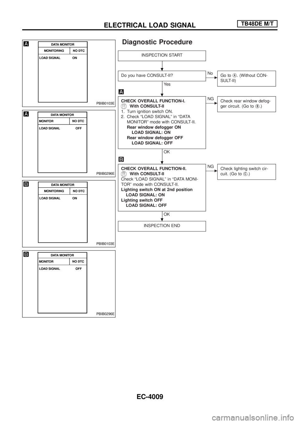
Diagnostic Procedure
INSPECTION START
Do you have CONSULT-II?
Ye s
cNo
Go tojA. (Without CON-
SULT-II)
CHECK OVERALL FUNCTION-I.
With CONSULT-II
1. Turn ignition switch ON.
2. Check ªLOAD SIGNALº in ªDATA
MONITORº mode with CONSULT-II.
Rear window defogger ON
LOAD SIGNAL: ON
Rear window defogger OFF
LOAD SIGNAL: OFF
OK
cNG
Check rear window defog-
ger circuit. (Go toj
B.)
CHECK OVERALL FUNCTION-II.
With CONSULT-II
Check ªLOAD SIGNALº in ªDATA MONI-
TORº mode with CONSULT-II.
Lighting switch ON at 2nd position
LOAD SIGNAL: ON
Lighting switch OFF
LOAD SIGNAL: OFF
OK
cNG
Check lighting switch cir-
cuit. (Go toj
C.)
INSPECTION END
PBIB0103E
PBIB0296E
PBIB0103E
PBIB0296E
.
.
.
.
ELECTRICAL LOAD SIGNALTB48DE M/T
EC-4009
Page 46 of 579
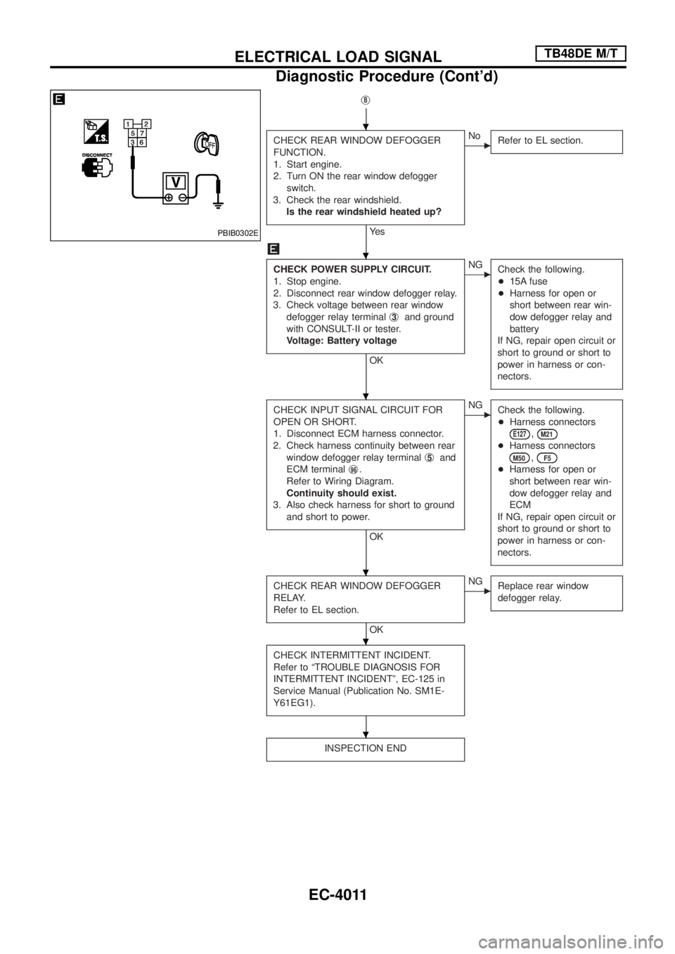
jB
CHECK REAR WINDOW DEFOGGER
FUNCTION.
1. Start engine.
2. Turn ON the rear window defogger
switch.
3. Check the rear windshield.
Is the rear windshield heated up?
Ye s
cNo
Refer to EL section.
CHECK POWER SUPPLY CIRCUIT.
1. Stop engine.
2. Disconnect rear window defogger relay.
3. Check voltage between rear window
defogger relay terminalj
3and ground
with CONSULT-II or tester.
Voltage: Battery voltage
OK
cNG
Check the following.
+15A fuse
+Harness for open or
short between rear win-
dow defogger relay and
battery
If NG, repair open circuit or
short to ground or short to
power in harness or con-
nectors.
CHECK INPUT SIGNAL CIRCUIT FOR
OPEN OR SHORT.
1. Disconnect ECM harness connector.
2. Check harness continuity between rear
window defogger relay terminalj
5and
ECM terminalj
96.
Refer to Wiring Diagram.
Continuity should exist.
3. Also check harness for short to ground
and short to power.
OK
cNG
Check the following.
+Harness connectors
E127,M21
+Harness connectors
M50,F5
+Harness for open or
short between rear win-
dow defogger relay and
ECM
If NG, repair open circuit or
short to ground or short to
power in harness or con-
nectors.
CHECK REAR WINDOW DEFOGGER
RELAY.
Refer to EL section.
OK
cNG
Replace rear window
defogger relay.
CHECK INTERMITTENT INCIDENT.
Refer to ªTROUBLE DIAGNOSIS FOR
INTERMITTENT INCIDENTº, EC-125 in
Service Manual (Publication No. SM1E-
Y61EG1).
INSPECTION END
PBIB0302E
.
.
.
.
.
.
ELECTRICAL LOAD SIGNALTB48DE M/T
Diagnostic Procedure (Cont'd)
EC-4011
Page 54 of 579
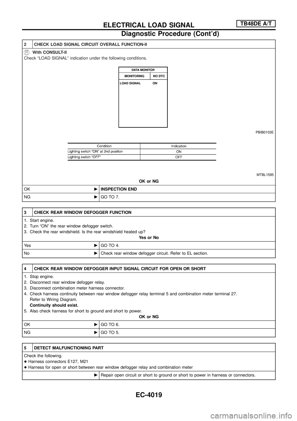
2 CHECK LOAD SIGNAL CIRCUIT OVERALL FUNCTION-II
With CONSULT-II
Check ªLOAD SIGNALº indication under the following conditions.
PBIB0103E
MTBL1595
OK or NG
OKcINSPECTION END
NGcGO TO 7.
3 CHECK REAR WINDOW DEFOGGER FUNCTION
1. Start engine.
2. Turn ªONº the rear window defogger switch.
3. Check the rear windshield. Is the rear windshield heated up?
YesorNo
Ye scGO TO 4.
NocCheck rear window defogger circuit. Refer to EL section.
4 CHECK REAR WINDOW DEFOGGER INPUT SIGNAL CIRCUIT FOR OPEN OR SHORT
1. Stop engine.
2. Disconnect rear window defogger relay.
3. Disconnect combination meter harness connector.
4. Check harness continuity between rear window defogger relay terminal 5 and combination meter terminal 27.
Refer to Wiring Diagram.
Continuity should exist.
5. Also check harness for short to ground and short to power.
OK or NG
OKcGO TO 6.
NGcGO TO 5.
5 DETECT MALFUNCTIONING PART
Check the following.
+Harness connectors E127, M21
+Harness for open or short between rear window defogger relay and combination meter
cRepair open circuit or short to ground or short to power in harness or connectors.
ELECTRICAL LOAD SIGNALTB48DE A/T
Diagnostic Procedure (Cont'd)
EC-4019
Page 55 of 579
6 CHECK COMBINATION METER
Refer to EL section.
OK or NG
OKcGO TO 11.
NGcReplace combination meter.
7 CHECK HEADLAMP FUNCTION
1. Start engine.
2. Lighting switch ªONº at 2nd position.
3. Check that headlamp high beams are illuminated.
OK or NG
OKcGO TO 8.
NGcCheck headlamp circuit. Refer to EL section.
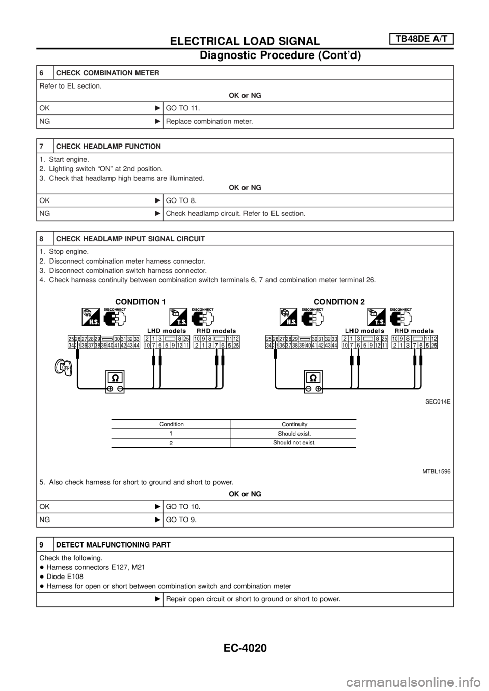
8 CHECK HEADLAMP INPUT SIGNAL CIRCUIT
1. Stop engine.
2. Disconnect combination meter harness connector.
3. Disconnect combination switch harness connector.
4. Check harness continuity between combination switch terminals 6, 7 and combination meter terminal 26.
SEC014E
MTBL1596
5. Also check harness for short to ground and short to power.
OK or NG
OKcGO TO 10.
NGcGO TO 9.
9 DETECT MALFUNCTIONING PART
Check the following.
+Harness connectors E127, M21
+Diode E108
+Harness for open or short between combination switch and combination meter
cRepair open circuit or short to ground or short to power.
ELECTRICAL LOAD SIGNALTB48DE A/T
Diagnostic Procedure (Cont'd)
EC-4020
Page 63 of 579
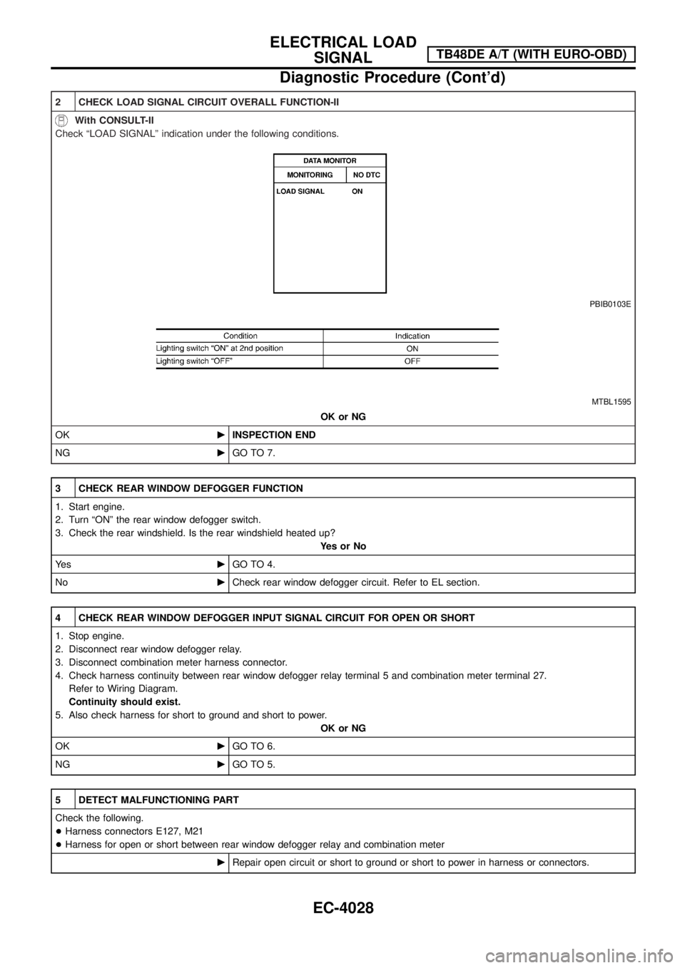
2 CHECK LOAD SIGNAL CIRCUIT OVERALL FUNCTION-II
With CONSULT-II
Check ªLOAD SIGNALº indication under the following conditions.
PBIB0103E
MTBL1595
OK or NG
OKcINSPECTION END
NGcGO TO 7.
3 CHECK REAR WINDOW DEFOGGER FUNCTION
1. Start engine.
2. Turn ªONº the rear window defogger switch.
3. Check the rear windshield. Is the rear windshield heated up?
YesorNo
Ye scGO TO 4.
NocCheck rear window defogger circuit. Refer to EL section.
4 CHECK REAR WINDOW DEFOGGER INPUT SIGNAL CIRCUIT FOR OPEN OR SHORT
1. Stop engine.
2. Disconnect rear window defogger relay.
3. Disconnect combination meter harness connector.
4. Check harness continuity between rear window defogger relay terminal 5 and combination meter terminal 27.
Refer to Wiring Diagram.
Continuity should exist.
5. Also check harness for short to ground and short to power.
OK or NG
OKcGO TO 6.
NGcGO TO 5.
5 DETECT MALFUNCTIONING PART
Check the following.
+Harness connectors E127, M21
+Harness for open or short between rear window defogger relay and combination meter
cRepair open circuit or short to ground or short to power in harness or connectors.
ELECTRICAL LOAD
SIGNALTB48DE A/T (WITH EURO-OBD)
Diagnostic Procedure (Cont'd)
EC-4028
Page 64 of 579
6 CHECK COMBINATION METER
Refer to EL section.
OK or NG
OKcGO TO 11.
NGcReplace combination meter.
7 CHECK HEADLAMP FUNCTION
1. Start engine.
2. Lighting switch ªONº at 2nd position.
3. Check that headlamp high beams are illuminated.
OK or NG
OKcGO TO 8.
NGcCheck headlamp circuit. Refer to EL section.
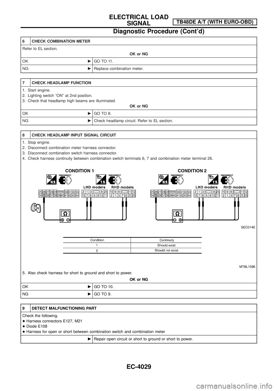
8 CHECK HEADLAMP INPUT SIGNAL CIRCUIT
1. Stop engine.
2. Disconnect combination meter harness connector.
3. Disconnect combination switch harness connector.
4. Check harness continuity between combination switch terminals 6, 7 and combination meter terminal 26.
SEC014E
MTBL1596
5. Also check harness for short to ground and short to power.
OK or NG
OKcGO TO 10.
NGcGO TO 9.
9 DETECT MALFUNCTIONING PART
Check the following.
+Harness connectors E127, M21
+Diode E108
+Harness for open or short between combination switch and combination meter
cRepair open circuit or short to ground or short to power.
ELECTRICAL LOAD
SIGNALTB48DE A/T (WITH EURO-OBD)
Diagnostic Procedure (Cont'd)
EC-4029
Page 73 of 579
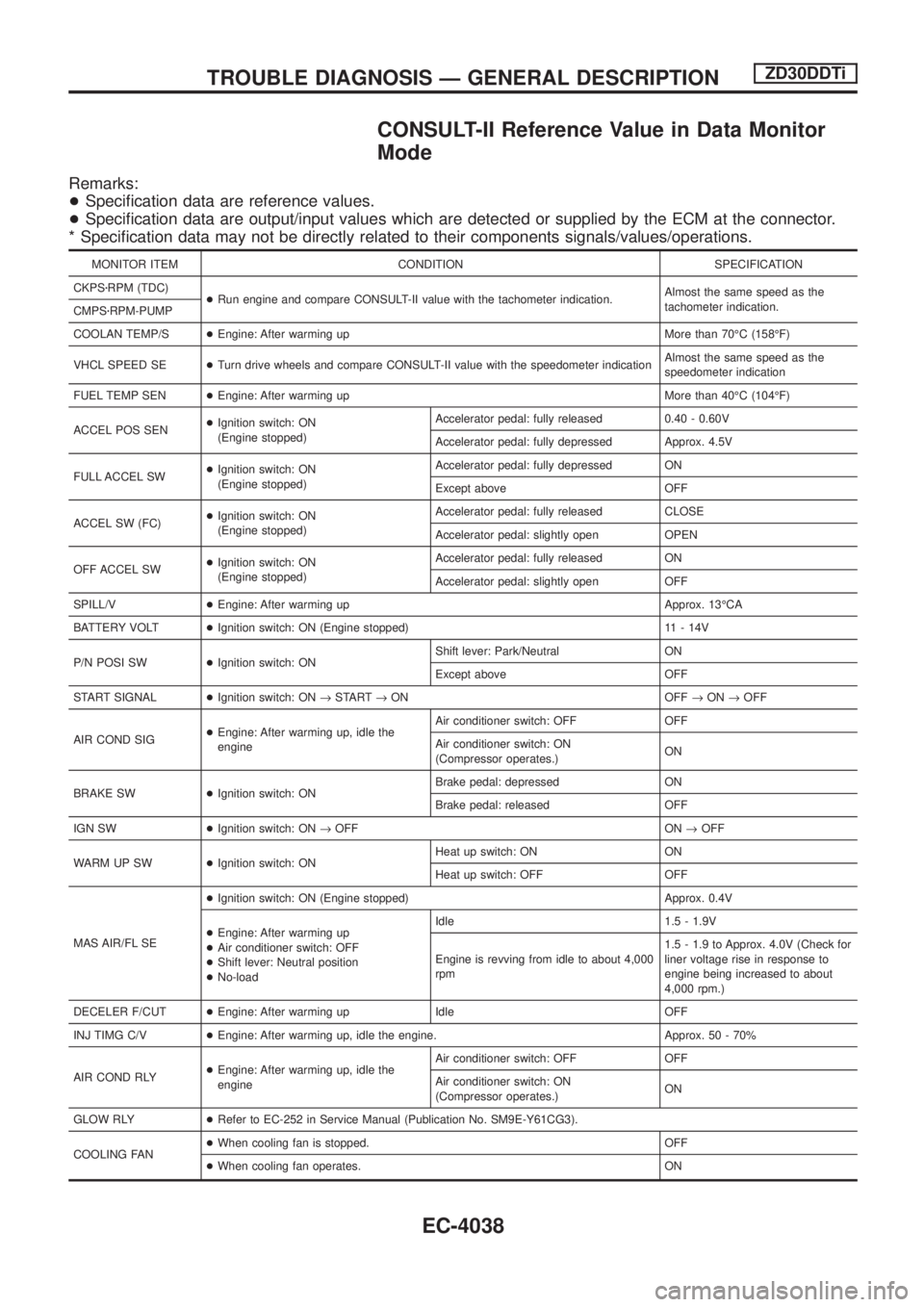
CONSULT-II Reference Value in Data Monitor
Mode
Remarks:
+Speci®cation data are reference values.
+Speci®cation data are output/input values which are detected or supplied by the ECM at the connector.
* Speci®cation data may not be directly related to their components signals/values/operations.
MONITOR ITEM CONDITION SPECIFICATION
CKPSzRPM (TDC)
+Run engine and compare CONSULT-II value with the tachometer indication.Almost the same speed as the
tachometer indication.
CMPSzRPM-PUMP
COOLAN TEMP/S+Engine: After warming up More than 70ÉC (158ÉF)
VHCL SPEED SE+Turn drive wheels and compare CONSULT-II value with the speedometer indicationAlmost the same speed as the
speedometer indication
FUEL TEMP SEN+Engine: After warming up More than 40ÉC (104ÉF)
ACCEL POS SEN+Ignition switch: ON
(Engine stopped)Accelerator pedal: fully released 0.40 - 0.60V
Accelerator pedal: fully depressed Approx. 4.5V
FULL ACCEL SW+Ignition switch: ON
(Engine stopped)Accelerator pedal: fully depressed ON
Except above OFF
ACCEL SW (FC)+Ignition switch: ON
(Engine stopped)Accelerator pedal: fully released CLOSE
Accelerator pedal: slightly open OPEN
OFF ACCEL SW+Ignition switch: ON
(Engine stopped)Accelerator pedal: fully released ON
Accelerator pedal: slightly open OFF
SPILL/V+Engine: After warming up Approx. 13ÉCA
BATTERY VOLT+Ignition switch: ON (Engine stopped) 11 - 14V
P/N POSI SW+Ignition switch: ONShift lever: Park/Neutral ON
Except above OFF
START SIGNAL+Ignition switch: ON®START®ON OFF®ON®OFF
AIR COND SIG+Engine: After warming up, idle the
engineAir conditioner switch: OFF OFF
Air conditioner switch: ON
(Compressor operates.)ON
BRAKE SW+Ignition switch: ONBrake pedal: depressed ON
Brake pedal: released OFF
IGN SW+Ignition switch: ON®OFF ON®OFF
WARM UP SW+Ignition switch: ONHeat up switch: ON ON
Heat up switch: OFF OFF
MAS AIR/FL SE+Ignition switch: ON (Engine stopped) Approx. 0.4V
+Engine: After warming up
+Air conditioner switch: OFF
+Shift lever: Neutral position
+No-loadIdle 1.5 - 1.9V
Engine is revving from idle to about 4,000
rpm1.5 - 1.9 to Approx. 4.0V (Check for
liner voltage rise in response to
engine being increased to about
4,000 rpm.)
DECELER F/CUT+Engine: After warming up Idle OFF
INJ TIMG C/V+Engine: After warming up, idle the engine. Approx. 50 - 70%
AIR COND RLY+Engine: After warming up, idle the
engineAir conditioner switch: OFF OFF
Air conditioner switch: ON
(Compressor operates.)ON
GLOW RLY+Refer to EC-252 in Service Manual (Publication No. SM9E-Y61CG3).
COOLING FAN+When cooling fan is stopped. OFF
+When cooling fan operates. ON
TROUBLE DIAGNOSIS Ð GENERAL DESCRIPTIONZD30DDTi
EC-4038