Page 456 of 579

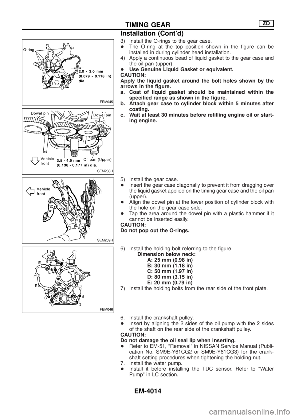
3) Install the O-rings to the gear case.
+The O-ring at the top position shown in the ®gure can be
installed in during cylinder head installation.
4) Apply a continuous bead of liquid gasket to the gear case and
the oil pan (upper).
+Use Genuine Liquid Gasket or equivalent.
CAUTION:
Apply the liquid gasket around the bolt holes shown by the
arrows in the ®gure.
a. Coat of liquid gasket should be maintained within the
speci®ed range as shown in the ®gure.
b. Attach gear case to cylinder block within 5 minutes after
coating.
c. Wait at least 30 minutes before re®lling engine oil or start-
ing engine.
5) Install the gear case.
+Insert the gear case diagonally to prevent it from dragging over
the liquid gasket applied on the timing gear case and the oil pan
(upper).
+Align the dowel pin at the lower position of cylinder block with
the hole on the gear case side.
+Tap the area around the dowel pin with a plastic hammer if it
cannot be inserted easily.
CAUTION:
Do not pop out the O-rings.
6) Install the holding bolt referring to the ®gure.
Dimension below neck:
A: 25 mm (0.98 in)
B: 30 mm (1.18 in)
C: 50 mm (1.97 in)
D: 80 mm (3.15 in)
E: 20 mm (0.79 in)
7) Install the holding bolts from the rear side of the front plate.
6. Install the crankshaft pulley.
+Insert by aligning the 2 sides of the oil pump with the 2 sides
of the shaft on the rear side of the crankshaft pulley.
CAUTION:
Do not damage the oil seal lip when inserting.
+Refer to EM-51, ªRemovalº in NISSAN Service Manual (Publi-
cation No. SM9E-Y61CG2 or SM9E-Y61CG3) for the crank-
shaft setting procedures when tightening the holding nut.
7. Install the water pump.
+Install it before installing the TDC sensor. Refer to ªWater
Pumpº in LC section.
FEM045
SEM208H
SEM209H
FEM046
TIMING GEARZD
Installation (Cont'd)
EM-4014
Page 504 of 579

Self-diagnosis
INTRODUCTION AND GENERAL DESCRIPTION
The self-diagnostic system diagnoses sensors, door motors, blower motor, etc. by system line.
Self-diagnosis is step-1 to 7. There are two ways of changing method during self-diagnosis.
+Switching to self-diagnosis step-1 to 4.
Shifting from usual control to the self-diagnostic system is accomplished by starting the engine (turning
the ignition switch from OFF to ON) and pressing A/C switch for at least 5 seconds. The A/C switch must
be pressed within 10 seconds after starting the engine (ignition switch is turned ON). This system will be
canceled by either pressing intake switch or turning the ignition switch OFF. Shifting from one step to
another is accomplished be means of turning fan control dial, as required.
+Switching to self-diagnosis step-5 to 7 (Auxiliary mechanism).
Shifting from usual control to the self-diagnostic system is accomplished by starting the engine (turning
the ignition switch from OFF to ON) and pressing intake switch for at least 5 seconds. The intake switch
must be pressed within 10 seconds after starting the engine (ignition switch is turned ON). This system
will be canceled by either pressing A/C switch or turning the ignition switch OFF. Shifting from one step
to another is accomplished by means of turning fan control dial, as required.
TROUBLE DIAGNOSESAUTO
HA-4025
Page 506 of 579
STEP-BY-STEP PROCEDURE
Set mode control dial to AUTO.
Set temperature control dial to 25ÉC.
Set fan control dial to OFF.
Turn ignition switch ON.
Set in self-diagnostic mode. Within 10 sec-
onds after starting engine (ignition switch is
turned ªONº.), press A/C switch for at least
5 seconds.
STEP 1 - LEDs ARE CHECKED.
Do all LEDs illuminate?
Ye s
cNo
Malfunctioning A/C switch
or LED.
Replace A/C auto amp.
Set fan control dial to AUTO.
Advance to self-diagnosis STEP 2?
Ye s
cNo
Malfunctioning fan control
dial.
Replace A/C auto amp.
Set fan control dial to OFF.
Return to self-diagnosis STEP 1?
Ye s
cNo
Malfunctioning fan control
dial.
Replace A/C auto amp.
Set fan control dial to AUTO.
jA
(Go to next page.)
RHA409I
.
.
.
.
.
.
.
.
.
.
.
TROUBLE DIAGNOSESAUTO
Self-diagnosis (Cont'd)
HA-4027
Page 510 of 579

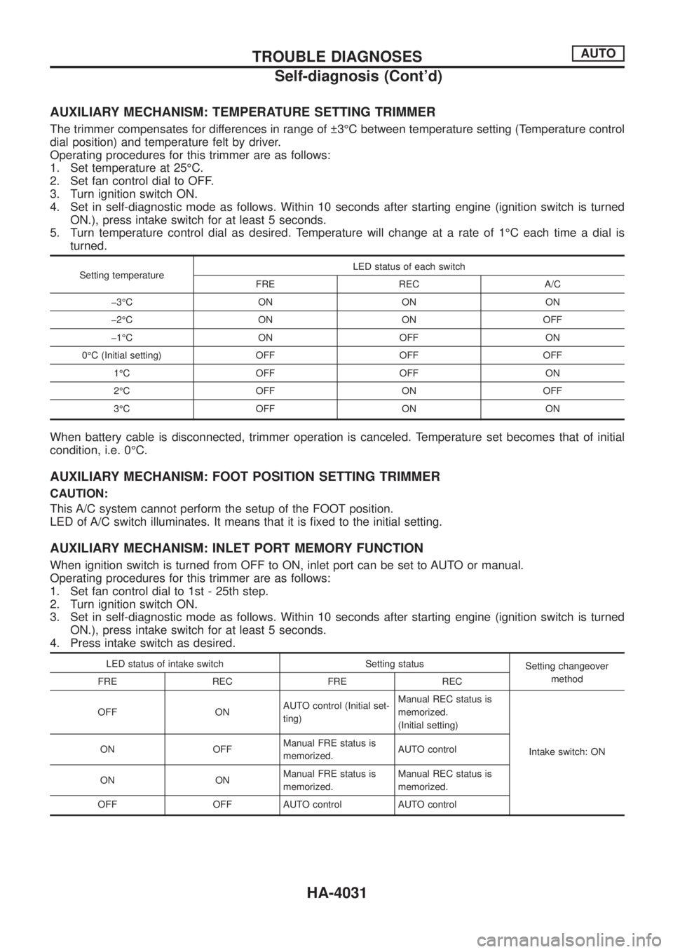
AUXILIARY MECHANISM: TEMPERATURE SETTING TRIMMER
The trimmer compensates for differences in range of 3ÉC between temperature setting (Temperature control
dial position) and temperature felt by driver.
Operating procedures for this trimmer are as follows:
1. Set temperature at 25ÉC.
2. Set fan control dial to OFF.
3. Turn ignition switch ON.
4. Set in self-diagnostic mode as follows. Within 10 seconds after starting engine (ignition switch is turned
ON.), press intake switch for at least 5 seconds.
5. Turn temperature control dial as desired. Temperature will change at a rate of 1ÉC each time a dial is
turned.
Setting temperatureLED status of each switch
FRE REC A/C
þ3ÉC ON ON ON
þ2ÉC ON ON OFF
þ1ÉC ON OFF ON
0ÉC (Initial setting) OFF OFF OFF
1ÉC OFF OFF ON
2ÉC OFF ON OFF
3ÉC OFF ON ON
When battery cable is disconnected, trimmer operation is canceled. Temperature set becomes that of initial
condition, i.e. 0ÉC.
AUXILIARY MECHANISM: FOOT POSITION SETTING TRIMMER
CAUTION:
This A/C system cannot perform the setup of the FOOT position.
LED of A/C switch illuminates. It means that it is ®xed to the initial setting.
AUXILIARY MECHANISM: INLET PORT MEMORY FUNCTION
When ignition switch is turned from OFF to ON, inlet port can be set to AUTO or manual.
Operating procedures for this trimmer are as follows:
1. Set fan control dial to 1st - 25th step.
2. Turn ignition switch ON.
3. Set in self-diagnostic mode as follows. Within 10 seconds after starting engine (ignition switch is turned
ON.), press intake switch for at least 5 seconds.
4. Press intake switch as desired.
LED status of intake switch Setting status
Setting changeover
method
FRE REC FRE REC
OFF ONAUTO control (Initial set-
ting)Manual REC status is
memorized.
(Initial setting)
Intake switch: ON ON OFFManual FRE status is
memorized.AUTO control
ON ONManual FRE status is
memorized.Manual REC status is
memorized.
OFF OFF AUTO control AUTO control
TROUBLE DIAGNOSESAUTO
Self-diagnosis (Cont'd)
HA-4031
Page 517 of 579
Blower Motor
TROUBLE DIAGNOSIS PROCEDURE FOR BLOWER MOTOR
SYMPTOM:
+Blower motor operation is malfunctioning.
+Blower motor operation is malfunctioning under out of starting fan speed control.
Inspection ¯ow
*1: HA-4027
*2: HA-4028
*3: HA-4030
*4: HA-111**5: HA-125*
*6: HA-127*
*7: HA-129**8: HA-132*
*9: HA-91*
*10: HA-4032
*: Refer to Y61 SERVICE MANUAL, Publication No. SM7E-2Y61G1.
RHA383I
TROUBLE DIAGNOSESAUTO
HA-4038