Page 16 of 579

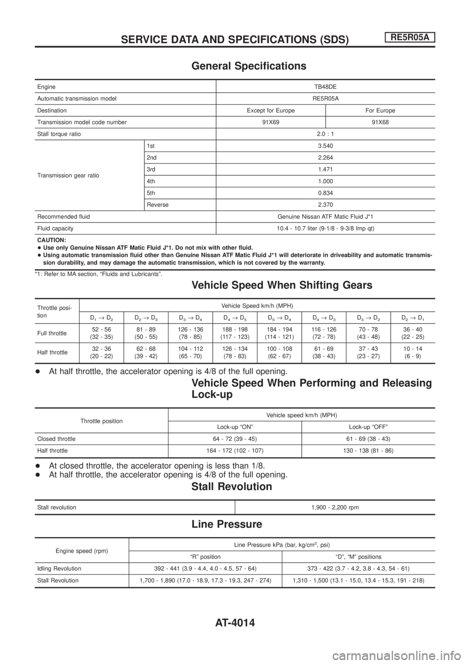
General Speci®cations
EngineTB48DE
Automatic transmission modelRE5R05A
Destination Except for Europe For Europe
Transmission model code number 91X69 91X68
Stall torque ratio2.0:1
Transmission gear ratio1st 3.540
2nd 2.264
3rd 1.471
4th 1.000
5th 0.834
Reverse 2.370
Recommended ¯uid Genuine Nissan ATF Matic Fluid J*1
Fluid capacity10.4 - 10.7 liter (9-1/8 - 9-3/8 Imp qt)
CAUTION:
+Use only Genuine Nissan ATF Matic Fluid J*1. Do not mix with other ¯uid.
+Using automatic transmission ¯uid other than Genuine Nissan ATF Matic Fluid J*1 will deteriorate in driveability and automatic transmis-
sion durability, and may damage the automatic transmission, which is not covered by the warranty.
*1: Refer to MA section, ªFluids and Lubricantsº.
Vehicle Speed When Shifting Gears
Throttle posi-
tionVehicle Speed km/h (MPH)
D
1®D2D2®D3D3®D4D4®D5D5®D4D4®D3D3®D2D2®D1
Full throttle52-56
(32 - 35)81-89
(50 - 55)126 - 136
(78 - 85)188 - 198
(117 - 123)184 - 194
(114 - 121)116 - 126
(72 - 78)70-78
(43 - 48)36-40
(22 - 25)
Half throttle32-36
(20 - 22)62-68
(39 - 42)104 - 112
(65 - 70)126 - 134
(78 - 83)100 - 108
(62 - 67)61-69
(38 - 43)37-43
(23 - 27)10-14
(6-9)
+At half throttle, the accelerator opening is 4/8 of the full opening.
Vehicle Speed When Performing and Releasing
Lock-up
Throttle positionVehicle speed km/h (MPH)
Lock-up ªONº Lock-up ªOFFº
Closed throttle 64 - 72 (39 - 45) 61 - 69 (38 - 43)
Half throttle 164 - 172 (102 - 107) 130 - 138 (81 - 86)
+At closed throttle, the accelerator opening is less than 1/8.
+At half throttle, the accelerator opening is 4/8 of the full opening.
Stall Revolution
Stall revolution1,900 - 2,200 rpm
Line Pressure
Engine speed (rpm)Line Pressure kPa (bar, kg/cm
2, psi)
ªRº position ªDº, ªMº positions
Idling Revolution 392 - 441 (3.9 - 4.4, 4.0 - 4.5, 57 - 64) 373 - 422 (3.7 - 4.2, 3.8 - 4.3, 54 - 61)
Stall Revolution 1,700 - 1,890 (17.0 - 18.9, 17.3 - 19.3, 247 - 274) 1,310 - 1,500 (13.1 - 15.0, 13.4 - 15.3, 191 - 218)
SERVICE DATA AND SPECIFICATIONS (SDS)RE5R05A
AT-4014
Page 17 of 579

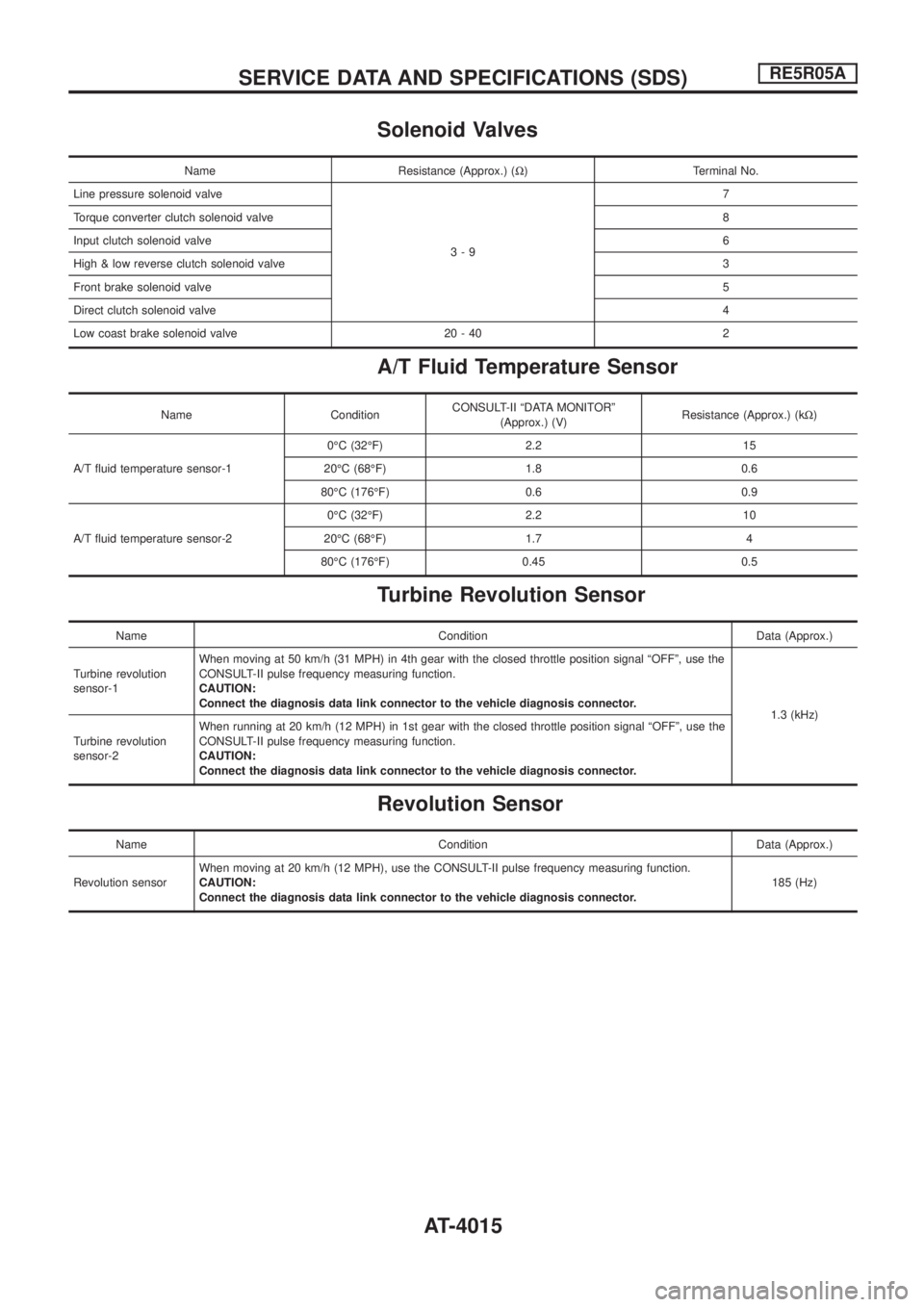
Solenoid Valves
Name Resistance (Approx.) (W) Terminal No.
Line pressure solenoid valve
3-97
Torque converter clutch solenoid valve8
Input clutch solenoid valve6
High & low reverse clutch solenoid valve3
Front brake solenoid valve5
Direct clutch solenoid valve4
Low coast brake solenoid valve 20 - 40 2
A/T Fluid Temperature Sensor
Name ConditionCONSULT-II ªDATA MONITORº
(Approx.) (V)Resistance (Approx.) (kW)
A/T ¯uid temperature sensor-10ÉC (32ÉF) 2.2 15
20ÉC (68ÉF) 1.8 0.6
80ÉC (176ÉF) 0.6 0.9
A/T ¯uid temperature sensor-20ÉC (32ÉF) 2.2 10
20ÉC (68ÉF) 1.7 4
80ÉC (176ÉF) 0.45 0.5
Turbine Revolution Sensor
Name Condition Data (Approx.)
Turbine revolution
sensor-1When moving at 50 km/h (31 MPH) in 4th gear with the closed throttle position signal ªOFFº, use the
CONSULT-II pulse frequency measuring function.
CAUTION:
Connect the diagnosis data link connector to the vehicle diagnosis connector.
1.3 (kHz)
Turbine revolution
sensor-2When running at 20 km/h (12 MPH) in 1st gear with the closed throttle position signal ªOFFº, use the
CONSULT-II pulse frequency measuring function.
CAUTION:
Connect the diagnosis data link connector to the vehicle diagnosis connector.
Revolution Sensor
Name Condition Data (Approx.)
Revolution sensorWhen moving at 20 km/h (12 MPH), use the CONSULT-II pulse frequency measuring function.
CAUTION:
Connect the diagnosis data link connector to the vehicle diagnosis connector.185 (Hz)
SERVICE DATA AND SPECIFICATIONS (SDS)RE5R05A
AT-4015
Page 34 of 579
Removal and Installation
Carefully observe the following steps during clutch tube removal
and installation.
+Do not spill clutch ¯uid onto painted surfaces. If it spills, wipe
up immediately and wash the affected area with water.
+When ®xing clutch hose to bracket, align clutch hose metal ®t-
tings with bracket positioning emboss and lock plate to secure.
At this time, prevent twisting or damage of clutch hose. In
addition, be careful not to damage clutch hose.
+Tighten clutch tube ¯are nut to the speci®ed torque.
CAUTION:
Be careful not to damage ¯are nut and clutch tube.
+Tighten the union bolt to the speci®ed torque.
CAUTION:
Do not reuse the copper washer.
+After installation, bleed the clutch tube.
PCIB0685E
PCIB0681E
CLUTCH PIPING
CL-4002
Page 442 of 579

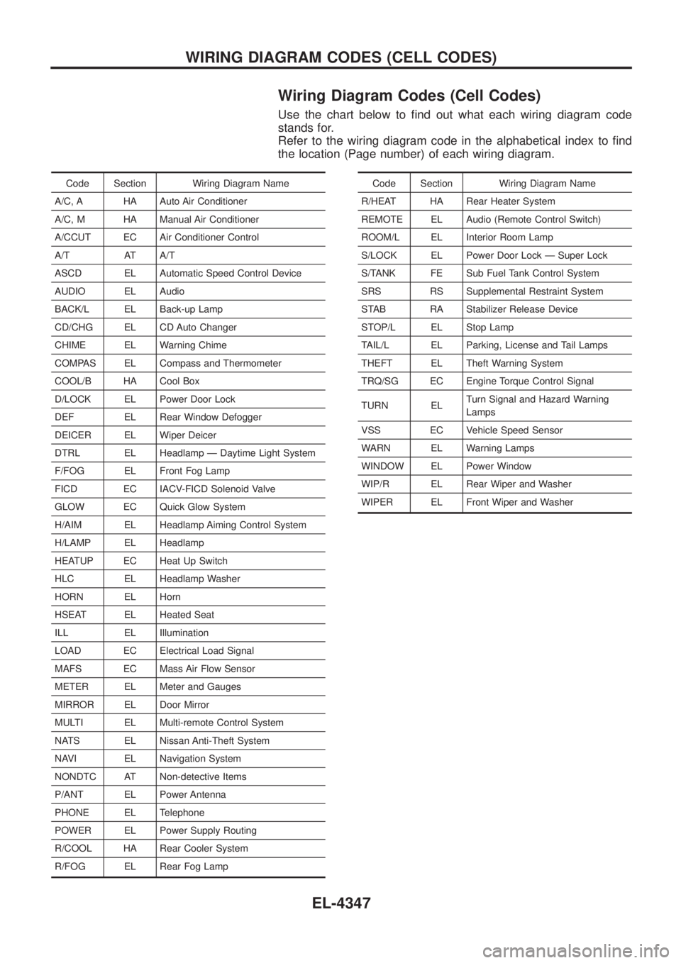
Wiring Diagram Codes (Cell Codes)
Use the chart below to ®nd out what each wiring diagram code
stands for.
Refer to the wiring diagram code in the alphabetical index to ®nd
the location (Page number) of each wiring diagram.
Code Section Wiring Diagram Name
A/C, A HA Auto Air Conditioner
A/C, M HA Manual Air Conditioner
A/CCUT EC Air Conditioner Control
A/T AT A/T
ASCD EL Automatic Speed Control Device
AUDIO EL Audio
BACK/L EL Back-up Lamp
CD/CHG EL CD Auto Changer
CHIME EL Warning Chime
COMPAS EL Compass and Thermometer
COOL/B HA Cool Box
D/LOCK EL Power Door Lock
DEF EL Rear Window Defogger
DEICER EL Wiper Deicer
DTRL EL Headlamp Ð Daytime Light System
F/FOG EL Front Fog Lamp
FICD EC IACV-FICD Solenoid Valve
GLOW EC Quick Glow System
H/AIM EL Headlamp Aiming Control System
H/LAMP EL Headlamp
HEATUP EC Heat Up Switch
HLC EL Headlamp Washer
HORN EL Horn
HSEAT EL Heated Seat
ILL EL Illumination
LOAD EC Electrical Load Signal
MAFS EC Mass Air Flow Sensor
METER EL Meter and Gauges
MIRROR EL Door Mirror
MULTI EL Multi-remote Control System
NATS EL Nissan Anti-Theft System
NAVI EL Navigation System
NONDTC AT Non-detective Items
P/ANT EL Power Antenna
PHONE EL Telephone
POWER EL Power Supply Routing
R/COOL HA Rear Cooler System
R/FOG EL Rear Fog LampCode Section Wiring Diagram Name
R/HEAT HA Rear Heater System
REMOTE EL Audio (Remote Control Switch)
ROOM/L EL Interior Room Lamp
S/LOCK EL Power Door Lock Ð Super Lock
S/TANK FE Sub Fuel Tank Control System
SRS RS Supplemental Restraint System
STAB RA Stabilizer Release Device
STOP/L EL Stop Lamp
TAIL/L EL Parking, License and Tail Lamps
THEFT EL Theft Warning System
TRQ/SG EC Engine Torque Control Signal
TURN EL Turn Signal and Hazard Warning
Lamps
VSS EC Vehicle Speed Sensor
WARN EL Warning Lamps
WINDOW EL Power Window
WIP/R EL Rear Wiper and Washer
WIPER EL Front Wiper and Washer
WIRING DIAGRAM CODES (CELL CODES)
EL-4347
Page 468 of 579
LHD MODELS
Installation
To install SMJ, tighten bolts until orange ªfulltightº mark appears
and then retighten to speci®ed torque as required.
: 3-5Nzm
(0.3 - 0.5 kg-m, 26 - 43 in-lb)
CAUTION:
Do not overtighten bolts, otherwise, they may be damaged.
RHD MODELS
Installation
To install SMJ, tighten bolts until orange ªfulltightº mark appears
and then retighten to speci®ed torque as required.
: 3-5N zm
(0.3 - 0.5 kg-m, 26 - 43 in-lb)
CAUTION:
Do not overtighten bolts, otherwise, they may be damaged.
CEL773
CEL789
CEL842
CEL841
SUPER MULTIPLE JUNCTION (SMJ)
EL-4348