2004 NISSAN PATROL ecm relay
[x] Cancel search: ecm relayPage 46 of 579
jB
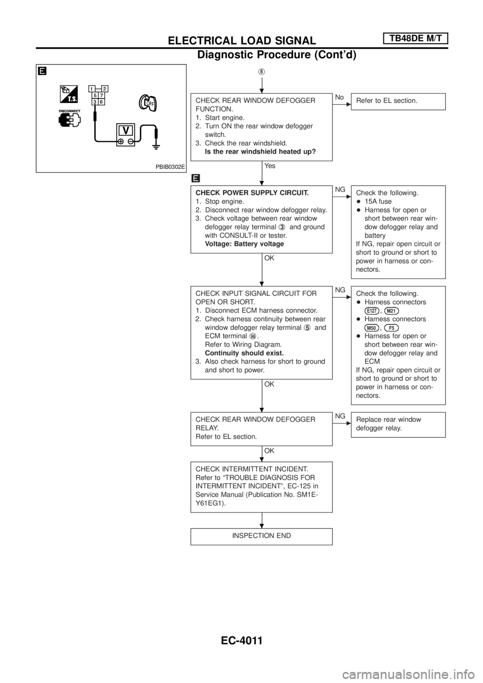
CHECK REAR WINDOW DEFOGGER
FUNCTION.
1. Start engine.
2. Turn ON the rear window defogger
switch.
3. Check the rear windshield.
Is the rear windshield heated up?
Ye s
cNo
Refer to EL section.
CHECK POWER SUPPLY CIRCUIT.
1. Stop engine.
2. Disconnect rear window defogger relay.
3. Check voltage between rear window
defogger relay terminalj
3and ground
with CONSULT-II or tester.
Voltage: Battery voltage
OK
cNG
Check the following.
+15A fuse
+Harness for open or
short between rear win-
dow defogger relay and
battery
If NG, repair open circuit or
short to ground or short to
power in harness or con-
nectors.
CHECK INPUT SIGNAL CIRCUIT FOR
OPEN OR SHORT.
1. Disconnect ECM harness connector.
2. Check harness continuity between rear
window defogger relay terminalj
5and
ECM terminalj
96.
Refer to Wiring Diagram.
Continuity should exist.
3. Also check harness for short to ground
and short to power.
OK
cNG
Check the following.
+Harness connectors
E127,M21
+Harness connectors
M50,F5
+Harness for open or
short between rear win-
dow defogger relay and
ECM
If NG, repair open circuit or
short to ground or short to
power in harness or con-
nectors.
CHECK REAR WINDOW DEFOGGER
RELAY.
Refer to EL section.
OK
cNG
Replace rear window
defogger relay.
CHECK INTERMITTENT INCIDENT.
Refer to ªTROUBLE DIAGNOSIS FOR
INTERMITTENT INCIDENTº, EC-125 in
Service Manual (Publication No. SM1E-
Y61EG1).
INSPECTION END
PBIB0302E
.
.
.
.
.
.
ELECTRICAL LOAD SIGNALTB48DE M/T
Diagnostic Procedure (Cont'd)
EC-4011
Page 75 of 579
ECM Terminals and Reference Value
ECM INSPECTION TABLE
Remarks: Speci®cation data are reference values and are measured between each terminal and ground.
CAUTION:
Do not use ECM ground terminals when measuring input/output voltage. Doing so may damage the
ECM's transistor. Use a ground other than ECM terminals, such as the ground.
TER-
MINAL
NO.WIRE
COLORITEM CONDITIONDATA (DC Voltage and Pulse
Signal)
2 R/WIntake air control valve
control solenoid valveEngine is running.
BATTERY VOLTAGE
(11 - 14V)
Ignition switch ªOFFº
For a few seconds after turning ignition
switch ªOFFºApproximately 0.1V
4 B/Y ECM relay (Self-shutoff)Ignition switch ªONº
Ignition switch ªOFFº
For a few seconds after turning ignition
switch ªOFFºApproximately 0.25V
Ignition switch ªOFFº
A few seconds passed after turning ignition
switch ªOFFºBATTERY VOLTAGE
(11 - 14V)
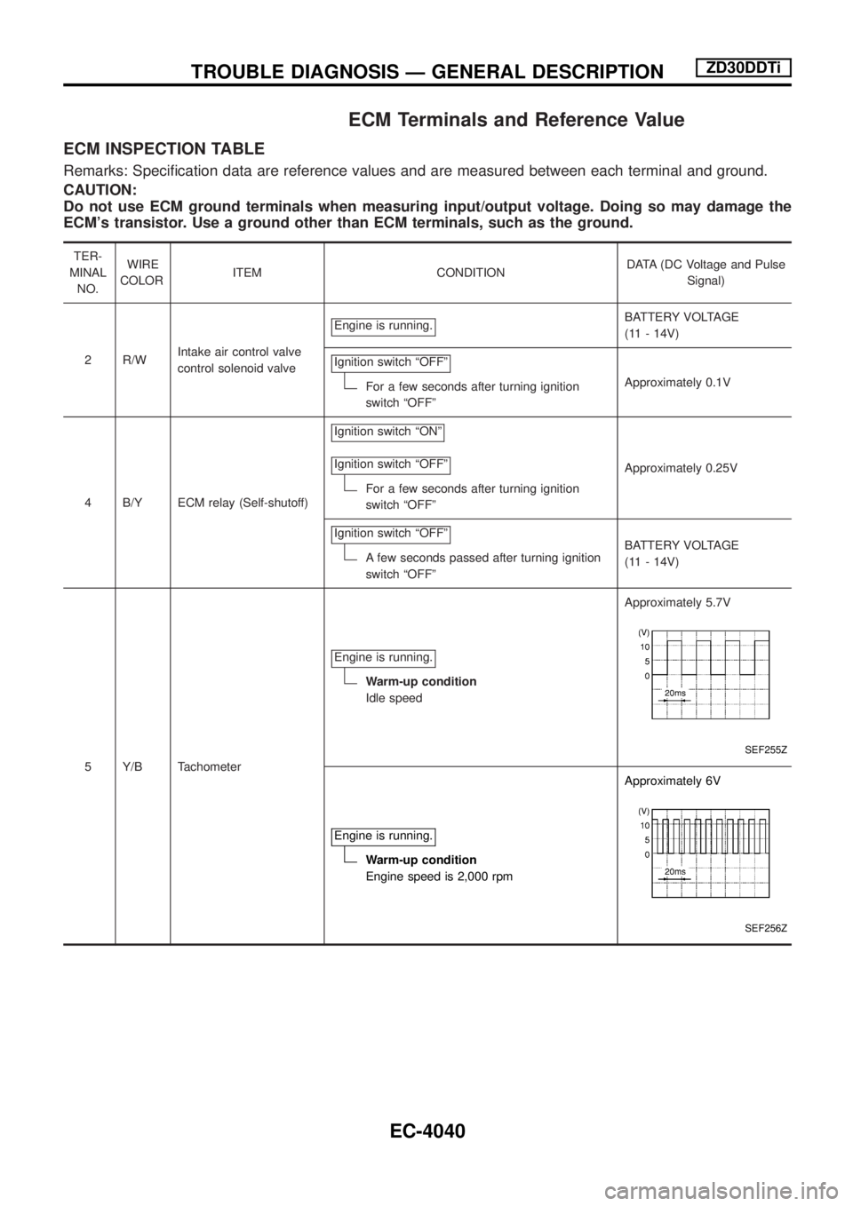
5 Y/B TachometerEngine is running.
Warm-up condition
Idle speedApproximately 5.7V
SEF255Z
Engine is running.
Warm-up condition
Engine speed is 2,000 rpmApproximately 6V
SEF256Z
TROUBLE DIAGNOSIS Ð GENERAL DESCRIPTIONZD30DDTi
EC-4040
Page 76 of 579
TER-
MINAL
NO.WIRE
COLORITEM CONDITIONDATA (DC Voltage and Pulse
Signal)
11 BR/YExhaust gas control
valve control solenoid
valveEngine is running.
Engine speed is below 1,200 rpm
Engine coolant temperature is below 87ÉC
(189ÉF)
Stop the vehicle
Heat up switch is ªONºApproximately 0.1V
Engine is running.
Except the above conditionBATTERY VOLTAGE
(11 - 14V)
14 L Cooling fan relayEngine is running.
Cooling fan is not operatingBATTERY VOLTAGE
(11 - 14V)
Engine is running.
Cooling fan is operatingApproximately 0.1V
15 Y/L Air conditioner relayEngine is running.
Air conditioner switch is ªOFFºBATTERY VOLTAGE
(11 - 14V)
Engine is running.
Both air conditioner switch and blower fan
switch are ªONº
(Compressor is operating)Approximately 0.1V
16 L/W Glow lampIgnition switch ªONº
Glow lamp is ªONºApproximately 1V
Ignition switch ªONº
Glow lamp is ªOFFºBATTERY VOLTAGE
(11 - 14V)
17 G/Y Stop lamp switchIgnition switch ªONº
Brake pedal fully releasedApproximately 0V
Ignition switch ªONº
Brake pedal depressedBATTERY VOLTAGE
(11 - 14V)
18 GMalfunction indicator
lampIgnition switch ªONº
Approximately 1V
Engine is running.
Idle speedBATTERY VOLTAGE
(11 - 14V)
19 LG/REngine coolant tempera-
ture sensorEngine is running.
Approximately 0 - 4.8V
Output voltage varies with
engine coolant temperature
20 R/W Start signalIgnition switch ªONº
Approximately 0V
Ignition switch ªSTARTº
BATTERY VOLTAGE
(11 - 14V)
TROUBLE DIAGNOSIS Ð GENERAL DESCRIPTIONZD30DDTi
ECM Terminals and Reference Value (Cont'd)
EC-4041
Page 81 of 579
TER-
MINAL
NO.WIRE
COLORITEM CONDITIONDATA (DC Voltage and Pulse
Signal)
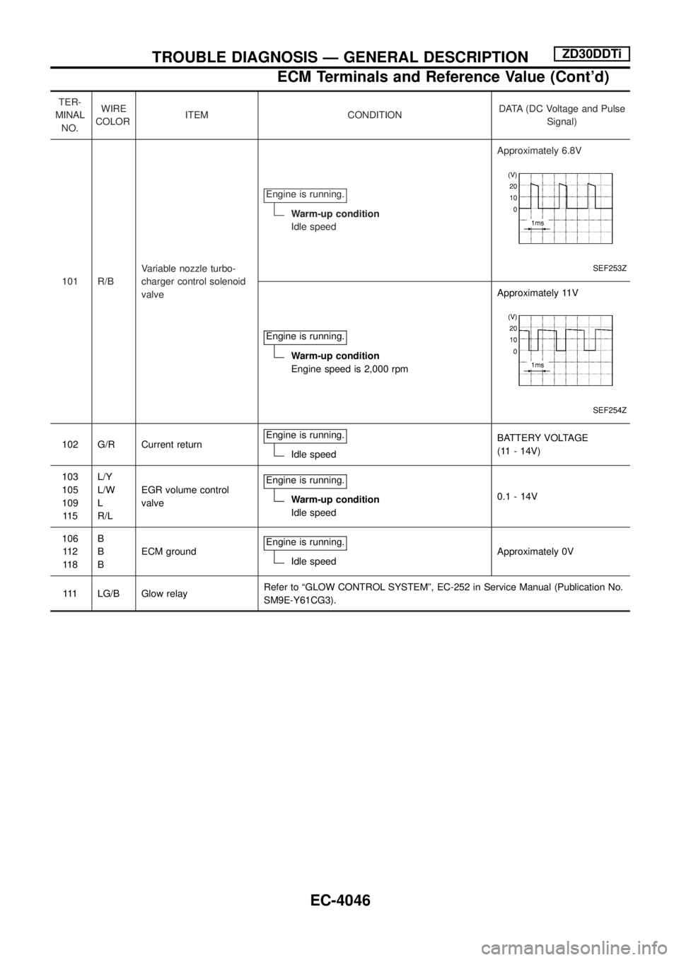
101 R/BVariable nozzle turbo-
charger control solenoid
valveEngine is running.
Warm-up condition
Idle speedApproximately 6.8V
SEF253Z
Engine is running.
Warm-up condition
Engine speed is 2,000 rpmApproximately 11V
SEF254Z
102 G/R Current returnEngine is running.Idle speedBATTERY VOLTAGE
(11 - 14V)
103
105
109
11 5L/Y
L/W
L
R/LEGR volume control
valveEngine is running.
Warm-up condition
Idle speed0.1 - 14V
106
11 2
11 8B
B
BECM groundEngine is running.
Idle speedApproximately 0V
111 LG/B Glow relayRefer to ªGLOW CONTROL SYSTEMº, EC-252 in Service Manual (Publication No.
SM9E-Y61CG3).
TROUBLE DIAGNOSIS Ð GENERAL DESCRIPTIONZD30DDTi
ECM Terminals and Reference Value (Cont'd)
EC-4046
Page 85 of 579
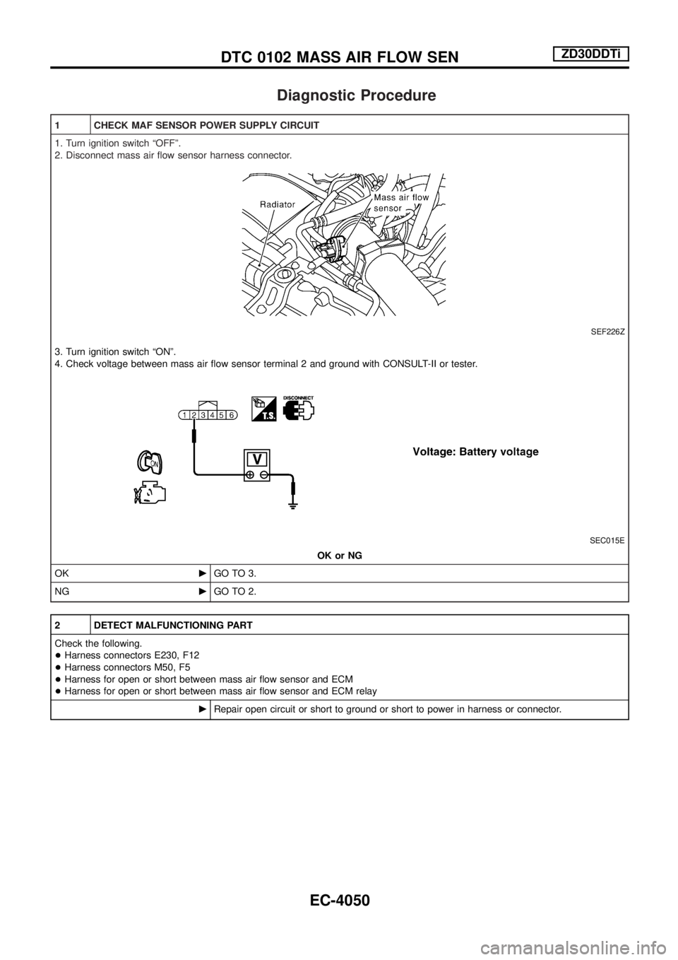
Diagnostic Procedure
1 CHECK MAF SENSOR POWER SUPPLY CIRCUIT
1. Turn ignition switch ªOFFº.
2. Disconnect mass air ¯ow sensor harness connector.
SEF226Z
3. Turn ignition switch ªONº.
4. Check voltage between mass air ¯ow sensor terminal 2 and ground with CONSULT-II or tester.
SEC015E
OK or NG
OKcGO TO 3.
NGcGO TO 2.
2 DETECT MALFUNCTIONING PART
Check the following.
+Harness connectors E230, F12
+Harness connectors M50, F5
+Harness for open or short between mass air ¯ow sensor and ECM
+Harness for open or short between mass air ¯ow sensor and ECM relay
cRepair open circuit or short to ground or short to power in harness or connector.
DTC 0102 MASS AIR FLOW SENZD30DDTi
EC-4050
Page 520 of 579
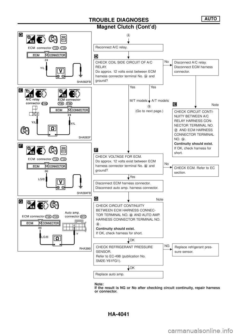
jA
Reconnect A/C relay.
CHECK COIL SIDE CIRCUIT OF A/C
RELAY.
Do approx. 12 volts exist between ECM
harness connector terminal No.j
24and
ground?
Ye s
Ye s
cNo
Disconnect A/C relay.
Disconnect ECM harness
connector.
jB
(Go to next page.)
Note
CHECK CIRCUIT CONTI-
NUITY BETWEEN A/C
RELAY HARNESS CON-
NECTOR TERMINAL NO.
j
2AND ECM HARNESS
CONNECTOR TERMINAL
NO.j
24.
Continuity should exist.
If OK, check harness for
short.
M/T models A/T models
CHECK VOLTAGE FOR ECM.
Do approx. 12 volts exist between ECM
harness connector terminal No.j
86and
ground?
Ye s
cNo
CHECK ECM. Refer to EC
section.
Disconnect ECM harness connector.
Disconnect auto amp. harness connector.
Note
CHECK CIRCUIT CONTINUITY
BETWEEN ECM HARNESS CONNEC-
TOR TERMINAL NO.j
86AND AUTO AMP.
HARNESS CONNECTOR TERMINAL NO.
j
4.
Continuity should exist.
If OK, check harness for short.
OK
CHECK REFRIGERANT PRESSURE
SENSOR.
Refer to EC-498 (publication No.
SM2E-Y61FG1).
OK
cNG
Replace refrigerant pres-
sure sensor.
Replace auto amp.
Note:
If the result is NG or No after checking circuit continuity, repair harness
or connector.
SHA582FB
SHA583F
SHA584FB
RHA386I
.
.
.
.
.
.
.
.
.
TROUBLE DIAGNOSESAUTO
Magnet Clutch (Cont'd)
HA-4041
Page 523 of 579
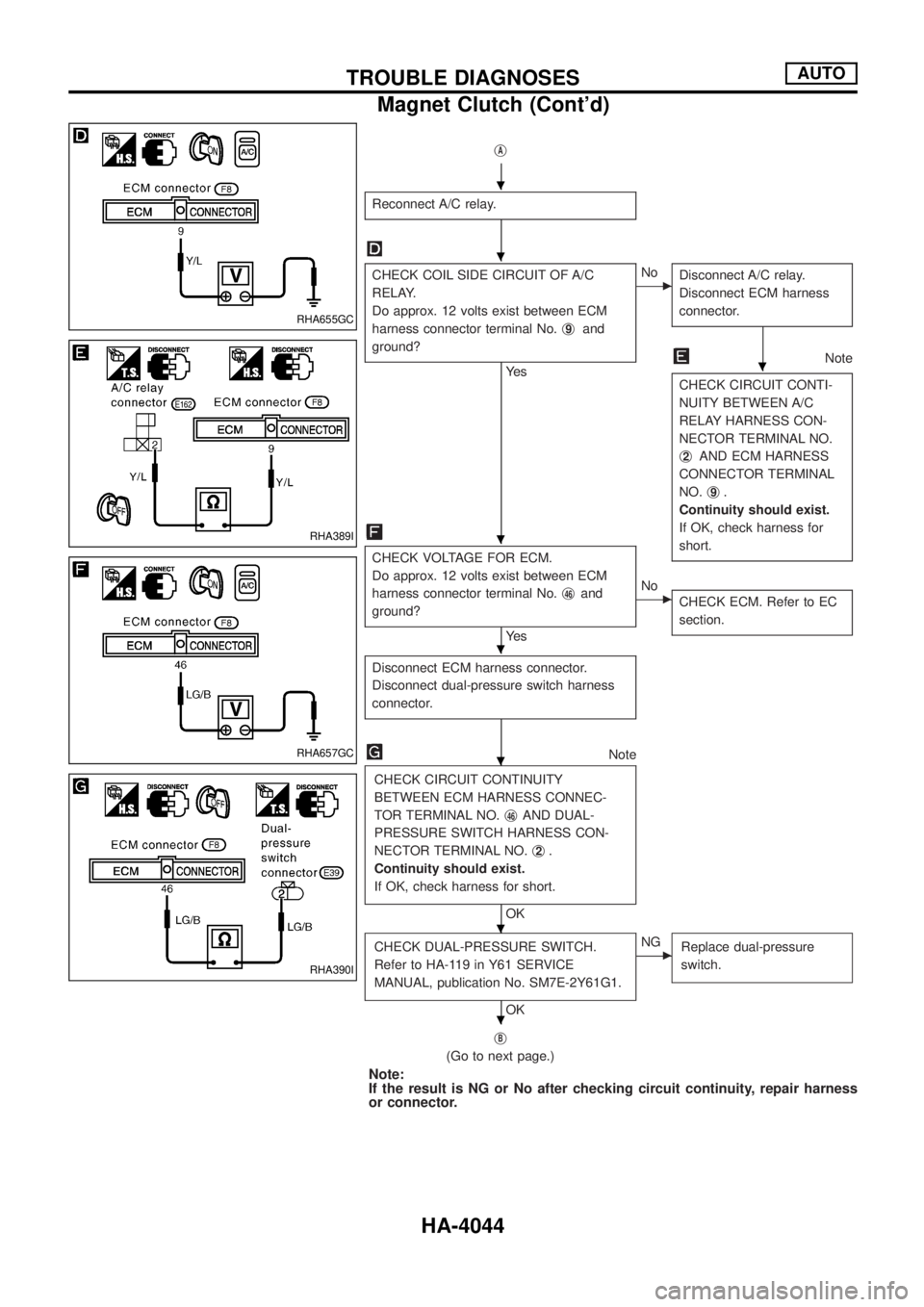
jA
Reconnect A/C relay.
CHECK COIL SIDE CIRCUIT OF A/C
RELAY.
Do approx. 12 volts exist between ECM
harness connector terminal No.j
9and
ground?
Ye s
cNo
Disconnect A/C relay.
Disconnect ECM harness
connector.
Note
CHECK CIRCUIT CONTI-
NUITY BETWEEN A/C
RELAY HARNESS CON-
NECTOR TERMINAL NO.
j
2AND ECM HARNESS
CONNECTOR TERMINAL
NO.j
9.
Continuity should exist.
If OK, check harness for
short.
CHECK VOLTAGE FOR ECM.
Do approx. 12 volts exist between ECM
harness connector terminal No.j
46and
ground?
Ye s
cNo
CHECK ECM. Refer to EC
section.
Disconnect ECM harness connector.
Disconnect dual-pressure switch harness
connector.
Note
CHECK CIRCUIT CONTINUITY
BETWEEN ECM HARNESS CONNEC-
TOR TERMINAL NO.j
46AND DUAL-
PRESSURE SWITCH HARNESS CON-
NECTOR TERMINAL NO.j
2.
Continuity should exist.
If OK, check harness for short.
OK
CHECK DUAL-PRESSURE SWITCH.
Refer to HA-119 in Y61 SERVICE
MANUAL, publication No. SM7E-2Y61G1.
OK
cNG
Replace dual-pressure
switch.
jB
(Go to next page.)
Note:
If the result is NG or No after checking circuit continuity, repair harness
or connector.
RHA655GC
RHA389I
RHA657GC
RHA390I
.
.
.
.
.
.
.
.
TROUBLE DIAGNOSESAUTO
Magnet Clutch (Cont'd)
HA-4044
Page 529 of 579
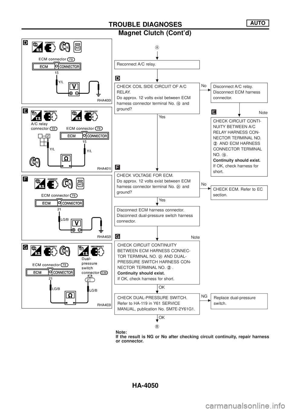
jA
Reconnect A/C relay.
CHECK COIL SIDE CIRCUIT OF A/C
RELAY.
Do approx. 12 volts exist between ECM
harness connector terminal No.j
15and
ground?
Ye s
cNo
Disconnect A/C relay.
Disconnect ECM harness
connector.
Note
CHECK CIRCUIT CONTI-
NUITY BETWEEN A/C
RELAY HARNESS CON-
NECTOR TERMINAL NO.
j
2AND ECM HARNESS
CONNECTOR TERMINAL
NO.j
15.
Continuity should exist.
If OK, check harness for
short.
CHECK VOLTAGE FOR ECM.
Do approx. 12 volts exist between ECM
harness connector terminal No.j
21and
ground?
Ye s
cNo
CHECK ECM. Refer to EC
section.
Disconnect ECM harness connector.
Disconnect dual-pressure switch harness
connector.
Note
CHECK CIRCUIT CONTINUITY
BETWEEN ECM HARNESS CONNEC-
TOR TERMINAL NO.j
21AND DUAL-
PRESSURE SWITCH HARNESS CON-
NECTOR TERMINAL NO.j
2.
Continuity should exist.
If OK, check harness for short.
OK
CHECK DUAL-PRESSURE SWITCH.
Refer to HA-119 in Y61 SERVICE
MANUAL, publication No. SM7E-2Y61G1.
OK
cNG
Replace dual-pressure
switch.
jB
Note:
If the result is NG or No after checking circuit continuity, repair harness
or connector.
RHA400I
RHA401I
RHA402I
RHA403I
.
.
.
.
.
.
.
.
TROUBLE DIAGNOSESAUTO
Magnet Clutch (Cont'd)
HA-4050