Page 76 of 579
TER-
MINAL
NO.WIRE
COLORITEM CONDITIONDATA (DC Voltage and Pulse
Signal)
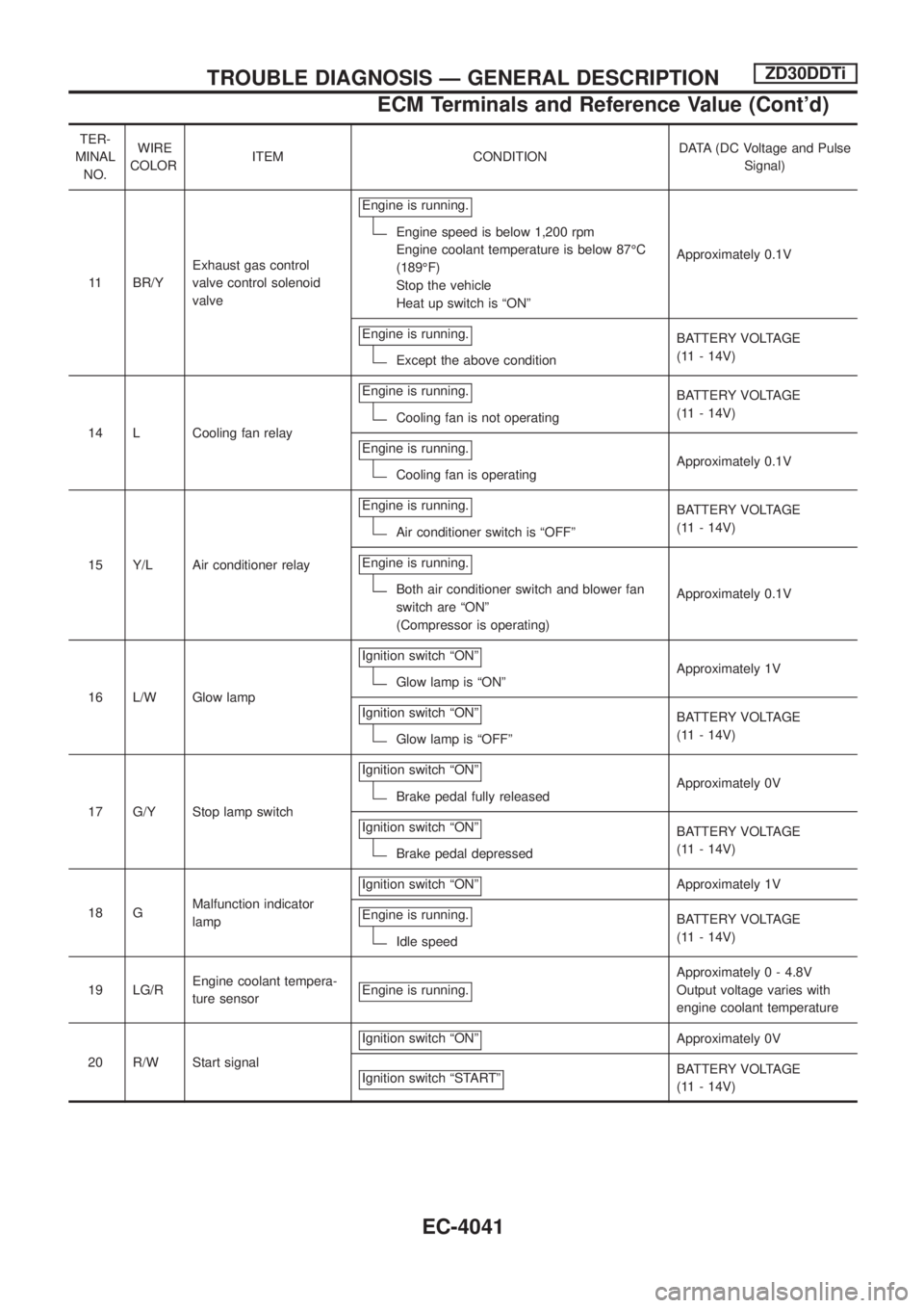
11 BR/YExhaust gas control
valve control solenoid
valveEngine is running.
Engine speed is below 1,200 rpm
Engine coolant temperature is below 87ÉC
(189ÉF)
Stop the vehicle
Heat up switch is ªONºApproximately 0.1V
Engine is running.
Except the above conditionBATTERY VOLTAGE
(11 - 14V)
14 L Cooling fan relayEngine is running.
Cooling fan is not operatingBATTERY VOLTAGE
(11 - 14V)
Engine is running.
Cooling fan is operatingApproximately 0.1V
15 Y/L Air conditioner relayEngine is running.
Air conditioner switch is ªOFFºBATTERY VOLTAGE
(11 - 14V)
Engine is running.
Both air conditioner switch and blower fan
switch are ªONº
(Compressor is operating)Approximately 0.1V
16 L/W Glow lampIgnition switch ªONº
Glow lamp is ªONºApproximately 1V
Ignition switch ªONº
Glow lamp is ªOFFºBATTERY VOLTAGE
(11 - 14V)
17 G/Y Stop lamp switchIgnition switch ªONº
Brake pedal fully releasedApproximately 0V
Ignition switch ªONº
Brake pedal depressedBATTERY VOLTAGE
(11 - 14V)
18 GMalfunction indicator
lampIgnition switch ªONº
Approximately 1V
Engine is running.
Idle speedBATTERY VOLTAGE
(11 - 14V)
19 LG/REngine coolant tempera-
ture sensorEngine is running.
Approximately 0 - 4.8V
Output voltage varies with
engine coolant temperature
20 R/W Start signalIgnition switch ªONº
Approximately 0V
Ignition switch ªSTARTº
BATTERY VOLTAGE
(11 - 14V)
TROUBLE DIAGNOSIS Ð GENERAL DESCRIPTIONZD30DDTi
ECM Terminals and Reference Value (Cont'd)
EC-4041
Page 83 of 579
DTC Con®rmation Procedure
WITH CONSULT-II
1) Turn ignition switch ªONº, and wait at least 6 seconds.
2) Select ªDATA MONITORº mode with CONSULT-II.
3) Start engine and wait at least 3 seconds.
4) If DTC is detected, go to ªDiagnostic Procedureº, EC-4050.
WITHOUT CONSULT-II
1) Turn ignition switch ªONº, and wait at least 6 seconds.
2) Start engine and wait at least 3 seconds.
3) Turn ignition switch ªOFFº, wait at least 5 seconds and then turn
ªONº.
4) Perform ªDiagnostic Test Mode II (Self-diagnostic results)º with
ECM.
5) If DTC is detected, go to ªDiagnostic Procedureº, EC-4050.
SEF817Y
DTC 0102 MASS AIR FLOW SENZD30DDTi
EC-4048
Page 87 of 579
7 CHECK SHIELD CIRCUIT
1. Disconnect harness connectors E230, F12.
2. Check harness continuity between harness connector F12 terminal 5 and ground.
Refer to Wiring Diagram.
Continuity should exist.
3. Also check harness for short to power.
OK or NG
OKcGO TO 9.
NGcGO TO 8.
8 DETECT MALFUNCTIONING PART
Check the following.
+Joint connector-4
+Harness for open or short between harness connector F12 and ground
cRepair open circuit or short to power in harness or connectors.
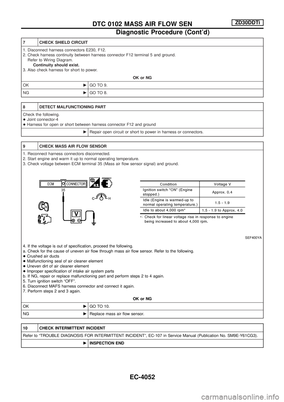
9 CHECK MASS AIR FLOW SENSOR
1. Reconnect harness connectors disconnected.
2. Start engine and warm it up to normal operating temperature.
3. Check voltage between ECM terminal 35 (Mass air ¯ow sensor signal) and ground.
SEF400YA
4. If the voltage is out of speci®cation, proceed the following.
a. Check for the cause of uneven air ¯ow through mass air ¯ow sensor. Refer to the following.
+Crushed air ducts
+Malfunctioning seal of air cleaner element
+Uneven dirt of air cleaner element
+Improper speci®cation of intake air system parts
b. If NG, repair or replace malfunctioning part and perform steps 2 to 4 again.
5. Turn ignition switch ªOFFº.
6. Disconnect MAFS harness connector and connect it again.
7. Perform steps 2 and 3 again.
OK or NG
OKcGO TO 10.
NGcReplace mass air ¯ow sensor.
10 CHECK INTERMITTENT INCIDENT
Refer to ªTROUBLE DIAGNOSIS FOR INTERMITTENT INCIDENTº, EC-107 in Service Manual (Publication No. SM9E-Y61CG3).
cINSPECTION END
DTC 0102 MASS AIR FLOW SENZD30DDTi
Diagnostic Procedure (Cont'd)
EC-4052
Page 90 of 579
Diagnostic Procedure
1 INSPECTION START
Do you have CONSULT-II?
YesorNo
Ye scGO TO 2.
NocGO TO 3.
2 CHECK OVERALL FUNCTION
With CONSULT-II
1. Turn ignition switch ªONº.
2. Check ªWARM UP SWº in ªDATA MONITORº mode with CONSULT-II under the following conditions.
SEF302Z
OK or NG
OKcINSPECTION END
NGcGO TO 4.
3 CHECK OVERALL FUNCTION
Without CONSULT-II
1. Turn ignition switch ªONº.
2. Check voltage between ECM terminal 59 and ground under the following conditions.
SEF303Z
OK or NG
OKcINSPECTION END
NGcGO TO 4.
HEAT UP SWITCHZD30DDTi
EC-4055
Page 107 of 579
IGNITION POWER SUPPLY Ð IGNITION SW. IN ªONº AND/OR ªSTARTº
TEL968M
POWER SUPPLY ROUTING/WAGON AND HARDTOP MODELS
Wiring Diagram Ð POWER Ð (Cont'd)EL-4012
Page 262 of 579
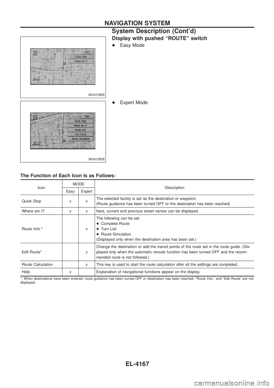
Display with pushed ªROUTEº switch
+Easy Mode
+ Expert Mode
The Function of Each Icon Is as Follows:
Icon MODE
Description
Easy Expert
Quick Stop x x The selected facility is set as the destination or waypoint.
(Route guidance has been turned OFF or the destination has been reached)
Where am I? x x Next, current and previous street names can be displayed.
Route Info.* x The following can be set.
+
Complete Route
+ Turn List
+ Route Simulation
(Displayed only when the destination area has been set.)
Edit Route* x Change the destination or add the transit points of the route set in the route guide. (Dis-
played only when the automatic reroute function has been turned OFF and the recom-
mended route is not followed.)
Route Calculation x This key is used to start the route calculation after all the settings are completed.
Help x Explanation of navigational functions appear on the display.
*: When destinations have been entered, route guidance has been turned OFF or destination has been reached, ªRoute Info.º and ªEdit Routeº are not
displayed.
SKIA1382E
SKIA1383E
NAVIGATION SYSTEM
System Description (Cont'd)
EL-4167
Page 264 of 579
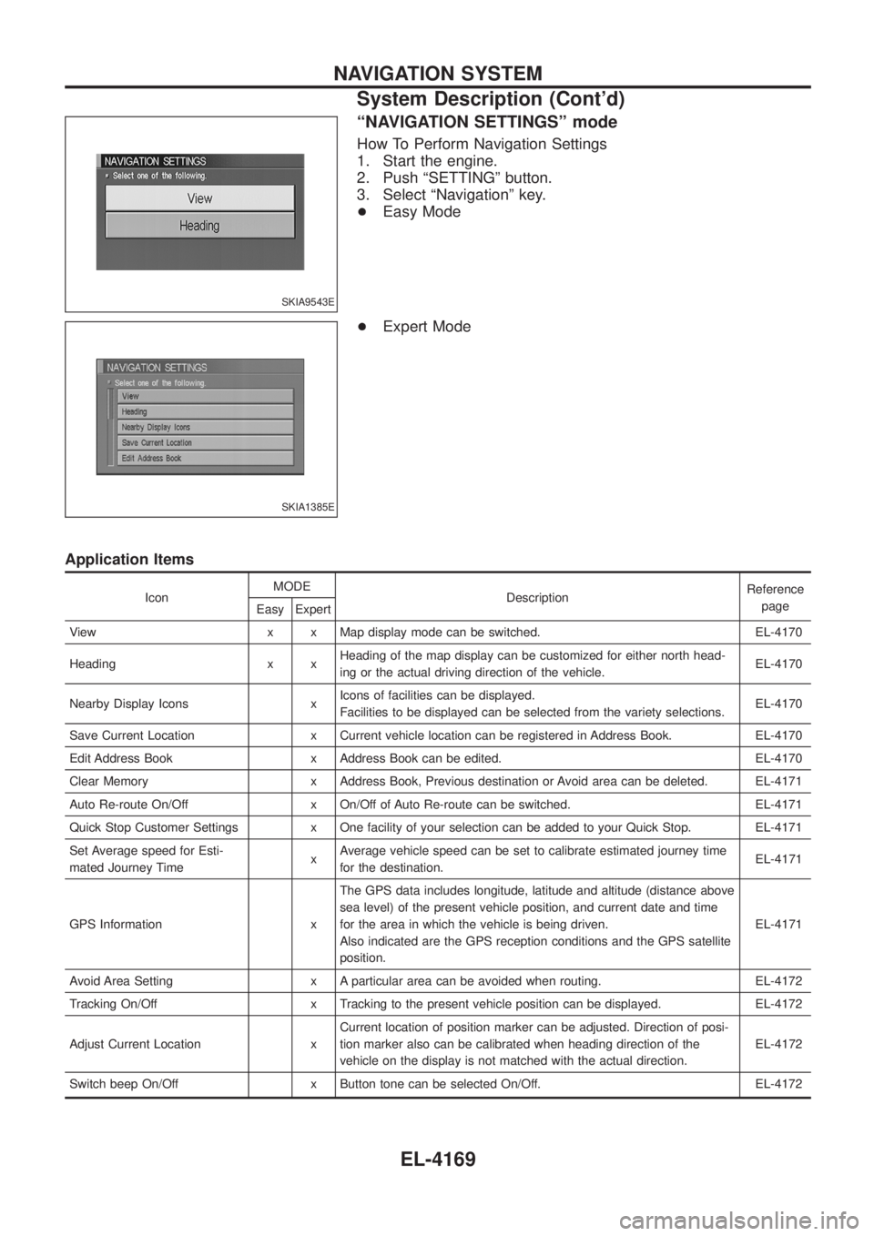
ªNAVIGATION SETTINGSº mode
How To Perform Navigation Settings
1. Start the engine.
2. Push ªSETTINGº button.
3. Select ªNavigationº key.
+Easy Mode
+ Expert Mode
Application Items
Icon MODE
Description Reference
page
Easy Expert
View x x Map display mode can be switched. EL-4170
Heading x x Heading of the map display can be customized for either north head-
ing or the actual driving direction of the vehicle. EL-4170
Nearby Display Icons x Icons of facilities can be displayed.
Facilities to be displayed can be selected from the variety selections. EL-4170
Save Current Location x Current vehicle location can be registered in Address Book. EL-4170
Edit Address Book x Address Book can be edited. EL-4170
Clear Memory x Address Book, Previous destination or Avoid area can be deleted. EL-4171
Auto Re-route On/Off x On/Off of Auto Re-route can be switched. EL-4171
Quick Stop Customer Settings x One facility of your selection can be added to your Quick Stop. EL-4171
Set Average speed for Esti-
mated Journey Time xAverage vehicle speed can be set to calibrate estimated journey time
for the destination. EL-4171
GPS Information x The GPS data includes longitude, latitude and altitude (distance above
sea level) of the present vehicle position, and current date and time
for the area in which the vehicle is being driven.
Also indicated are the GPS reception conditions and the GPS satellite
position. EL-4171
Avoid Area Setting x A particular area can be avoided when routing. EL-4172
Tracking On/Off x Tracking to the present vehicle position can be displayed. EL-4172
Adjust Current Location x Current location of position marker can be adjusted. Direction of posi-
tion marker also can be calibrated when heading direction of the
vehicle on the display is not matched with the actual direction. EL-4172
Switch beep On/Off x Button tone can be selected On/Off. EL-4172
SKIA9543E
SKIA1385E
NAVIGATION SYSTEM
System Description (Cont'd)
EL-4169
Page 284 of 579
Self-Diagnosis Function
DESCRIPTION
+Diagnosis function consists of the self-diagnosis mode performed automatically and the CONFIRMATION/
ADJUSTMENT mode operated manually.
+ Self-diagnosis mode checks for connections between the units constituting this system, analyzes each
individual unit at the same time, and displays the results on the LCD screen.
+ CONFIRMATION/ADJUSTMENT mode is used to perform trouble diagnosis that require operation and
judgment by an operator (malfunction that cannot be automatically judged by the system), to check/change
the set value, and to display the History of Errors of the navigation system.
DIAGNOSIS ITEM
Mode Description
Self-diagnosis +
NAVI Control unit diagnosis (DVD-ROM drive will not be diagnosed when no
map DVD-ROM is in it.).
+ Performs diagnosis of each unit and connections between control unit and
GPS antenna, as well as between control unit and each unit.
Con®rmation/
Adjustment Display
Color tone and shading of the screen can be checked by the display of a color
bar and a gray scale.
Vehicle signals Analyzes the following vehicle signals: Vehicle speed signal, light signal, ignition
switch signal, and reverse signal.
Navigation Display Longi-
tude & Lati-
tude
Display the map. Use the joystick to adjust position. Longitude and latitude will be
displayed.
Speed Calibra-
tion Under ordinary conditions, the navigation system distance measuring function will
automatically compensate for minute decreases in wheel and tire diameter
caused by tire wear or low-pressure. Speed calibration immediately restores sys-
tem accuracy in cases such as when distance calibration is needed because of
the use of tire chains in inclement weather.
Angle Adjust-
ment Corrects difference between actual turning angle of a vehicle and turning angle of
the car mark on the display.
Initialize Loca-
tion This mode is for initializing the current location. Use when the vehicle is trans-
ported a long distance on a trailer, etc.
History of Errors Diagnosis results previously stored in the memory (before turning ignition switch
ON) are displayed in this mode. Time and location when/where the errors
occurred are also displayed.
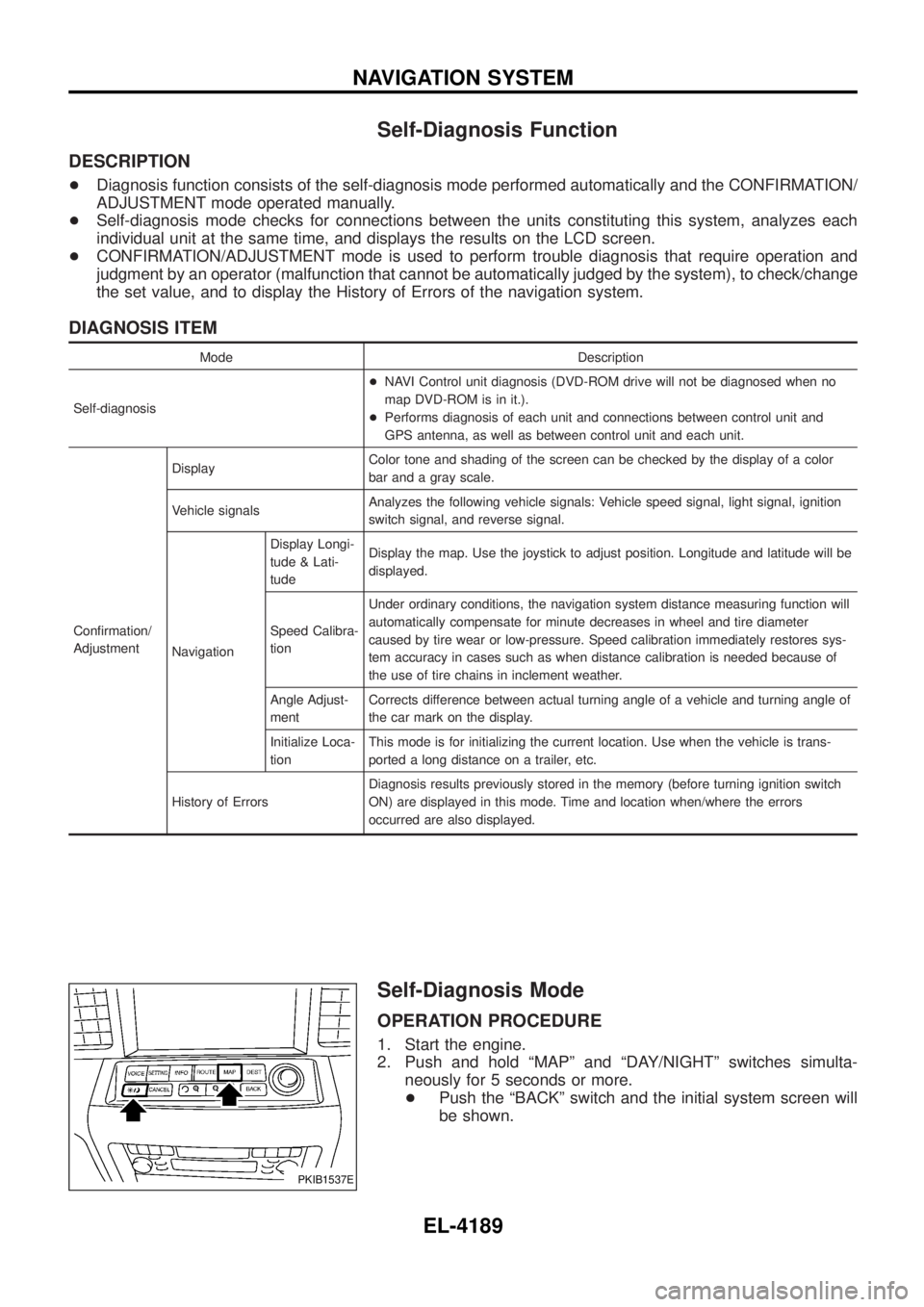
Self-Diagnosis Mode
OPERATION PROCEDURE
1. Start the engine.
2. Push and hold ªMAPº and ªDAY/NIGHTº switches simulta-
neously for 5 seconds or more.
+ Push the ªBACKº switch and the initial system screen will
be shown.
PKIB1537E
NAVIGATION SYSTEM
EL-4189