Page 1 of 579
Edition: July 2004
Release: July 2004 (01)
Publication No.: SM4E00-1Y61E0E
Reference No.: 7711347233GENERAL INFORMATIONGI
MAINTENANCEMA
ENGINE MECHANICALEM
ENGINE LUBRICATION &
COOLING SYSTEMSLC
ENGINE CONTROL SYSTEMEC
ACCELERATOR CONTROL,
FUEL & EXHAUST SYSTEMFE
CLUTCHCL
MANUAL TRANSMISSIONMT
AUTOMATIC TRANSMISSIONAT
TRANSFERTF
PROPELLER SHAFT &
DIFFERENTIAL CARRIERPD
FRONT AXLE & FRONT SUSPENSIONFA
REAR AXLE & REAR SUSPENSIONRA
BRAKE SYSTEMBR
STEERING SYSTEMST
RESTRAINT SYSTEMRS
BODY & TRIMBT
HEATER & AIR CONDITIONERHA
ELECTRICAL SYSTEMEL
ALPHABETICAL INDEXIDX
PATROL
MODEL Y61 SERIES
NISSAN EUROPE S.A.S.
2004 NISSAN EUROPE S.A.S.
Produced in The Netherlands
Not to be reproduced in whole or in part
without the prior written permission of
Nissan Europe S.A.S., Paris, France.
QUICK REFERENCE INDEX
Page 21 of 579
\
BODY&TRIM
SECTION
BT
MODIFICATION NOTICE:
Following parts have been changed:
+ Front bumper
+ Rear bumper
+ Instrument panel
+ Overfender
+ License lamp ®nisher
+ Rear seat
CONTENTS
BODY END ................................................................4002
Body Front End......................................................4002
Body Rear End and Opener ..................................4005
INSTRUMENT PANEL ...............................................4006 EXTERIOR
.................................................................4009
SEAT ........................................................................\
..4012
Rear Seat...............................................................4012
H For seat belt, refer to MA and RS section.
H For wiring diagrams of body electrical systems, refer to EL section.
BT-4001
Page 36 of 579

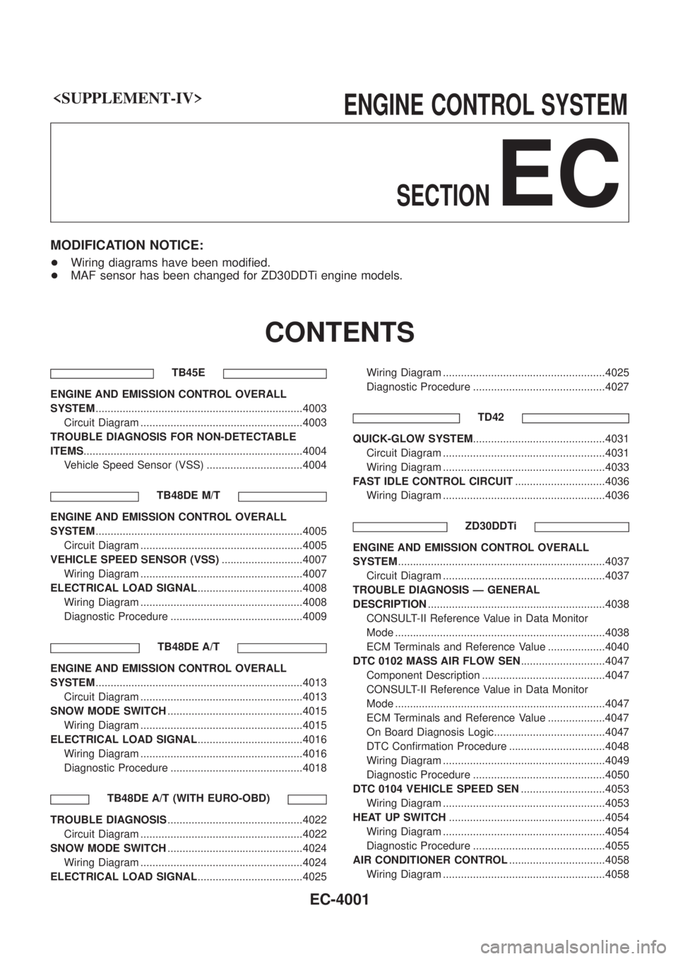
ENGINECONTROLSYSTEM
SECTION
EC
MODIFICATION NOTICE:
+Wiring diagrams have been modi®ed.
+ MAF sensor has been changed for ZD30DDTi engine models.
CONTENTS
TB45E
ENGINE AND EMISSION CONTROL OVERALL
SYSTEM .....................................................................4003
Circuit Diagram ......................................................4003
TROUBLE DIAGNOSIS FOR NON-DETECTABLE
ITEMS ........................................................................\
.4004
Vehicle Speed Sensor (VSS) ................................4004
TB48DE M/T
ENGINE AND EMISSION CONTROL OVERALL
SYSTEM.....................................................................4005
Circuit Diagram ......................................................4005
VEHICLE SPEED SENSOR (VSS) ...........................4007
Wiring Diagram ......................................................4007
ELECTRICAL LOAD SIGNAL ...................................4008
Wiring Diagram ......................................................4008
Diagnostic Procedure ............................................4009
TB48DE A/T
ENGINE AND EMISSION CONTROL OVERALL
SYSTEM.....................................................................4013
Circuit Diagram ......................................................4013
SNOW MODE SWITCH .............................................4015
Wiring Diagram ......................................................4015
ELECTRICAL LOAD SIGNAL ...................................4016
Wiring Diagram ......................................................4016
Diagnostic Procedure ............................................4018
TB48DE A/T (WITH EURO-OBD)
TROUBLE DIAGNOSIS .............................................4022
Circuit Diagram ......................................................4022
SNOW MODE SWITCH .............................................4024
Wiring Diagram ......................................................4024
ELECTRICAL LOAD SIGNAL ...................................4025 Wiring Diagram ......................................................4025
Diagnostic Procedure ............................................4027
TD42
QUICK-GLOW SYSTEM ............................................4031
Circuit Diagram ......................................................4031
Wiring Diagram ......................................................4033
FAST IDLE CONTROL CIRCUIT ..............................4036
Wiring Diagram ......................................................4036
ZD30DDTi
ENGINE AND EMISSION CONTROL OVERALL
SYSTEM.....................................................................4037
Circuit Diagram ......................................................4037
TROUBLE DIAGNOSIS Ð GENERAL
DESCRIPTION ...........................................................4038
CONSULT-II Reference Value in Data Monitor
Mode ......................................................................4038
ECM Terminals and Reference Value ...................4040
DTC 0102 MASS AIR FLOW SEN ............................4047
Component Description .........................................4047
CONSULT-II Reference Value in Data Monitor
Mode ......................................................................4047
ECM Terminals and Reference Value ...................4047
On Board Diagnosis Logic.....................................4047
DTC Con®rmation Procedure ................................4048
Wiring Diagram ......................................................4049
Diagnostic Procedure ............................................4050
DTC 0104 VEHICLE SPEED SEN ............................4053
Wiring Diagram ......................................................4053
HEAT UP SWITCH ....................................................4054
Wiring Diagram ......................................................4054
Diagnostic Procedure ............................................4055
AIR CONDITIONER CONTROL ................................4058
Wiring Diagram ......................................................4058
EC-4001
Page 37 of 579
TD42Ti
ENGINE AND EMISSION CONTROL OVERALL
SYSTEM.....................................................................4059
Circuit Diagram ......................................................4059TROUBLE DIAGNOSES FOR NON-DETECTABLE
ITEMS.........................................................................4060
Vehicle Speed Sensor (VSS) ................................4060
When you read wiring diagrams:
+Read GI section, ªHOW TO READ WIRING DIAGRAMSº.
+See EL section, ªPOWER SUPPLY ROUTINGº for power distribution circuit.
When you perform trouble diagnoses, read GI section, ªHOW TO FOLLOW FLOW CHART IN
TROUBLE DIAGNOSESº and ªHOW TO PERFORM EFFICIENT DIAGNOSIS FOR AN ELECTRICAL
INCIDENTº.
CONTENTS(Cont'd)
EC-4002
Page 43 of 579
Wiring Diagram
TEC517M
ELECTRICAL LOAD SIGNALTB48DE M/T
EC-4008
Page 44 of 579
Diagnostic Procedure
INSPECTION START
Do you have CONSULT-II?
Ye s
cNo
Go tojA. (Without CON-
SULT-II)
CHECK OVERALL FUNCTION-I.
With CONSULT-II
1. Turn ignition switch ON.
2. Check ªLOAD SIGNALº in ªDATA
MONITORº mode with CONSULT-II.
Rear window defogger ON
LOAD SIGNAL: ON
Rear window defogger OFF
LOAD SIGNAL: OFF
OK
cNG
Check rear window defog-
ger circuit. (Go toj
B.)
CHECK OVERALL FUNCTION-II.
With CONSULT-II
Check ªLOAD SIGNALº in ªDATA MONI-
TORº mode with CONSULT-II.
Lighting switch ON at 2nd position
LOAD SIGNAL: ON
Lighting switch OFF
LOAD SIGNAL: OFF
OK
cNG
Check lighting switch cir-
cuit. (Go toj
C.)
INSPECTION END
PBIB0103E
PBIB0296E
PBIB0103E
PBIB0296E
.
.
.
.
ELECTRICAL LOAD SIGNALTB48DE M/T
EC-4009
Page 45 of 579
jA
CHECK OVERALL FUNCTION-I.
Without CONSULT-II
1. Turn ignition switch ON.
2. Check voltage between ECM terminal
j
96and ground with tester.
Rear window defogger ON
Voltage: Battery voltage
Rear window defogger OFF
Voltage: 0V
OK
cNG
Check rear window defog-
ger circuit. (Go toj
B.)
CHECK OVERALL FUNCTION-II.
Without CONSULT-II
Check voltage between ECM terminalj
97
and ground with tester.
Lighting switch ON at 2nd position
Voltage: Battery voltage
Lighting switch OFF
Voltage: 0V
OK
cNG
Check lighting switch cir-
cuit. (Go toj
C.)
INSPECTION END
SEC022E
SEC010E
.
.
.
ELECTRICAL LOAD SIGNALTB48DE M/T
Diagnostic Procedure (Cont'd)
EC-4010
Page 46 of 579

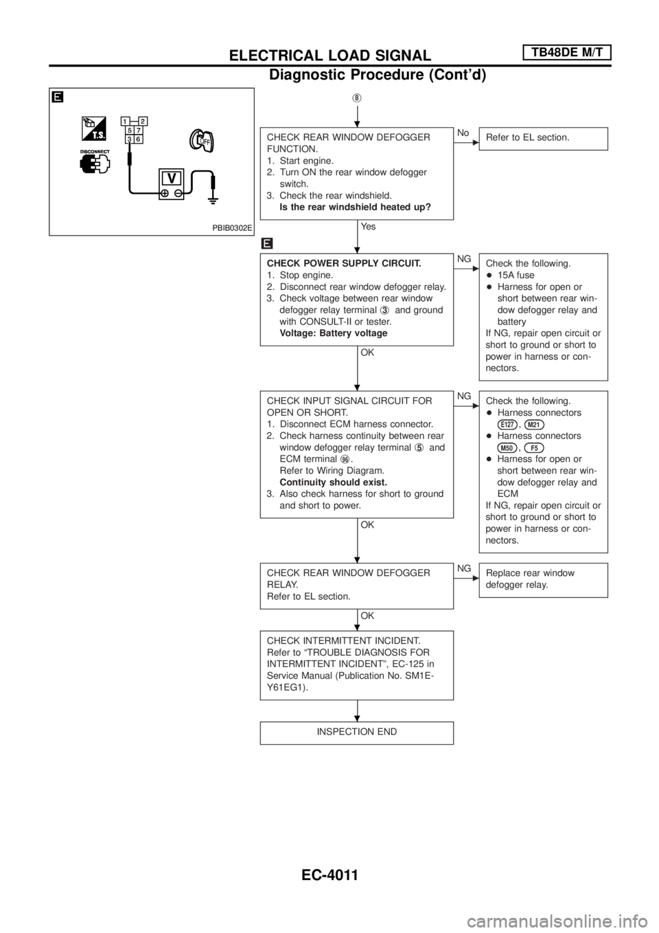
jB
CHECK REAR WINDOW DEFOGGER
FUNCTION.
1. Start engine.
2. Turn ON the rear window defogger
switch.
3. Check the rear windshield.
Is the rear windshield heated up?
Ye s
cNo
Refer to EL section.
CHECK POWER SUPPLY CIRCUIT.
1. Stop engine.
2. Disconnect rear window defogger relay.
3. Check voltage between rear window
defogger relay terminalj
3and ground
with CONSULT-II or tester.
Voltage: Battery voltage
OK
cNG
Check the following.
+15A fuse
+Harness for open or
short between rear win-
dow defogger relay and
battery
If NG, repair open circuit or
short to ground or short to
power in harness or con-
nectors.
CHECK INPUT SIGNAL CIRCUIT FOR
OPEN OR SHORT.
1. Disconnect ECM harness connector.
2. Check harness continuity between rear
window defogger relay terminalj
5and
ECM terminalj
96.
Refer to Wiring Diagram.
Continuity should exist.
3. Also check harness for short to ground
and short to power.
OK
cNG
Check the following.
+Harness connectors
E127,M21
+Harness connectors
M50,F5
+Harness for open or
short between rear win-
dow defogger relay and
ECM
If NG, repair open circuit or
short to ground or short to
power in harness or con-
nectors.
CHECK REAR WINDOW DEFOGGER
RELAY.
Refer to EL section.
OK
cNG
Replace rear window
defogger relay.
CHECK INTERMITTENT INCIDENT.
Refer to ªTROUBLE DIAGNOSIS FOR
INTERMITTENT INCIDENTº, EC-125 in
Service Manual (Publication No. SM1E-
Y61EG1).
INSPECTION END
PBIB0302E
.
.
.
.
.
.
ELECTRICAL LOAD SIGNALTB48DE M/T
Diagnostic Procedure (Cont'd)
EC-4011