2004 NISSAN PATROL EL Start
[x] Cancel search: EL StartPage 286 of 579
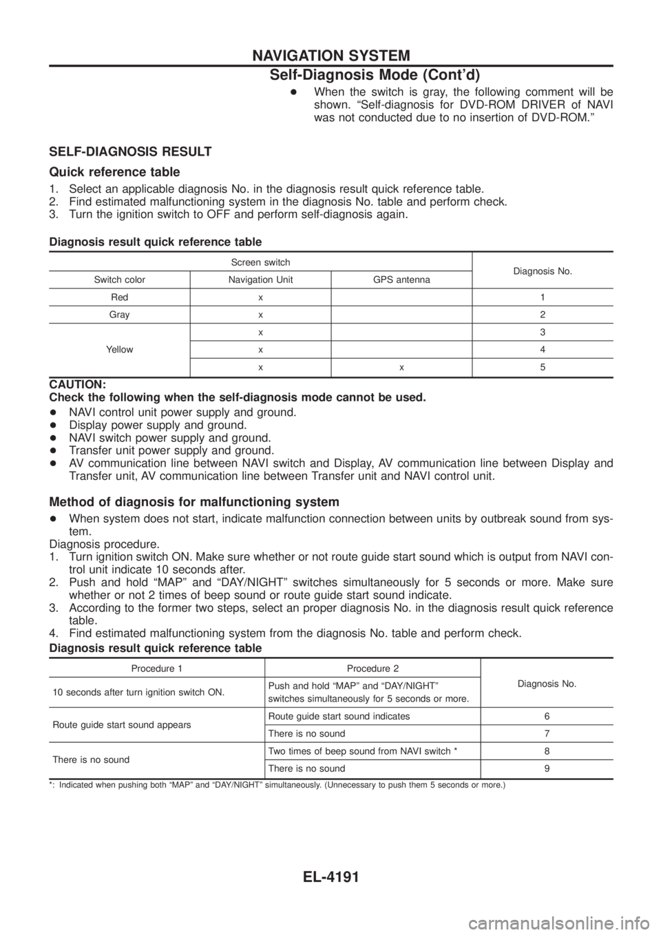
+When the switch is gray, the following comment will be
shown. ªSelf-diagnosis for DVD-ROM DRIVER of NAVI
was not conducted due to no insertion of DVD-ROM.º
SELF-DIAGNOSIS RESULT
Quick reference table
1. Select an applicable diagnosis No. in the diagnosis result quick reference table.
2. Find estimated malfunctioning system in the diagnosis No. table and perform check.
3. Turn the ignition switch to OFF and perform self-diagnosis again.
Diagnosis result quick reference table
Screen switch
Diagnosis No.
Switch color Navigation Unit GPS antenna
Red x 1
Gray x 2
Yellow x3
x4
xx5
CAUTION:
Check the following when the self-diagnosis mode cannot be used.
+
NAVI control unit power supply and ground.
+ Display power supply and ground.
+ NAVI switch power supply and ground.
+ Transfer unit power supply and ground.
+ AV communication line between NAVI switch and Display, AV communication line between Display and
Transfer unit, AV communication line between Transfer unit and NAVI control unit.
Method of diagnosis for malfunctioning system
+When system does not start, indicate malfunction connection between units by outbreak sound from sys-
tem.
Diagnosis procedure.
1. Turn ignition switch ON. Make sure whether or not route guide start sound which is output from NAVI con- trol unit indicate 10 seconds after.
2. Push and hold ªMAPº and ªDAY/NIGHTº switches simultaneously for 5 seconds or more. Make sure whether or not 2 times of beep sound or route guide start sound indicate.
3. According to the former two steps, select an proper diagnosis No. in the diagnosis result quick reference table.
4. Find estimated malfunctioning system from the diagnosis No. table and perform check.
Diagnosis result quick reference table
Procedure 1 Procedure 2
Diagnosis No.
10 seconds after turn ignition switch ON. Push and hold ªMAPº and ªDAY/NIGHTº
switches simultaneously for 5 seconds or more.
Route guide start sound appears Route guide start sound indicates 6
There is no sound 7
There is no sound Two times of beep sound from NAVI switch * 8
There is no sound 9
*: Indicated when pushing both ªMAPº and ªDAY/NIGHTº simultaneously. (Unnecessary to push them 5 seconds or more.)
NAVIGATION SYSTEM
Self-Diagnosis Mode (Cont'd)
EL-4191
Page 287 of 579
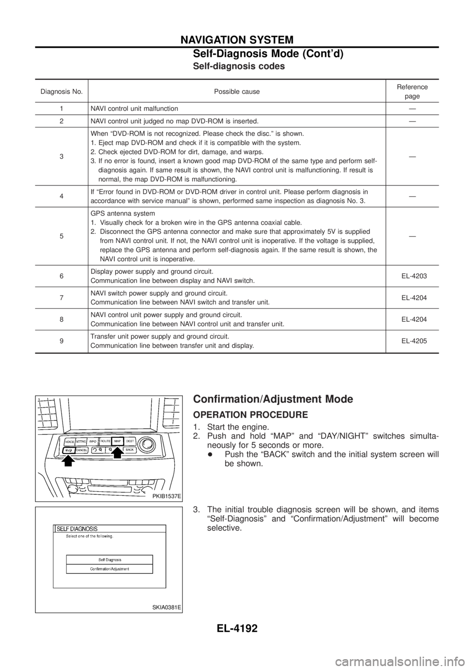
Self-diagnosis codes
Diagnosis No. Possible causeReference
page
1 NAVI control unit malfunction Ð
2 NAVI control unit judged no map DVD-ROM is inserted. Ð
3 When ªDVD-ROM is not recognized. Please check the disc.º is shown.
1. Eject map DVD-ROM and check if it is compatible with the system.
2. Check ejected DVD-ROM for dirt, damage, and warps.
3. If no error is found, insert a known good map DVD-ROM of the same type and perform self-
diagnosis again. If same result is shown, the NAVI control unit is malfunctioning. If result is
normal, the map DVD-ROM is malfunctioning. Ð
4 If ªError found in DVD-ROM or DVD-ROM driver in control unit. Please perform diagnosis in
accordance with service manualº is shown, performed same inspection as diagnosis No. 3. Ð
5 GPS antenna system
1. Visually check for a broken wire in the GPS antenna coaxial cable.
2. Disconnect the GPS antenna connector and make sure that approximately 5V is supplied
from NAVI control unit. If not, the NAVI control unit is inoperative. If the voltage is supplied,
replace the GPS antenna and perform self-diagnosis again. If the same result is shown, the
NAVI control unit is inoperative. Ð
6 Display power supply and ground circuit.
Communication line between display and NAVI switch. EL-4203
7 NAVI switch power supply and ground circuit.
Communication line between NAVI switch and transfer unit. EL-4204
8 NAVI control unit power supply and ground circuit.
Communication line between NAVI control unit and transfer unit. EL-4204
9 Transfer unit power supply and ground circuit.
Communication line between transfer unit and display. EL-4205
Con®rmation/Adjustment Mode
OPERATION PROCEDURE
1. Start the engine.
2. Push and hold ªMAPº and ªDAY/NIGHTº switches simulta-
neously for 5 seconds or more.
+ Push the ªBACKº switch and the initial system screen will
be shown.
3. The initial trouble diagnosis screen will be shown, and items ªSelf-Diagnosisº and ªCon®rmation/Adjustmentº will become
selective.
PKIB1537E
SKIA0381E
NAVIGATION SYSTEM
Self-Diagnosis Mode (Cont'd)
EL-4192
Page 292 of 579
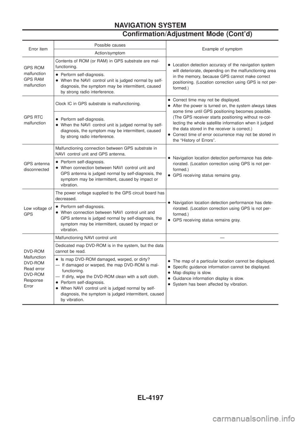
Error itemPossible causes
Example of symptom
Action/symptom
GPS ROM
malfunction
GPS RAM
malfunction Contents of ROM (or RAM) in GPS substrate are mal-
functioning.
+
Location detection accuracy of the navigation system
will deteriorate, depending on the malfunctioning area
in the memory, because GPS cannot make correct
positioning. (Location correction using GPS is not per-
formed.)
+
Perform self-diagnosis.
+ When the NAVI control unit is judged normal by self-
diagnosis, the symptom may be intermittent, caused
by strong radio interference.
GPS RTC
malfunction Clock IC in GPS substrate is malfunctioning.
+
Correct time may not be displayed.
+ After the power is turned on, the system always takes
some time until GPS positioning becomes possible.
(The GPS receiver starts positioning without re-col-
lecting the whole satellite information when it judged
the data stored in the receiver is correct.)
+ Correct time of error occurrence may not be stored in
the ªHistory of Errorsº.
+
Perform self-diagnosis.
+ When the NAVI control unit is judged normal by self-
diagnosis, the symptom may be intermittent, caused
by strong radio interference.
GPS antenna
disconnected Malfunctioning connection between GPS substrate in
NAVI control unit and GPS antenna.
+Navigation location detection performance has dete-
riorated. (Location correction using GPS is not per-
formed.)
+ GPS receiving status remains gray.
+
Perform self-diagnosis.
+ When connection between NAVI control unit and
GPS antenna is judged normal by self-diagnosis, the
symptom may be intermittent, caused by impact or
vibration.
Low voltage of
GPS The power voltage supplied to the GPS circuit board has
decreased.
+Navigation location detection performance has dete-
riorated. (Location correction using GPS is not per-
formed.)
+ GPS receiving status remains gray.
+
Perform self-diagnosis.
+ When connection between NAVI control unit and
GPS antenna is judged normal by self-diagnosis, the
symptom may be intermittent, caused by impact or
vibration.
DVD-ROM
Malfunction
DVD-ROM
Read error
DVD-ROM
Response
Error Malfunctioning NAVI control unit Ð
Dedicated map DVD-ROM is in the system, but the data
cannot be read.
+The map of a particular location cannot be displayed.
+ Speci®c guidance information cannot be displayed.
+ Map display is slow.
+ Guidance information display is slow.
+ System has been affected by vibration.
+
Is map DVD-ROM damaged, warped, or dirty?
Ð If damaged or warped, the map DVD-ROM is mal- functioning.
Ð If dirty, wipe the DVD-ROM clean with a soft cloth.
+ Perform self-diagnosis.
+ When NAVI control unit is judged normal by self-
diagnosis, the symptom is judged intermittent, caused
by vibration.
NAVIGATION SYSTEM
Con®rmation/Adjustment Mode (Cont'd)
EL-4197
Page 302 of 579

3. CHECK VEHICLE SPEED SIGNAL
1. Connect NAVI control unit and combination meter connector.
2. Start engine and drive vehicle at more than 40 km/h (25 MPH).
3. Check the signal between NAVI control unit harness connector M168 terminal 28 (R/W) and ground with CONSULT-ll oroscilloscope.
SKIA9106E
28 (R/W) - Ground: Refer to EL-4183. OK or NG
OK ©Replace NAVI control unit.
NG ©Replace uni®ed meter control unit.
ILLUMINATION SIGNAL CHECK
1. CHECK TAIL LAMP OPERATION
When lighting switch turned 1st or 2nd position, does tail lamp illuminate?
YesorNo
Ye s ©GO TO 2.
No ©Go to tail lamp trouble diagnosis.
2. CHECK ILLUMINATION SIGNAL
Check voltage between NAVI control unit and ground.
SKIB0315E
OK or NG
OK ©Replace NAVI control unit.
NG ©Repair harness or connector.
Terminals
Lighting switch position Voltage
(+)
(þ)
Connector Terminal (wire color)
M168 25 (L/B) Ground 1st or 2nd position Battery voltage
OFF Approx. 0V
NAVIGATION SYSTEM
Trouble Diagnoses (Cont'd)
EL-4207
Page 314 of 579
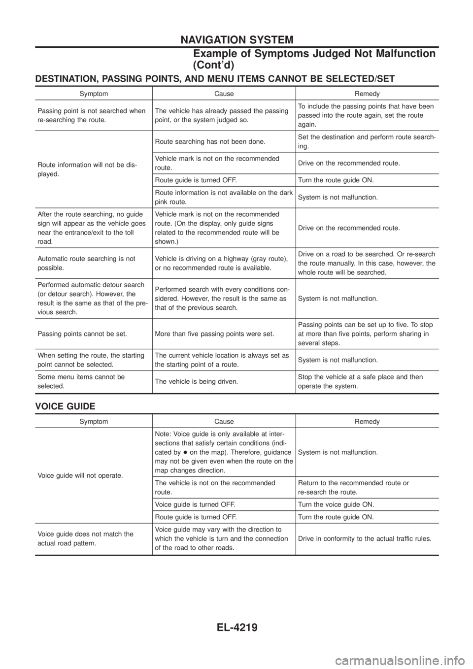
DESTINATION, PASSING POINTS, AND MENU ITEMS CANNOT BE SELECTED/SET
Symptom Cause Remedy
Passing point is not searched when
re-searching the route. The vehicle has already passed the passing
point, or the system judged so. To include the passing points that have been
passed into the route again, set the route
again.
Route information will not be dis-
played. Route searching has not been done.
Set the destination and perform route search-
ing.
Vehicle mark is not on the recommended
route. Drive on the recommended route.
Route guide is turned OFF. Turn the route guide ON.
Route information is not available on the dark
pink route. System is not malfunction.
After the route searching, no guide
sign will appear as the vehicle goes
near the entrance/exit to the toll
road. Vehicle mark is not on the recommended
route. (On the display, only guide signs
related to the recommended route will be
shown.)
Drive on the recommended route.
Automatic route searching is not
possible. Vehicle is driving on a highway (gray route),
or no recommended route is available. Drive on a road to be searched. Or re-search
the route manually. In this case, however, the
whole route will be searched.
Performed automatic detour search
(or detour search). However, the
result is the same as that of the pre-
vious search. Performed search with every conditions con-
sidered. However, the result is the same as
that of the previous search.
System is not malfunction.
Passing points cannot be set. More than ®ve passing points were set. Passing points can be set up to ®ve. To stop
at more than ®ve points, perform sharing in
several steps.
When setting the route, the starting
point cannot be selected. The current vehicle location is always set as
the starting point of a route.
System is not malfunction.
Some menu items cannot be
selected. The vehicle is being driven. Stop the vehicle at a safe place and then
operate the system.
VOICE GUIDE
Symptom Cause Remedy
Voice guide will not operate. Note: Voice guide is only available at inter-
sections that satisfy certain conditions (indi-
cated by
+on the map). Therefore, guidance
may not be given even when the route on the
map changes direction. System is not malfunction.
The vehicle is not on the recommended
route. Return to the recommended route or
re-search the route.
Voice guide is turned OFF. Turn the voice guide ON.
Route guide is turned OFF. Turn the route guide ON.
Voice guide does not match the
actual road pattern. Voice guide may vary with the direction to
which the vehicle is turn and the connection
of the road to other roads.
Drive in conformity to the actual traffic rules.
NAVIGATION SYSTEM
Example of Symptoms Judged Not Malfunction
(Cont'd)
EL-4219
Page 315 of 579
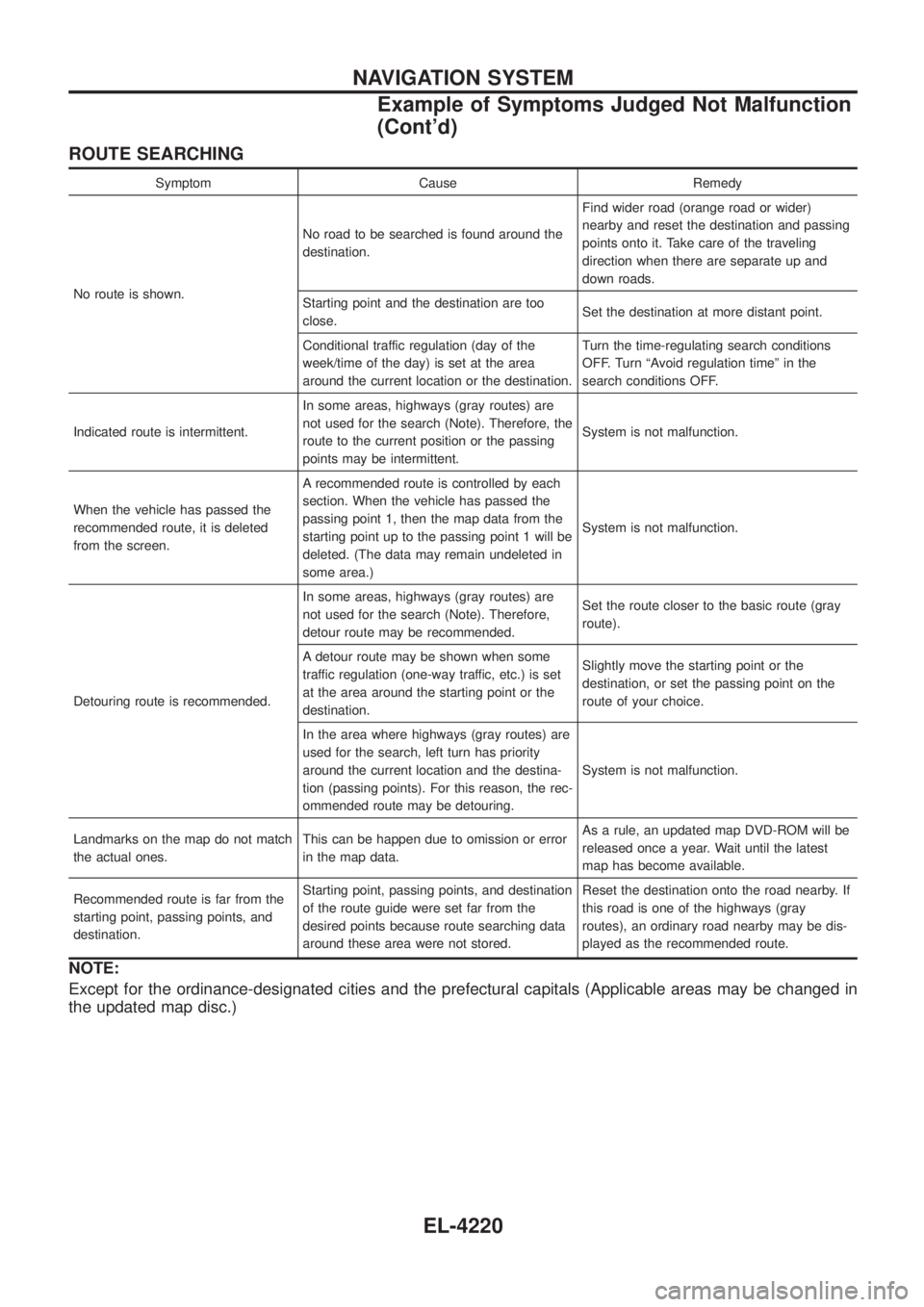
ROUTE SEARCHING
Symptom Cause Remedy
No route is shown. No road to be searched is found around the
destination.
Find wider road (orange road or wider)
nearby and reset the destination and passing
points onto it. Take care of the traveling
direction when there are separate up and
down roads.
Starting point and the destination are too
close. Set the destination at more distant point.
Conditional traffic regulation (day of the
week/time of the day) is set at the area
around the current location or the destination. Turn the time-regulating search conditions
OFF. Turn ªAvoid regulation timeº in the
search conditions OFF.
Indicated route is intermittent. In some areas, highways (gray routes) are
not used for the search (Note). Therefore, the
route to the current position or the passing
points may be intermittent. System is not malfunction.
When the vehicle has passed the
recommended route, it is deleted
from the screen. A recommended route is controlled by each
section. When the vehicle has passed the
passing point 1, then the map data from the
starting point up to the passing point 1 will be
deleted. (The data may remain undeleted in
some area.)
System is not malfunction.
Detouring route is recommended. In some areas, highways (gray routes) are
not used for the search (Note). Therefore,
detour route may be recommended.
Set the route closer to the basic route (gray
route).
A detour route may be shown when some
traffic regulation (one-way traffic, etc.) is set
at the area around the starting point or the
destination. Slightly move the starting point or the
destination, or set the passing point on the
route of your choice.
In the area where highways (gray routes) are
used for the search, left turn has priority
around the current location and the destina-
tion (passing points). For this reason, the rec-
ommended route may be detouring. System is not malfunction.
Landmarks on the map do not match
the actual ones. This can be happen due to omission or error
in the map data. As a rule, an updated map DVD-ROM will be
released once a year. Wait until the latest
map has become available.
Recommended route is far from the
starting point, passing points, and
destination. Starting point, passing points, and destination
of the route guide were set far from the
desired points because route searching data
around these area were not stored. Reset the destination onto the road nearby. If
this road is one of the highways (gray
routes), an ordinary road nearby may be dis-
played as the recommended route.
NOTE:
Except for the ordinance-designated cities and the prefectural capitals (Applicable areas may be changed in
the updated map disc.)
NAVIGATION SYSTEM
Example of Symptoms Judged Not Malfunction
(Cont'd)
EL-4220
Page 319 of 579
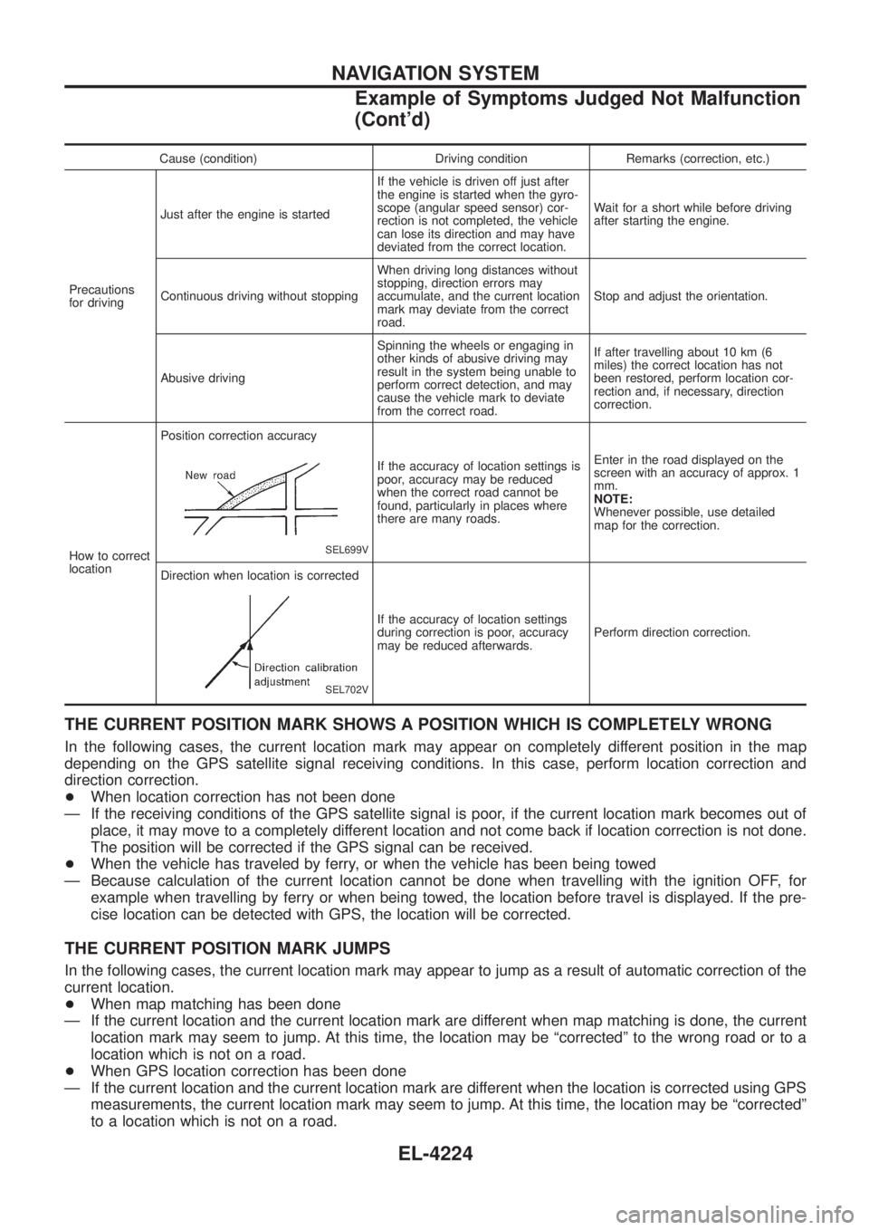
Cause (condition) Driving condition Remarks (correction, etc.)
Precautions
for driving Just after the engine is started
If the vehicle is driven off just after
the engine is started when the gyro-
scope (angular speed sensor) cor-
rection is not completed, the vehicle
can lose its direction and may have
deviated from the correct location.Wait for a short while before driving
after starting the engine.
Continuous driving without stopping When driving long distances without
stopping, direction errors may
accumulate, and the current location
mark may deviate from the correct
road.Stop and adjust the orientation.
Abusive driving Spinning the wheels or engaging in
other kinds of abusive driving may
result in the system being unable to
perform correct detection, and may
cause the vehicle mark to deviate
from the correct road.If after travelling about 10 km (6
miles) the correct location has not
been restored, perform location cor-
rection and, if necessary, direction
correction.
How to correct
location Position correction accuracy
SEL699V
If the accuracy of location settings is
poor, accuracy may be reduced
when the correct road cannot be
found, particularly in places where
there are many roads.
Enter in the road displayed on the
screen with an accuracy of approx. 1
mm.
NOTE:
Whenever possible, use detailed
map for the correction.
Direction when location is corrected
SEL702V
If the accuracy of location settings
during correction is poor, accuracy
may be reduced afterwards. Perform direction correction.
THE CURRENT POSITION MARK SHOWS A POSITION WHICH IS COMPLETELY WRONG
In the following cases, the current location mark may appear on completely different position in the map
depending on the GPS satellite signal receiving conditions. In this case, perform location correction and
direction correction.
+
When location correction has not been done
Ð If the receiving conditions of the GPS satellite signal is poor, if the current location mark becomes out of place, it may move to a completely different location and not come back if location correction is not done.
The position will be corrected if the GPS signal can be received.
+ When the vehicle has traveled by ferry, or when the vehicle has been being towed
Ð Because calculation of the current location cannot be done when travelling with the ignition OFF, for example when travelling by ferry or when being towed, the location before travel is displayed. If the pre-
cise location can be detected with GPS, the location will be corrected.
THE CURRENT POSITION MARK JUMPS
In the following cases, the current location mark may appear to jump as a result of automatic correction of the
current location.
+When map matching has been done
Ð If the current location and the current location mark are different when map matching is done, the current location mark may seem to jump. At this time, the location may be ªcorrectedº to the wrong road or to a
location which is not on a road.
+ When GPS location correction has been done
Ð If the current location and the current location mark are different when the location is corrected using GPS measurements, the current location mark may seem to jump. At this time, the location may be ªcorrectedº
to a location which is not on a road.
NAVIGATION SYSTEM
Example of Symptoms Judged Not Malfunction
(Cont'd)
EL-4224
Page 452 of 579
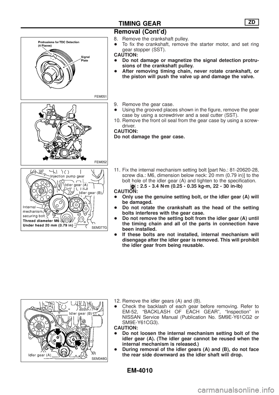
8. Remove the crankshaft pulley.
+To ®x the crankshaft, remove the starter motor, and set ring
gear stopper (SST).
CAUTION:
+Do not damage or magnetize the signal detection protru-
sions of the crankshaft pulley.
+After removing timing chain, never rotate crankshaft, or
the piston will push the valve up and damage the valve.
9. Remove the gear case.
+Using the grooved places shown in the ®gure, remove the gear
case by using a screwdriver and a seal cutter (SST).
10. Remove the front oil seal from the gear case by using a screw-
driver.
CAUTION:
Do not damage the gear case.
11. Fix the internal mechanism setting bolt [part No.: 81-20620-28,
screw dia.: M6, dimension below neck: 20 mm (0.79 in)] to the
bolt hole of the idler gear (A) and tighten to the speci®cation.
: 2.5 - 3.4 Nzm (0.25 - 0.35 kg-m, 22 - 30 in-lb)
CAUTION:
+Only use the genuine setting bolt, or the idler gear (A) will
be damaged.
+Do not rotate the crankshaft as the head of the setting
bolts interferes with the gear case.
+Do not remove the setting bolt from the idler gear (A) until
the timing chain and all of the parts in connection have
been installed.
+If these bolts are not installed, internal mechanism will
disengage after the idler gear is removed. This will prohibit
the idler gear from being reusable.
12. Remove the idler gears (A) and (B).
+Check the backlash of each gear before removing. Refer to
EM-52, ªBACKLASH OF EACH GEARº, ªInspectionº in
NISSAN Service Manual (Publication No. SM9E-Y61CG2 or
SM9E-Y61CG3).
CAUTION:
+Do not loosen the internal mechanism setting bolt of the
idler gear (A). (The idler gear cannot be reused when the
internal mechanism is released.)
+During removal of the idler gears (A) and (B), do not face
the rear side downward as the idler shaft will drop.
FEM051
FEM052
SEM377G
SEM348G
TIMING GEARZD
Removal (Cont'd)
EM-4010