2004 NISSAN PATROL turn signal
[x] Cancel search: turn signalPage 73 of 579
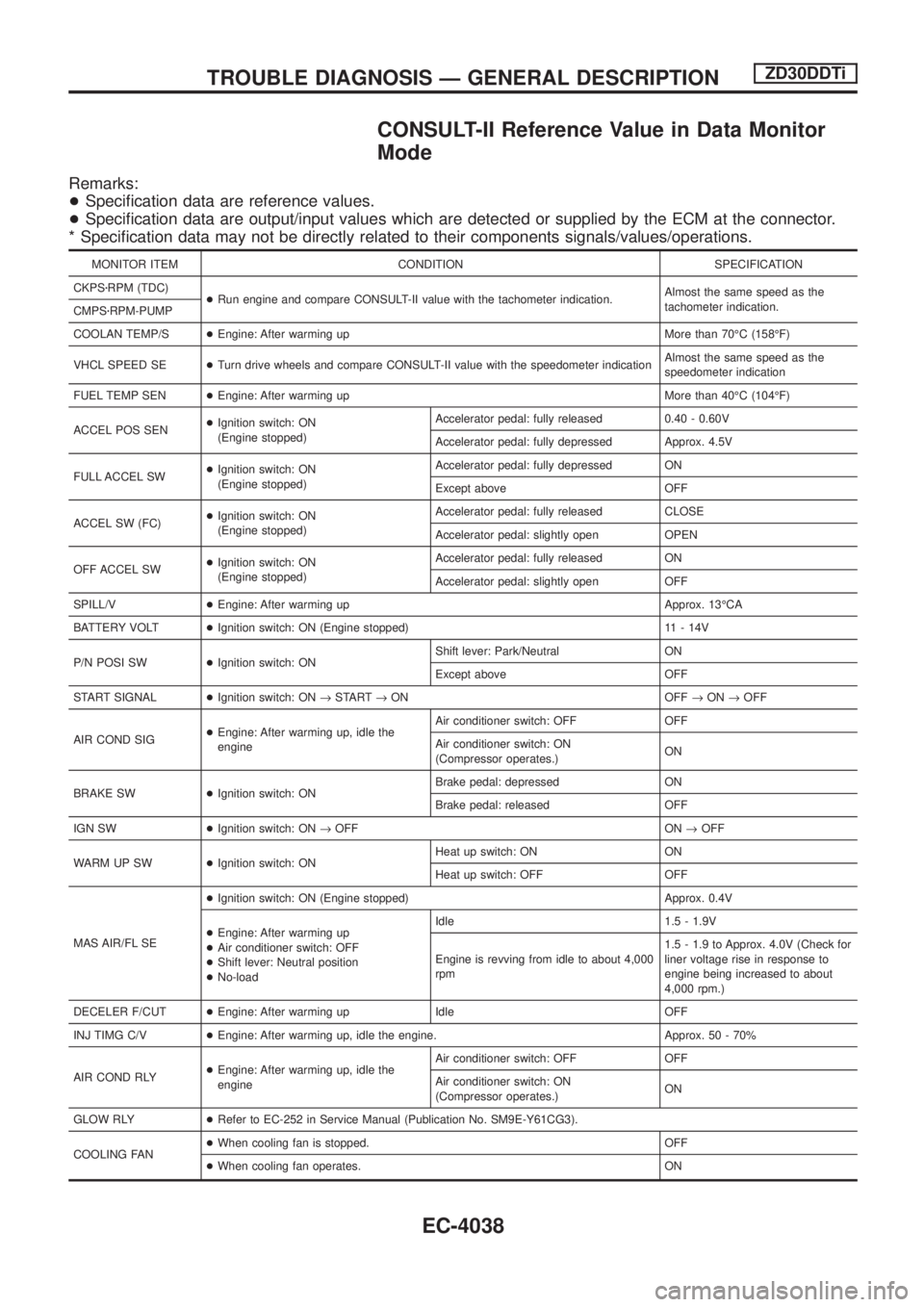
CONSULT-II Reference Value in Data Monitor
Mode
Remarks:
+Speci®cation data are reference values.
+Speci®cation data are output/input values which are detected or supplied by the ECM at the connector.
* Speci®cation data may not be directly related to their components signals/values/operations.
MONITOR ITEM CONDITION SPECIFICATION
CKPSzRPM (TDC)
+Run engine and compare CONSULT-II value with the tachometer indication.Almost the same speed as the
tachometer indication.
CMPSzRPM-PUMP
COOLAN TEMP/S+Engine: After warming up More than 70ÉC (158ÉF)
VHCL SPEED SE+Turn drive wheels and compare CONSULT-II value with the speedometer indicationAlmost the same speed as the
speedometer indication
FUEL TEMP SEN+Engine: After warming up More than 40ÉC (104ÉF)
ACCEL POS SEN+Ignition switch: ON
(Engine stopped)Accelerator pedal: fully released 0.40 - 0.60V
Accelerator pedal: fully depressed Approx. 4.5V
FULL ACCEL SW+Ignition switch: ON
(Engine stopped)Accelerator pedal: fully depressed ON
Except above OFF
ACCEL SW (FC)+Ignition switch: ON
(Engine stopped)Accelerator pedal: fully released CLOSE
Accelerator pedal: slightly open OPEN
OFF ACCEL SW+Ignition switch: ON
(Engine stopped)Accelerator pedal: fully released ON
Accelerator pedal: slightly open OFF
SPILL/V+Engine: After warming up Approx. 13ÉCA
BATTERY VOLT+Ignition switch: ON (Engine stopped) 11 - 14V
P/N POSI SW+Ignition switch: ONShift lever: Park/Neutral ON
Except above OFF
START SIGNAL+Ignition switch: ON®START®ON OFF®ON®OFF
AIR COND SIG+Engine: After warming up, idle the
engineAir conditioner switch: OFF OFF
Air conditioner switch: ON
(Compressor operates.)ON
BRAKE SW+Ignition switch: ONBrake pedal: depressed ON
Brake pedal: released OFF
IGN SW+Ignition switch: ON®OFF ON®OFF
WARM UP SW+Ignition switch: ONHeat up switch: ON ON
Heat up switch: OFF OFF
MAS AIR/FL SE+Ignition switch: ON (Engine stopped) Approx. 0.4V
+Engine: After warming up
+Air conditioner switch: OFF
+Shift lever: Neutral position
+No-loadIdle 1.5 - 1.9V
Engine is revving from idle to about 4,000
rpm1.5 - 1.9 to Approx. 4.0V (Check for
liner voltage rise in response to
engine being increased to about
4,000 rpm.)
DECELER F/CUT+Engine: After warming up Idle OFF
INJ TIMG C/V+Engine: After warming up, idle the engine. Approx. 50 - 70%
AIR COND RLY+Engine: After warming up, idle the
engineAir conditioner switch: OFF OFF
Air conditioner switch: ON
(Compressor operates.)ON
GLOW RLY+Refer to EC-252 in Service Manual (Publication No. SM9E-Y61CG3).
COOLING FAN+When cooling fan is stopped. OFF
+When cooling fan operates. ON
TROUBLE DIAGNOSIS Ð GENERAL DESCRIPTIONZD30DDTi
EC-4038
Page 75 of 579
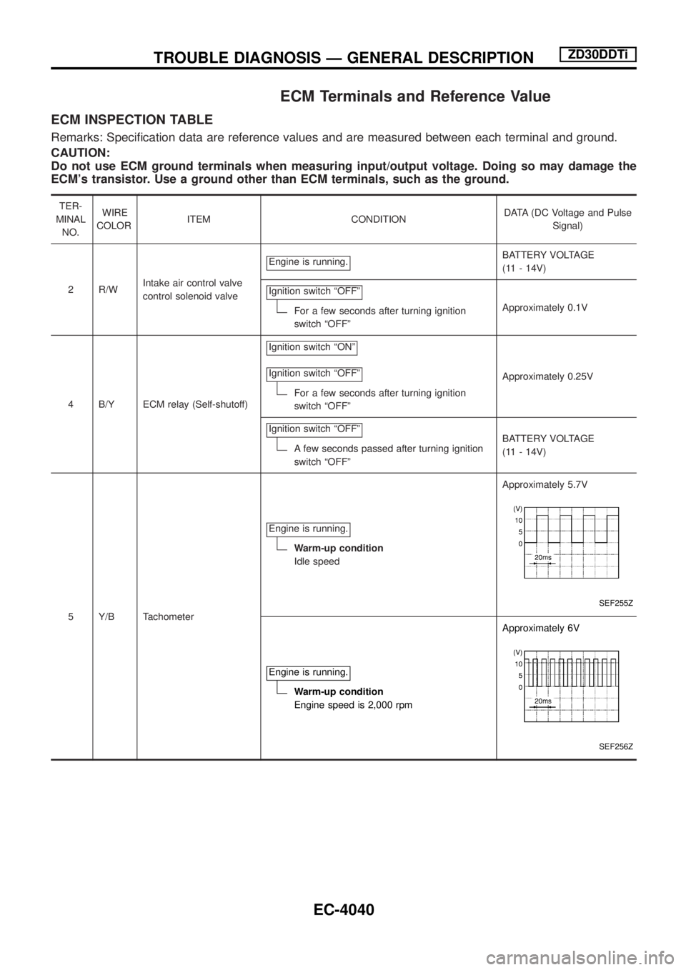
ECM Terminals and Reference Value
ECM INSPECTION TABLE
Remarks: Speci®cation data are reference values and are measured between each terminal and ground.
CAUTION:
Do not use ECM ground terminals when measuring input/output voltage. Doing so may damage the
ECM's transistor. Use a ground other than ECM terminals, such as the ground.
TER-
MINAL
NO.WIRE
COLORITEM CONDITIONDATA (DC Voltage and Pulse
Signal)
2 R/WIntake air control valve
control solenoid valveEngine is running.
BATTERY VOLTAGE
(11 - 14V)
Ignition switch ªOFFº
For a few seconds after turning ignition
switch ªOFFºApproximately 0.1V
4 B/Y ECM relay (Self-shutoff)Ignition switch ªONº
Ignition switch ªOFFº
For a few seconds after turning ignition
switch ªOFFºApproximately 0.25V
Ignition switch ªOFFº
A few seconds passed after turning ignition
switch ªOFFºBATTERY VOLTAGE
(11 - 14V)
5 Y/B TachometerEngine is running.
Warm-up condition
Idle speedApproximately 5.7V
SEF255Z
Engine is running.
Warm-up condition
Engine speed is 2,000 rpmApproximately 6V
SEF256Z
TROUBLE DIAGNOSIS Ð GENERAL DESCRIPTIONZD30DDTi
EC-4040
Page 79 of 579
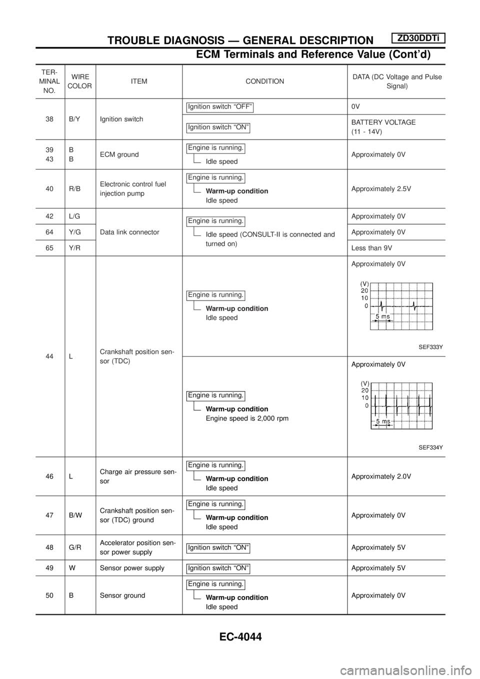
TER-
MINAL
NO.WIRE
COLORITEM CONDITIONDATA (DC Voltage and Pulse
Signal)
38 B/Y Ignition switchIgnition switch ªOFFº
0V
Ignition switch ªONº
BATTERY VOLTAGE
(11 - 14V)
39
43B
BECM groundEngine is running.
Idle speedApproximately 0V
40 R/BElectronic control fuel
injection pumpEngine is running.
Warm-up condition
Idle speedApproximately 2.5V
42 L/G
Data link connectorEngine is running.
Idle speed (CONSULT-II is connected and
turned on)Approximately 0V
64 Y/GApproximately 0V
65 Y/RLess than 9V
44 LCrankshaft position sen-
sor (TDC)Engine is running.
Warm-up condition
Idle speedApproximately 0V
SEF333Y
Engine is running.
Warm-up condition
Engine speed is 2,000 rpmApproximately 0V
SEF334Y
46 LCharge air pressure sen-
sorEngine is running.Warm-up condition
Idle speedApproximately 2.0V
47 B/WCrankshaft position sen-
sor (TDC) groundEngine is running.
Warm-up condition
Idle speedApproximately 0V
48 G/RAccelerator position sen-
sor power supplyIgnition switch ªONº
Approximately 5V
49 W Sensor power supply Ignition switch ªONº
Approximately 5V
50 B Sensor groundEngine is running.
Warm-up condition
Idle speedApproximately 0V
TROUBLE DIAGNOSIS Ð GENERAL DESCRIPTIONZD30DDTi
ECM Terminals and Reference Value (Cont'd)
EC-4044
Page 81 of 579
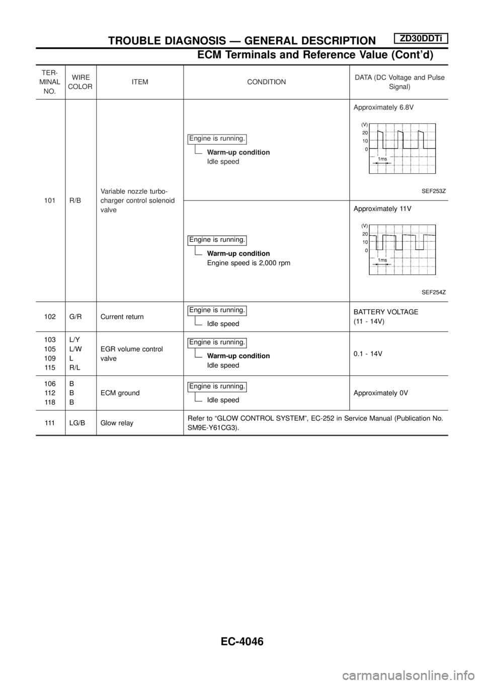
TER-
MINAL
NO.WIRE
COLORITEM CONDITIONDATA (DC Voltage and Pulse
Signal)
101 R/BVariable nozzle turbo-
charger control solenoid
valveEngine is running.
Warm-up condition
Idle speedApproximately 6.8V
SEF253Z
Engine is running.
Warm-up condition
Engine speed is 2,000 rpmApproximately 11V
SEF254Z
102 G/R Current returnEngine is running.Idle speedBATTERY VOLTAGE
(11 - 14V)
103
105
109
11 5L/Y
L/W
L
R/LEGR volume control
valveEngine is running.
Warm-up condition
Idle speed0.1 - 14V
106
11 2
11 8B
B
BECM groundEngine is running.
Idle speedApproximately 0V
111 LG/B Glow relayRefer to ªGLOW CONTROL SYSTEMº, EC-252 in Service Manual (Publication No.
SM9E-Y61CG3).
TROUBLE DIAGNOSIS Ð GENERAL DESCRIPTIONZD30DDTi
ECM Terminals and Reference Value (Cont'd)
EC-4046
Page 86 of 579
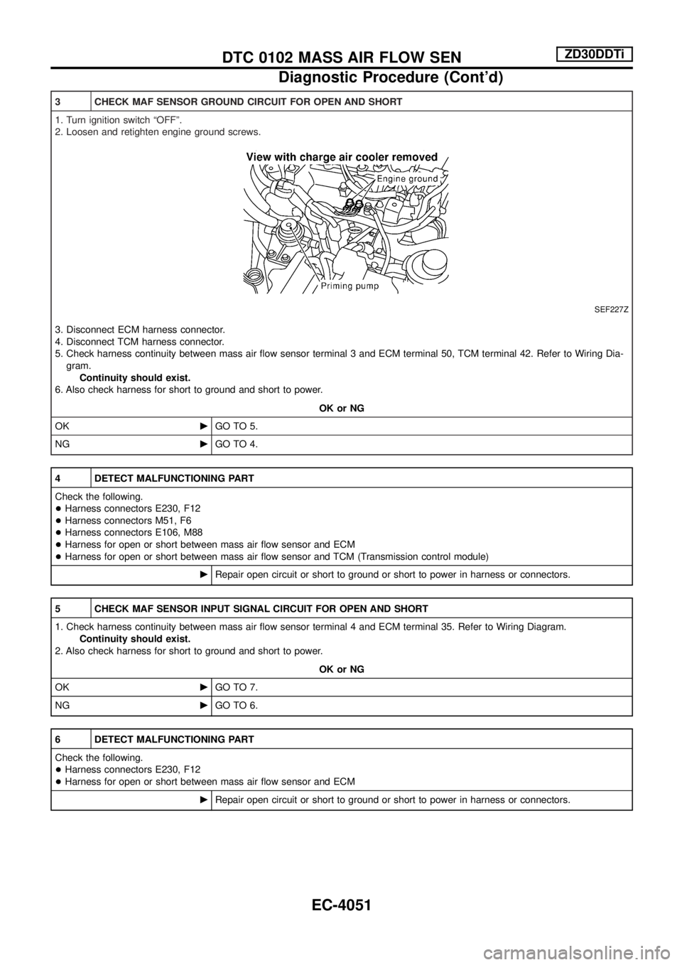
3 CHECK MAF SENSOR GROUND CIRCUIT FOR OPEN AND SHORT
1. Turn ignition switch ªOFFº.
2. Loosen and retighten engine ground screws.
SEF227Z
3. Disconnect ECM harness connector.
4. Disconnect TCM harness connector.
5. Check harness continuity between mass air ¯ow sensor terminal 3 and ECM terminal 50, TCM terminal 42. Refer to Wiring Dia-
gram.
Continuity should exist.
6. Also check harness for short to ground and short to power.
OK or NG
OKcGO TO 5.
NGcGO TO 4.
4 DETECT MALFUNCTIONING PART
Check the following.
+Harness connectors E230, F12
+Harness connectors M51, F6
+Harness connectors E106, M88
+Harness for open or short between mass air ¯ow sensor and ECM
+Harness for open or short between mass air ¯ow sensor and TCM (Transmission control module)
cRepair open circuit or short to ground or short to power in harness or connectors.
5 CHECK MAF SENSOR INPUT SIGNAL CIRCUIT FOR OPEN AND SHORT
1. Check harness continuity between mass air ¯ow sensor terminal 4 and ECM terminal 35. Refer to Wiring Diagram.
Continuity should exist.
2. Also check harness for short to ground and short to power.
OK or NG
OKcGO TO 7.
NGcGO TO 6.
6 DETECT MALFUNCTIONING PART
Check the following.
+Harness connectors E230, F12
+Harness for open or short between mass air ¯ow sensor and ECM
cRepair open circuit or short to ground or short to power in harness or connectors.
DTC 0102 MASS AIR FLOW SENZD30DDTi
Diagnostic Procedure (Cont'd)
EC-4051
Page 87 of 579
7 CHECK SHIELD CIRCUIT
1. Disconnect harness connectors E230, F12.
2. Check harness continuity between harness connector F12 terminal 5 and ground.
Refer to Wiring Diagram.
Continuity should exist.
3. Also check harness for short to power.
OK or NG
OKcGO TO 9.
NGcGO TO 8.
8 DETECT MALFUNCTIONING PART
Check the following.
+Joint connector-4
+Harness for open or short between harness connector F12 and ground
cRepair open circuit or short to power in harness or connectors.
9 CHECK MASS AIR FLOW SENSOR
1. Reconnect harness connectors disconnected.
2. Start engine and warm it up to normal operating temperature.
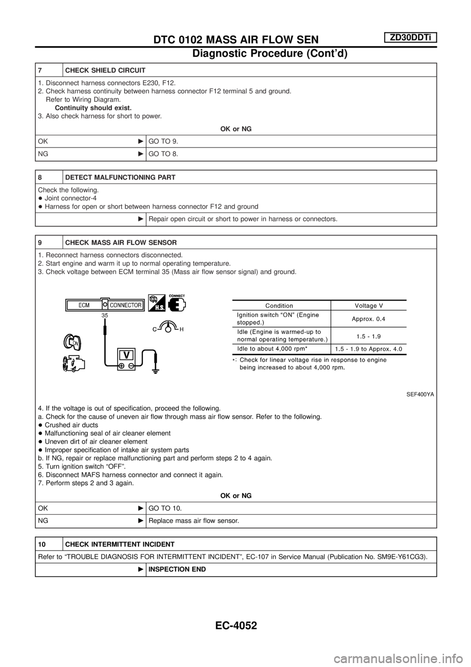
3. Check voltage between ECM terminal 35 (Mass air ¯ow sensor signal) and ground.
SEF400YA
4. If the voltage is out of speci®cation, proceed the following.
a. Check for the cause of uneven air ¯ow through mass air ¯ow sensor. Refer to the following.
+Crushed air ducts
+Malfunctioning seal of air cleaner element
+Uneven dirt of air cleaner element
+Improper speci®cation of intake air system parts
b. If NG, repair or replace malfunctioning part and perform steps 2 to 4 again.
5. Turn ignition switch ªOFFº.
6. Disconnect MAFS harness connector and connect it again.
7. Perform steps 2 and 3 again.
OK or NG
OKcGO TO 10.
NGcReplace mass air ¯ow sensor.
10 CHECK INTERMITTENT INCIDENT
Refer to ªTROUBLE DIAGNOSIS FOR INTERMITTENT INCIDENTº, EC-107 in Service Manual (Publication No. SM9E-Y61CG3).
cINSPECTION END
DTC 0102 MASS AIR FLOW SENZD30DDTi
Diagnostic Procedure (Cont'd)
EC-4052
Page 91 of 579
4 CHECK HEAT UP SWITCH POWER SUPPLY CIRCUIT
1. Turn heat up switch ªOFFº.
2. Turn ignition switch ªOFFº.
3. Disconnect heat up switch harness connector.
4. Turn ignition switch ªONº.
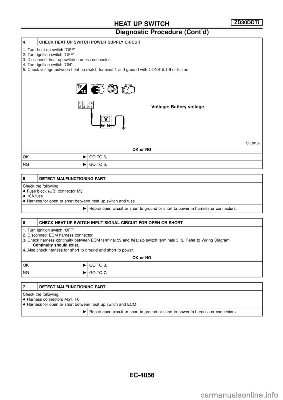
5. Check voltage between heat up switch terminal 1 and ground with CONSULT-II or tester.
SEC016E
OK or NG
OKcGO TO 6.
NGcGO TO 5.
5 DETECT MALFUNCTIONING PART
Check the following.
+Fuse block (J/B) connector M3
+10A fuse
+Harness for open or short between heat up switch and fuse
cRepair open circuit or short to ground or short to power in harness or connectors.
6 CHECK HEAT UP SWITCH INPUT SIGNAL CIRCUIT FOR OPEN OR SHORT
1. Turn ignition switch ªOFFº.
2. Disconnect ECM harness connector.
3. Check harness continuity between ECM terminal 59 and heat up switch terminals 3, 5. Refer to Wiring Diagram.
Continuity should exist.
4. Also check harness for short to ground and short to power.
OK or NG
OKcGO TO 8.
NGcGO TO 7.
7 DETECT MALFUNCTIONING PART
Check the following.
+Harness connectors M51, F6
+Harness for open or short between heat up switch and ECM
cRepair open circuit or short to ground or short to power in harness or connectors.
HEAT UP SWITCHZD30DDTi
Diagnostic Procedure (Cont'd)
EC-4056
Page 97 of 579
Wiring Diagram Ð F/FOG Ð/RHD Models for
Europe and China..................................................4062
Wiring Diagram Ð F/FOG Ð/LHD Models for
Europe ...................................................................4063
REAR FOG LAMP/WAGON AND HARDTOP
MODELS ....................................................................4064
Wiring Diagram Ð R/FOG Ð/For Europe and
China......................................................................4064
TURN SIGNAL AND HAZARD WARNING LAMPS/
WAGON AND HARDTOP MODELS .........................4067
Schematic ..............................................................4067
Wiring Diagram Ð TURN Ð/Type A .....................4068
Wiring Diagram Ð TURN Ð/Type B .....................4073
Wiring Diagram Ð TURN Ð/Type C.....................4075
Wiring Diagram Ð TURN Ð/Type D.....................4077
ILLUMINATION/WAGON AND HARDTOP
MODELS ....................................................................4079
Schematic ..............................................................4079
Wiring Diagram Ð ILL Ð ......................................4080
INTERIOR ROOM LAMP/WAGON AND HARDTOP
MODELS Ð With Timer Ð .......................................4088
Schematic/LHD Models Except for China .............4088
Wiring Diagram Ð ROOM/L Ð/LHD Models
Except for China ....................................................4089
Wiring Diagram Ð ROOM/L Ð/RHD Models for
Europe ...................................................................4092
INTERIOR ROOM LAMP/WAGON AND HARDTOP
MODELS Ð Without Timer Ð .................................4094
Wiring Diagram Ð ROOM/L Ð/RHD Models........4094
METER AND GAUGES/WAGON AND HARDTOP
MODELS ....................................................................4095
Combination Meter ................................................4095
Schematic ..............................................................4096
Wiring Diagram Ð METER Ð...............................4097
COMPASS AND THERMOMETER/WAGON AND
HARDTOP MODELS .................................................4099
Wiring Diagram Ð COMPAS Ð ............................4099
WARNING LAMPS/WAGON AND HARDTOP
MODELS ....................................................................4100
Schematic ..............................................................4100
Wiring Diagram Ð WARN Ð ................................4102
WARNING CHIME/WAGON AND HARDTOP
MODELS .................................................................... 4113
Wiring Diagram Ð CHIME Ð/Except for Europe
and with Theft Warning System Models................ 4113
Wiring Diagram Ð CHIME Ð/LHD Models for
Europe ................................................................... 4114
Wiring Diagram Ð CHIME Ð/RHD Models for
Europe ................................................................... 4115
Wiring Diagram Ð CHIME Ð/With Theft Warning
System Models ...................................................... 4116 FRONT WIPER AND WASHER/WAGON AND
HARDTOP MODELS
................................................. 4117
Wiring Diagram Ð WIPER Ð ............................... 4117
REAR WIPER AND WASHER/WAGON AND
HARDTOP MODELS ................................................. 4118
Wiring Diagram Ð WIP/R Ð ................................. 4118
HEADLAMP WASHER/WAGON AND HARDTOP
MODELS ....................................................................4122
Wiring Diagram Ð HLC Ð ....................................4122
HORN/WAGON AND HARDTOP MODELS ..............4124
Wiring Diagram Ð HORN Ð.................................4124
WIPER DEICER/WAGON AND HARDTOP
MODELS ....................................................................4125
Wiring Diagram Ð DEICER Ð..............................4125
REAR WINDOW DEFOGGER/WAGON AND
HARDTOP MODELS .................................................4126
Wiring Diagram Ð DEF Ð/LHD Models Without
Theft Warning System ...........................................4126
Wiring Diagram Ð DEF Ð/RHD Models Except
for Europe and With Theft Warning System .........4128
Wiring Diagram Ð DEF Ð/LHD Models With
Theft Warning System ...........................................4130
Wiring Diagram Ð DEF Ð/RHD Models for
Europe ...................................................................4132
Wiring Diagram Ð DEF Ð/RHD Models With
Theft Warning System ...........................................4134
AUDIO/WAGON AND HARDTOP MODELS .............4136
Schematic/LHD Models with Sub-harness ............4136
Wiring Diagram Ð AUDIO Ð/LHD Models with
Sub-harness...........................................................4137
Schematic/RHD Models with Sub-harness ...........4140
Wiring Diagram Ð AUDIO Ð/RHD Models with
Sub-harness...........................................................4141
Schematic/LHD Models without Sub-harness .......4144
Wiring Diagram Ð AUDIO Ð/LHD Models
without Sub-harness ..............................................4145
Schematic/RHD Models without Sub-harness ......4149
Wiring Diagram Ð AUDIO Ð/RHD Models
without Sub-harness ..............................................4150
Wiring Diagram Ð CD AUTO CHANGER Ð ........4154
Wiring Diagram Ð REMOTE Ð ............................4155
Wiring Diagram Ð P/ANT Ð/LHD Models............4159
Wiring Diagram Ð P/ANT Ð/RHD Models ...........4160
TELEPHONE (PRE WIRE) ........................................4161
Wiring Diagram Ð PHONE Ð ..............................4161
NAVIGATION SYSTEM .............................................4162
System Description ................................................4162
Precautions for NAVI Control Unit Replacement ..4173
Component Parts And Harness Connector
Location .................................................................4173
Schematic ..............................................................4174
Wiring Diagram Ð NAVI Ð ...................................4175
CONTENTS(Cont'd)
EL-4002