2004 NISSAN PATROL fuel pump
[x] Cancel search: fuel pumpPage 73 of 579
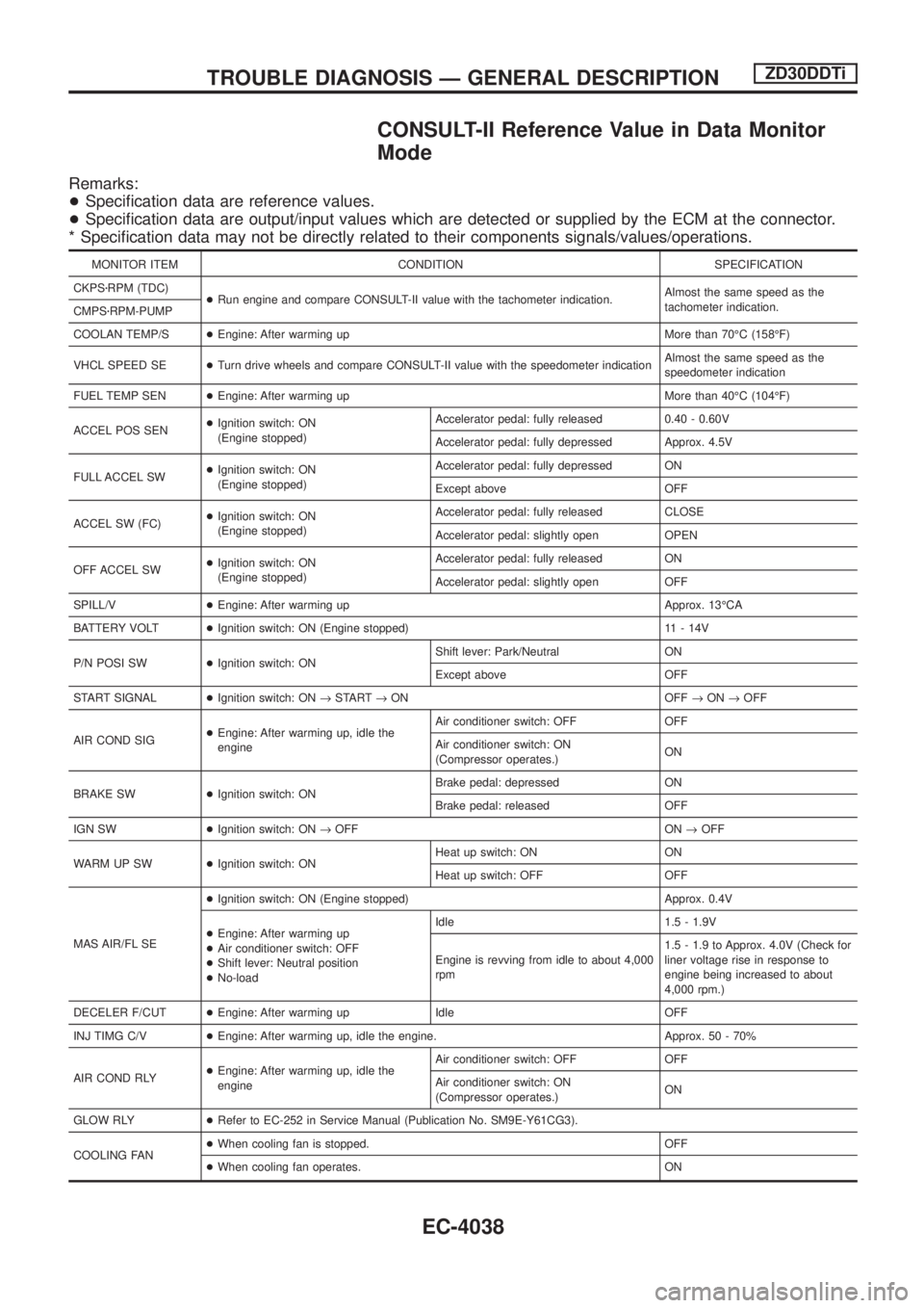
CONSULT-II Reference Value in Data Monitor
Mode
Remarks:
+Speci®cation data are reference values.
+Speci®cation data are output/input values which are detected or supplied by the ECM at the connector.
* Speci®cation data may not be directly related to their components signals/values/operations.
MONITOR ITEM CONDITION SPECIFICATION
CKPSzRPM (TDC)
+Run engine and compare CONSULT-II value with the tachometer indication.Almost the same speed as the
tachometer indication.
CMPSzRPM-PUMP
COOLAN TEMP/S+Engine: After warming up More than 70ÉC (158ÉF)
VHCL SPEED SE+Turn drive wheels and compare CONSULT-II value with the speedometer indicationAlmost the same speed as the
speedometer indication
FUEL TEMP SEN+Engine: After warming up More than 40ÉC (104ÉF)
ACCEL POS SEN+Ignition switch: ON
(Engine stopped)Accelerator pedal: fully released 0.40 - 0.60V
Accelerator pedal: fully depressed Approx. 4.5V
FULL ACCEL SW+Ignition switch: ON
(Engine stopped)Accelerator pedal: fully depressed ON
Except above OFF
ACCEL SW (FC)+Ignition switch: ON
(Engine stopped)Accelerator pedal: fully released CLOSE
Accelerator pedal: slightly open OPEN
OFF ACCEL SW+Ignition switch: ON
(Engine stopped)Accelerator pedal: fully released ON
Accelerator pedal: slightly open OFF
SPILL/V+Engine: After warming up Approx. 13ÉCA
BATTERY VOLT+Ignition switch: ON (Engine stopped) 11 - 14V
P/N POSI SW+Ignition switch: ONShift lever: Park/Neutral ON
Except above OFF
START SIGNAL+Ignition switch: ON®START®ON OFF®ON®OFF
AIR COND SIG+Engine: After warming up, idle the
engineAir conditioner switch: OFF OFF
Air conditioner switch: ON
(Compressor operates.)ON
BRAKE SW+Ignition switch: ONBrake pedal: depressed ON
Brake pedal: released OFF
IGN SW+Ignition switch: ON®OFF ON®OFF
WARM UP SW+Ignition switch: ONHeat up switch: ON ON
Heat up switch: OFF OFF
MAS AIR/FL SE+Ignition switch: ON (Engine stopped) Approx. 0.4V
+Engine: After warming up
+Air conditioner switch: OFF
+Shift lever: Neutral position
+No-loadIdle 1.5 - 1.9V
Engine is revving from idle to about 4,000
rpm1.5 - 1.9 to Approx. 4.0V (Check for
liner voltage rise in response to
engine being increased to about
4,000 rpm.)
DECELER F/CUT+Engine: After warming up Idle OFF
INJ TIMG C/V+Engine: After warming up, idle the engine. Approx. 50 - 70%
AIR COND RLY+Engine: After warming up, idle the
engineAir conditioner switch: OFF OFF
Air conditioner switch: ON
(Compressor operates.)ON
GLOW RLY+Refer to EC-252 in Service Manual (Publication No. SM9E-Y61CG3).
COOLING FAN+When cooling fan is stopped. OFF
+When cooling fan operates. ON
TROUBLE DIAGNOSIS Ð GENERAL DESCRIPTIONZD30DDTi
EC-4038
Page 78 of 579
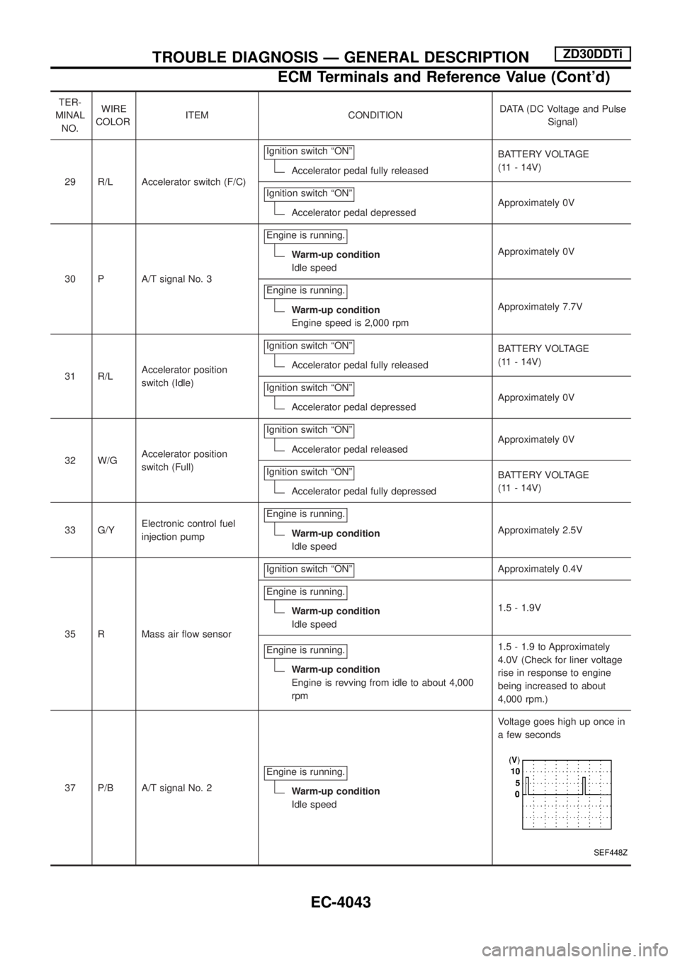
TER-
MINAL
NO.WIRE
COLORITEM CONDITIONDATA (DC Voltage and Pulse
Signal)
29 R/L Accelerator switch (F/C)Ignition switch ªONº
Accelerator pedal fully releasedBATTERY VOLTAGE
(11 - 14V)
Ignition switch ªONº
Accelerator pedal depressedApproximately 0V
30 P A/T signal No. 3Engine is running.
Warm-up condition
Idle speedApproximately 0V
Engine is running.
Warm-up condition
Engine speed is 2,000 rpmApproximately 7.7V
31 R/LAccelerator position
switch (Idle)Ignition switch ªONº
Accelerator pedal fully releasedBATTERY VOLTAGE
(11 - 14V)
Ignition switch ªONº
Accelerator pedal depressedApproximately 0V
32 W/GAccelerator position
switch (Full)Ignition switch ªONº
Accelerator pedal releasedApproximately 0V
Ignition switch ªONº
Accelerator pedal fully depressedBATTERY VOLTAGE
(11 - 14V)
33 G/YElectronic control fuel
injection pumpEngine is running.
Warm-up condition
Idle speedApproximately 2.5V
35 R Mass air ¯ow sensorIgnition switch ªONº
Approximately 0.4V
Engine is running.
Warm-up condition
Idle speed1.5 - 1.9V
Engine is running.
Warm-up condition
Engine is revving from idle to about 4,000
rpm1.5 - 1.9 to Approximately
4.0V (Check for liner voltage
rise in response to engine
being increased to about
4,000 rpm.)
37 P/B A/T signal No. 2Engine is running.
Warm-up condition
Idle speedVoltage goes high up once in
a few seconds
SEF448Z
TROUBLE DIAGNOSIS Ð GENERAL DESCRIPTIONZD30DDTi
ECM Terminals and Reference Value (Cont'd)
EC-4043
Page 79 of 579
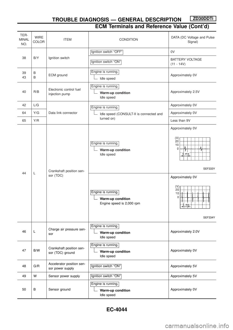
TER-
MINAL
NO.WIRE
COLORITEM CONDITIONDATA (DC Voltage and Pulse
Signal)
38 B/Y Ignition switchIgnition switch ªOFFº
0V
Ignition switch ªONº
BATTERY VOLTAGE
(11 - 14V)
39
43B
BECM groundEngine is running.
Idle speedApproximately 0V
40 R/BElectronic control fuel
injection pumpEngine is running.
Warm-up condition
Idle speedApproximately 2.5V
42 L/G
Data link connectorEngine is running.
Idle speed (CONSULT-II is connected and
turned on)Approximately 0V
64 Y/GApproximately 0V
65 Y/RLess than 9V
44 LCrankshaft position sen-
sor (TDC)Engine is running.
Warm-up condition
Idle speedApproximately 0V
SEF333Y
Engine is running.
Warm-up condition
Engine speed is 2,000 rpmApproximately 0V
SEF334Y
46 LCharge air pressure sen-
sorEngine is running.Warm-up condition
Idle speedApproximately 2.0V
47 B/WCrankshaft position sen-
sor (TDC) groundEngine is running.
Warm-up condition
Idle speedApproximately 0V
48 G/RAccelerator position sen-
sor power supplyIgnition switch ªONº
Approximately 5V
49 W Sensor power supply Ignition switch ªONº
Approximately 5V
50 B Sensor groundEngine is running.
Warm-up condition
Idle speedApproximately 0V
TROUBLE DIAGNOSIS Ð GENERAL DESCRIPTIONZD30DDTi
ECM Terminals and Reference Value (Cont'd)
EC-4044
Page 80 of 579
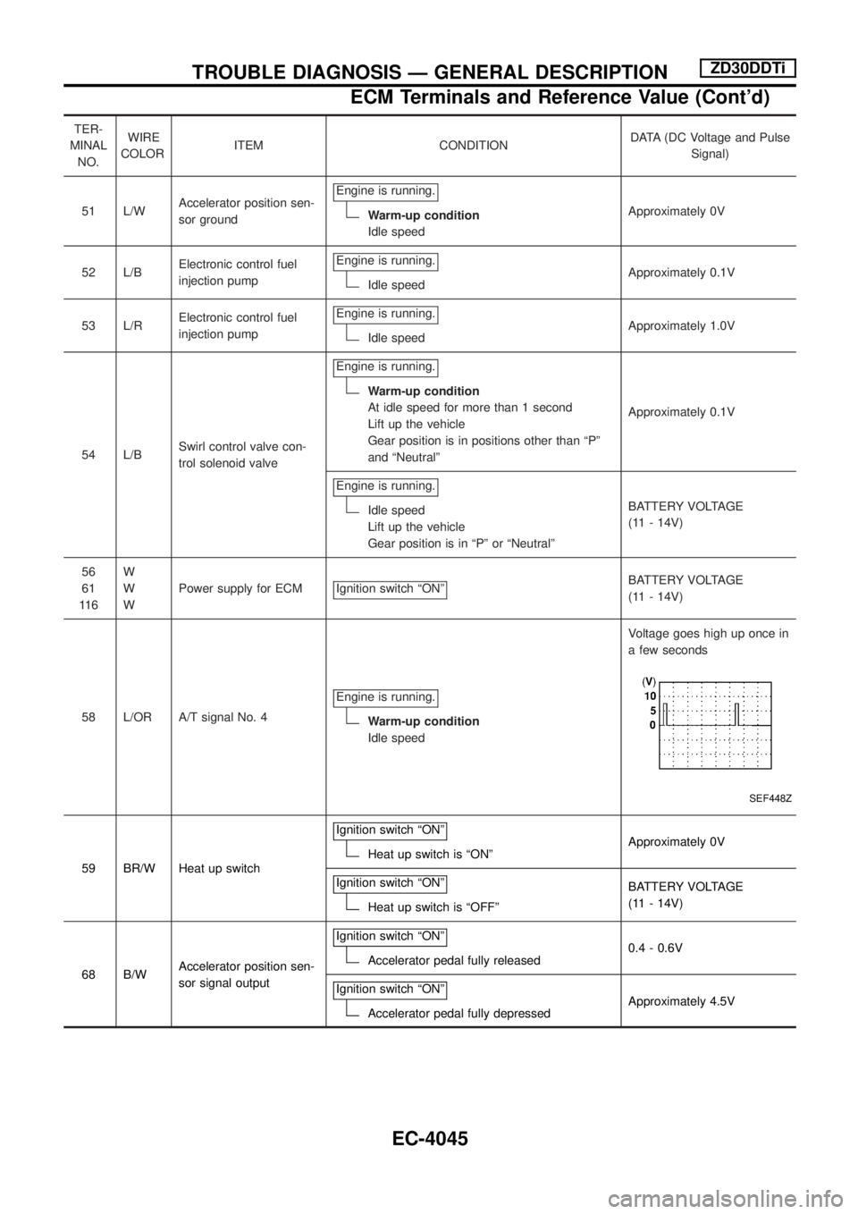
TER-
MINAL
NO.WIRE
COLORITEM CONDITIONDATA (DC Voltage and Pulse
Signal)
51 L/WAccelerator position sen-
sor groundEngine is running.
Warm-up condition
Idle speedApproximately 0V
52 L/BElectronic control fuel
injection pumpEngine is running.
Idle speedApproximately 0.1V
53 L/RElectronic control fuel
injection pumpEngine is running.
Idle speedApproximately 1.0V
54 L/BSwirl control valve con-
trol solenoid valveEngine is running.
Warm-up condition
At idle speed for more than 1 second
Lift up the vehicle
Gear position is in positions other than ªPº
and ªNeutralºApproximately 0.1V
Engine is running.
Idle speed
Lift up the vehicle
Gear position is in ªPº or ªNeutralºBATTERY VOLTAGE
(11 - 14V)
56
61
11 6W
W
WPower supply for ECM Ignition switch ªONº
BATTERY VOLTAGE
(11 - 14V)
58 L/OR A/T signal No. 4Engine is running.
Warm-up condition
Idle speedVoltage goes high up once in
a few seconds
SEF448Z
59 BR/W Heat up switchIgnition switch ªONºHeat up switch is ªONºApproximately 0V
Ignition switch ªONº
Heat up switch is ªOFFºBATTERY VOLTAGE
(11 - 14V)
68 B/WAccelerator position sen-
sor signal outputIgnition switch ªONº
Accelerator pedal fully released0.4 - 0.6V
Ignition switch ªONº
Accelerator pedal fully depressedApproximately 4.5V
TROUBLE DIAGNOSIS Ð GENERAL DESCRIPTIONZD30DDTi
ECM Terminals and Reference Value (Cont'd)
EC-4045
Page 453 of 579
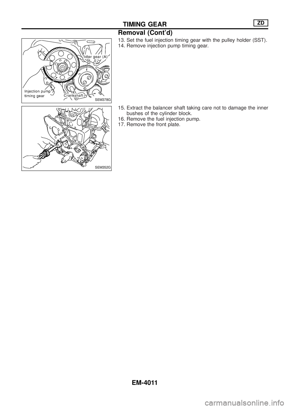
13. Set the fuel injection timing gear with the pulley holder (SST).
14. Remove injection pump timing gear.
15. Extract the balancer shaft taking care not to damage the inner
bushes of the cylinder block.
16. Remove the fuel injection pump.
17. Remove the front plate.
SEM378G
SEM352G
TIMING GEARZD
Removal (Cont'd)
EM-4011
Page 454 of 579
Installation
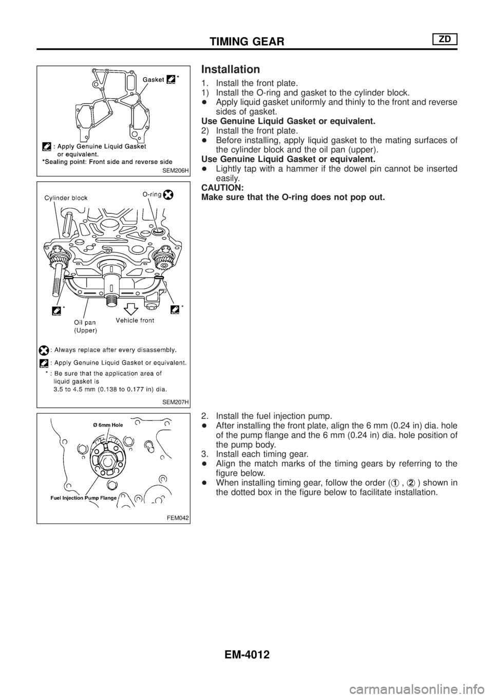
1. Install the front plate.
1) Install the O-ring and gasket to the cylinder block.
+Apply liquid gasket uniformly and thinly to the front and reverse
sides of gasket.
Use Genuine Liquid Gasket or equivalent.
2) Install the front plate.
+Before installing, apply liquid gasket to the mating surfaces of
the cylinder block and the oil pan (upper).
Use Genuine Liquid Gasket or equivalent.
+Lightly tap with a hammer if the dowel pin cannot be inserted
easily.
CAUTION:
Make sure that the O-ring does not pop out.
2. Install the fuel injection pump.
+After installing the front plate, align the 6 mm (0.24 in) dia. hole
of the pump ¯ange and the 6 mm (0.24 in) dia. hole position of
the pump body.
3. Install each timing gear.
+Align the match marks of the timing gears by referring to the
®gure below.
+When installing timing gear, follow the order (j
1,j2) shown in
the dotted box in the ®gure below to facilitate installation.
SEM206H
SEM207H
FEM042
TIMING GEARZD
EM-4012
Page 461 of 579
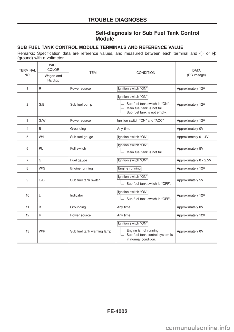
Self-diagnosis for Sub Fuel Tank Control
Module
SUB FUEL TANK CONTROL MODULE TERMINALS AND REFERENCE VALUE
Remarks: Speci®cation data are reference values, and measured between each terminal andj11orj4
(ground) with a voltmeter.
TERMINAL
NO.WIRE
COLOR
ITEM CONDITIONDATA
(DC voltage)
Wagon and
Hardtop
1 R Power source Ignition switch ªONº
Approximately 12V
2 G/B Sub fuel pumpIgnition switch ªONº
Sub fuel tank switch is ªONº.
Main fuel tank is not full.
Sub fuel tank is not empty.Approximately 12V
3 G/W Power source Ignition switch ªONº and ªACCº Approximately 12V
4 B Grounding Any time Approximately 0V
5 W/L Sub fuel gauge Ignition switch ªONº
Approximately0-4V
6 PU Full switchIgnition switch ªONº
Main fuel tank is not full.Approximately 5V
7 G Fuel gauge Ignition switch ªONº
Approximately 0 - 2.5V
8 W/G Engine running Engine running
Approximately 12V
9 G/B Sub fuel tank switchIgnition switch ªONº
Sub fuel tank switch is ªOFFº.Approximately 5V
10 L IndicatorIgnition switch ªONº
Sub fuel tank switch is ªOFFº.Approximately 12V
11 B Grounding Any time Approximately 0V
12 R Power source Any time Approximately 12V
13 W/R Sub fuel tank warning lampIgnition switch ªONº
Engine is not running.
Sub fuel tank control system is
in normal condition.Approximately 0V
TROUBLE DIAGNOSES
FE-4002