2004 NISSAN PATROL sensor
[x] Cancel search: sensorPage 519 of 579
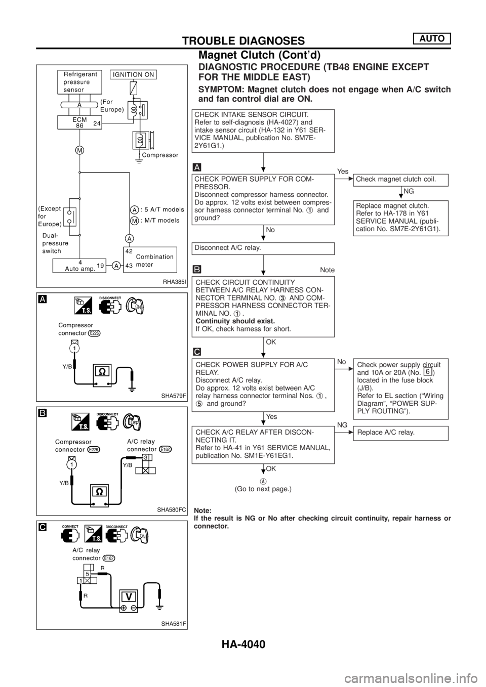
DIAGNOSTIC PROCEDURE (TB48 ENGINE EXCEPT
FOR THE MIDDLE EAST)
SYMPTOM: Magnet clutch does not engage when A/C switch
and fan control dial are ON.
CHECK INTAKE SENSOR CIRCUIT.
Refer to self-diagnosis (HA-4027) and
intake sensor circuit (HA-132 in Y61 SER-
VICE MANUAL, publication No. SM7E-
2Y61G1.)
CHECK POWER SUPPLY FOR COM-
PRESSOR.
Disconnect compressor harness connector.
Do approx. 12 volts exist between compres-
sor harness connector terminal No.j
1and
ground?
No
cYe s
Check magnet clutch coil.
NG
Replace magnet clutch.
Refer to HA-178 in Y61
SERVICE MANUAL (publi-
cation No. SM7E-2Y61G1).
Disconnect A/C relay.
Note
CHECK CIRCUIT CONTINUITY
BETWEEN A/C RELAY HARNESS CON-
NECTOR TERMINAL NO.j
3AND COM-
PRESSOR HARNESS CONNECTOR TER-
MINAL NO.j
1.
Continuity should exist.
If OK, check harness for short.
OK
CHECK POWER SUPPLY FOR A/C
RELAY.
Disconnect A/C relay.
Do approx. 12 volts exist between A/C
relay harness connector terminal Nos.j
1,
j5and ground?
Ye s
cNo
Check power supply circuit
and 10A or 20A (No.
)
located in the fuse block
(J/B).
Refer to EL section (ªWiring
Diagramº, ªPOWER SUP-
PLY ROUTINGº).
CHECK A/C RELAY AFTER DISCON-
NECTING IT.
Refer to HA-41 in Y61 SERVICE MANUAL,
publication No. SM1E-Y61EG1.
OK
cNG
Replace A/C relay.
jA(Go to next page.)
Note:
If the result is NG or No after checking circuit continuity, repair harness or
connector.
RHA385I
SHA579F
SHA580FC
SHA581F
.
.
.
.
.
.
.
TROUBLE DIAGNOSESAUTO
Magnet Clutch (Cont'd)
HA-4040
Page 520 of 579
jA
Reconnect A/C relay.
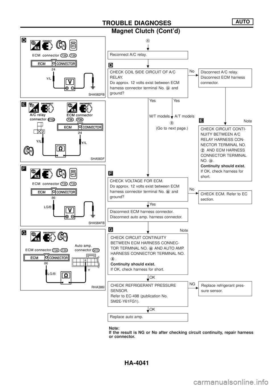
CHECK COIL SIDE CIRCUIT OF A/C
RELAY.
Do approx. 12 volts exist between ECM
harness connector terminal No.j
24and
ground?
Ye s
Ye s
cNo
Disconnect A/C relay.
Disconnect ECM harness
connector.
jB
(Go to next page.)
Note
CHECK CIRCUIT CONTI-
NUITY BETWEEN A/C
RELAY HARNESS CON-
NECTOR TERMINAL NO.
j
2AND ECM HARNESS
CONNECTOR TERMINAL
NO.j
24.
Continuity should exist.
If OK, check harness for
short.
M/T models A/T models
CHECK VOLTAGE FOR ECM.
Do approx. 12 volts exist between ECM
harness connector terminal No.j
86and
ground?
Ye s
cNo
CHECK ECM. Refer to EC
section.
Disconnect ECM harness connector.
Disconnect auto amp. harness connector.
Note
CHECK CIRCUIT CONTINUITY
BETWEEN ECM HARNESS CONNEC-
TOR TERMINAL NO.j
86AND AUTO AMP.
HARNESS CONNECTOR TERMINAL NO.
j
4.
Continuity should exist.
If OK, check harness for short.
OK
CHECK REFRIGERANT PRESSURE
SENSOR.
Refer to EC-498 (publication No.
SM2E-Y61FG1).
OK
cNG
Replace refrigerant pres-
sure sensor.
Replace auto amp.
Note:
If the result is NG or No after checking circuit continuity, repair harness
or connector.
SHA582FB
SHA583F
SHA584FB
RHA386I
.
.
.
.
.
.
.
.
.
TROUBLE DIAGNOSESAUTO
Magnet Clutch (Cont'd)
HA-4041
Page 521 of 579
jB
Note
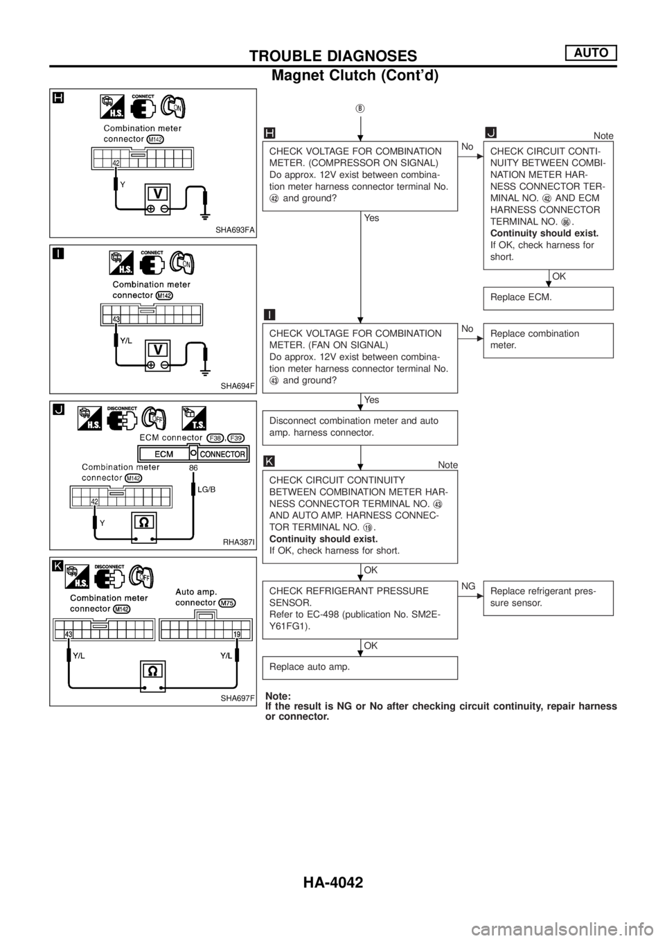
CHECK VOLTAGE FOR COMBINATION
METER. (COMPRESSOR ON SIGNAL)
Do approx. 12V exist between combina-
tion meter harness connector terminal No.
j
42and ground?
Ye s
cNo
CHECK CIRCUIT CONTI-
NUITY BETWEEN COMBI-
NATION METER HAR-
NESS CONNECTOR TER-
MINAL NO.j
42AND ECM
HARNESS CONNECTOR
TERMINAL NO.j
86.
Continuity should exist.
If OK, check harness for
short.
OK
Replace ECM.
CHECK VOLTAGE FOR COMBINATION
METER. (FAN ON SIGNAL)
Do approx. 12V exist between combina-
tion meter harness connector terminal No.
j
43and ground?
Ye s
cNo
Replace combination
meter.
Disconnect combination meter and auto
amp. harness connector.
Note
CHECK CIRCUIT CONTINUITY
BETWEEN COMBINATION METER HAR-
NESS CONNECTOR TERMINAL NO.j
43
AND AUTO AMP. HARNESS CONNEC-
TOR TERMINAL NO.j
19.
Continuity should exist.
If OK, check harness for short.
OK
CHECK REFRIGERANT PRESSURE
SENSOR.
Refer to EC-498 (publication No. SM2E-
Y61FG1).
OK
cNG
Replace refrigerant pres-
sure sensor.
Replace auto amp.
Note:
If the result is NG or No after checking circuit continuity, repair harness
or connector.
SHA693FA
SHA694F
RHA387I
SHA697F
.
.
.
.
.
.
.
TROUBLE DIAGNOSESAUTO
Magnet Clutch (Cont'd)
HA-4042
Page 547 of 579
A
A/C operational check ................................HA-4032
A/C self-diagnoses (auto A/C)....................HA-4025
A/C, A - Wiring diagram .............................HA-4009
A/CCUT - Wiring diagram ..........................EC-4058
Air cleaner ®lter replacement .....................MA-4003
Air ¯ow meter - See Mass air ¯ow
sensor .....................................................EC-4047
Air mix. door motor.....................................HA-4036
Antenna .......................................................EL-4164
ASCD (automatic speed control
device) .....................................................EL-4233
ASCD - Wiring diagram ..............................EL-4234
A/T - Wiring diagram ...................................AT-4003
A/T trouble diagnoses .................................AT-4011
A/T Wiring diagram AT - NONDTC .............AT-4012
Audio ...........................................................EL-4136
AUDIO - Wiring diagram .............................EL-4137
Audio and A/C control removal and
installation - See Instrument panel .........BT-4006
Auto air conditioner - Wiring diagram ........HA-4009
Automatic speed control system - See
ASCD ......................................................EL-4233
AV and NAVI control unit ............................EL-4164
B
Back-up lamp ..............................................EL-4055
BACK/L - Wiring diagram............................EL-4055
Blower motor ..............................................HA-4038
Bumper, front ..............................................BT-4002
Bumper, rear ...............................................BT-4005
C
Camshaft ....................................................EM-4003
CHIME - Wiring diagram .............................EL-4113
Combination meter......................................EL-4095
Combination meter removal and instal-
lation - See Instrument panel..................BT-4006
Combination switch .....................................EL-4034
COMPAS - Wiring diagram .........................EL-4099
Console box - See Instrument panel ..........BT-4006
CONSULT-II general information.................GI-4002
Cruise control - See ASCD .........................EL-4233
Cylinder head .............................................EM-4016
D
Daytime light system...................................EL-4047
DEF - Wiring diagram .................................EL-4126
DEICER - Wiring diagram...........................EL-4125
Dimensions ..................................................GI-4008
D/LOCK - Wiring diagram ...........................EL-4245Dome light - See Interior lamp ...................EL-4088
DTRL - Wiring diagram ...............................EL-4047
E
ECM input/output signal .............................EC-4040
Electrical load signal circuit ...EC-4008, 4016, 4025
Electrical units location ...............................EL-4300
Engine control circuit
diagram .............................EC-4003, 4005, 4013,
4022, 4037, 4059
Exhaust system ..........................................FE-4008
Exterior ........................................................BT-4009
F
F/FOG - Wiring diagram .............................EL-4061
FICD - Wiring diagram ...............................EC-4036
Fog lamp, front............................................EL-4061
Fog lamp, rear ............................................EL-4064
Front bumper ..............................................BT-4002
Front fog lamp.............................................EL-4061
Front washer ...............................................EL-4117
Front wiper ..................................................EL-4117
Fuel gauge ..................................................EL-4095
Fuse ..............................................................Foldout
Fusible link....................................................Foldout
G
Gauges........................................................EL-4095
GLOW - Wiring diagram.............................EC-4033
GPS antenna ..............................................EL-4164
Ground distribution......................................EL-4016
H
Harness layout ..................................EL-4307, 4308
Headlamp ....................................................EL-4040
Headlamp washer .......................................EL-4122
Heat up switch............................................EC-4054
Heated seat.................................................EL-4231
HEATUP - Wiring diagram .........................EC-4054
Height (Dimensions) ....................................GI-4008
H/LAMP - Wiring diagram ...........................EL-4040
HLC - Wiring diagram .................................EL-4122
Hood............................................................BT-4002
Horn ............................................................EL-4124
HORN - Wiring diagram..............................EL-4124
HSEAT - Wiring diagram.............................EL-4231
I
ILL - Wiring diagram ...................................EL-4080
ALPHABETICAL INDEX
IDX-4002
Page 548 of 579
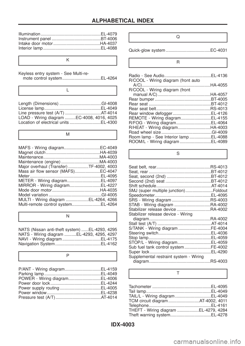
Illumination ..................................................EL-4079
Instrument panel .........................................BT-4006
Intake door motor .......................................HA-4037
Interior lamp ................................................EL-4088
K
Keyless entry system - See Multi-re-
mote control system ................................EL-4264
L
Length (Dimensions) ...................................GI-4008
License lamp ...............................................EL-4049
Line pressure test (A/T) ..............................AT-4014
LOAD - Wiring diagram .........EC-4008, 4016, 4025
Location of electrical units ..........................EL-4300
M
MAFS - Wiring diagram..............................EC-4049
Magnet clutch .............................................HA-4039
Maintenance...............................................MA-4003
Maintenance (engine) ................................MA-4003
Major overhaul (Transfer) .................TF-4002, 4003
Mass air ¯ow sensor (MAFS).....................EC-4047
Meter ...........................................................EL-4095
METER - Wiring diagram............................EL-4097
MIRROR - Wiring diagram..........................EL-4227
Mode door motor ........................................HA-4035
Model variation ............................................GI-4005
MULTI - Wiring diagram ...................EL-4264, 4266
Multi-remote control system........................EL-4264
N
NATS (Nissan anti-theft system) ......EL-4293, 4295
NATS - Wiring diagram ..........EL-4293, 4295, 4297
NAVI - Wiring diagram ................................EL-4175
Navigation System ......................................EL-4162
P
P/ANT - Wiring diagram..............................EL-4159
Parking lamp ...............................................EL-4049
POWER - Wiring diagram...........................EL-4006
Power door lock ..........................................EL-4244
Power supply routing ..................................EL-4005
Power window .............................................EL-4238
Pressure test (A/T) ......................................AT-4014Q
Quick-glow system .....................................EC-4031
R
Radio - See Audio.......................................EL-4136
R/COOL - Wiring diagram (front auto
A/C).........................................................HA-4055
R/COOL - Wiring diagram (front
manual A/C) ............................................HA-4057
Rear bumper ...............................................BT-4005
Rear seat ....................................................BT-4012
Rear seat belt .............................................RS-4013
Rear window defogger ................................EL-4126
REMOTE - Wiring diagram .........................EL-4155
R/FOG - Wiring diagram .............................EL-4064
R/HEAT - Wiring diagram ...........................HA-4003
Road wheel size ..........................................GI-4009
Room lamp - See Interior lamp ..................EL-4088
ROOM/L - Wiring diagram ..........................EL-4089
S
Seat belt, rear.............................................RS-4013
Seat, rear ....................................................BT-4012
Seat, second (2nd) .....................................BT-4012
Second (2nd) seat ......................................BT-4012
Shift schedule..............................................AT-4014
SMJ (super multiple junction) .......................Foldout
Speedometer...............................................EL-4095
SRS - Wiring diagram ................................RS-4003
STAB - Wiring diagram ..............................RA-4002
Stabilizer release device ............................RA-4002
Stabilizer release device - Wiring
diagram ...................................................RA-4002
Stall test (A/T) .............................................AT-4014
S/TANK - Wiring diagram ...........................FE-4004
Steering switch............................................EL-4036
Stop lamp ....................................................EL-4059
STOP/L - Wiring diagram............................EL-4059
Sub fuel tank control system ......................FE-4002
Super lock ...................................................EL-4290
Supplemental restraint system - Wiring
diagram ...................................................RS-4003
T
Tachometer .................................................EL-4095
Tail lamp ......................................................EL-4049
TAIL/L - Wiring diagram ..............................EL-4049
TCM circuit diagram ..........................AT-4002, 4011
Telephone....................................................EL-4161
THEFT - Wiring diagram ..................EL-4279, 4284
Theft warning system..................................EL-4278
ALPHABETICAL INDEX
IDX-4003
Page 549 of 579
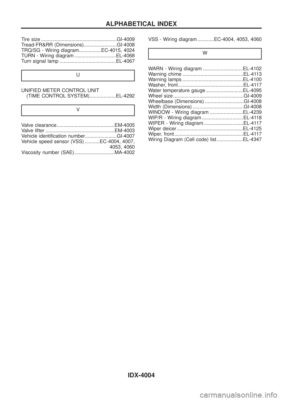
Tire size .......................................................GI-4009
Tread-FR&RR (Dimensions)........................GI-4008
TRQ/SG - Wiring diagram................EC-4015, 4024
TURN - Wiring diagram ..............................EL-4068
Turn signal lamp .........................................EL-4067
U
UNIFIED METER CONTROL UNIT
(TIME CONTROL SYSTEM) ...................EL-4292
V
Valve clearance..........................................EM-4005
Valve lifter ..................................................EM-4003
Vehicle identi®cation number.......................GI-4007
Vehicle speed sensor (VSS) ...........EC-4004, 4007,
4053, 4060
Viscosity number (SAE) .............................MA-4002VSS - Wiring diagram ............EC-4004, 4053, 4060
W
WARN - Wiring diagram .............................EL-4102
Warning chime ............................................EL-4113
Warning lamps ............................................EL-4100
Washer, front ...............................................EL-4117
Water temperature gauge ...........................EL-4095
Wheel size ...................................................GI-4009
Wheelbase (Dimensions) ............................GI-4008
Width (Dimensions) .....................................GI-4008
WINDOW - Wiring diagram ........................EL-4239
WIP/R - Wiring diagram ..............................EL-4118
WIPER - Wiring diagram.............................EL-4117
Wiper deicer ................................................EL-4125
Wiper, front ..................................................EL-4117
Wiring Diagram (Cell code) list ...................EL-4347
ALPHABETICAL INDEX
IDX-4004