2004 NISSAN PATROL sensor
[x] Cancel search: sensorPage 320 of 579
THE CURRENT LOCATION MARK IS IN A RIVER OR THE SEA
The navigation system moves the current location mark with no distinction between land and rivers or sea. If
the location mark is somehow out of place, it may appear that the vehicle is driving in a river or the sea.
WHEN DRIVING ON THE SAME ROAD, SOMETIMES THE CURRENT LOCATION MARK IS IN
THE RIGHT PLACE AND SOMETIMES IT IS THE WRONG PLACE
The conditions of the GPS antenna (GPS data) and gyroscope (angular speed sensor) change gradually.
Depending on the road traveled and the operation of the steering wheel, the location detection results will be
different. Therefore, even on a road on which the location has never been wrong, conditions may cause the
vehicle mark to deviate.
LOCATION CORRECTION BY MAP MATCHING IS SLOW
+The map matching function needs to refer to the data of the surrounding area. It is necessary to drive some
distance for the function to work.
+ Because map matching operates on this principle, when there are many roads running in similar direc-
tions in the surrounding area, no matching determination may be made. The location may not be corrected
until some special feature is found.
ALTHOUGH THE GPS RECEIVING DISPLAY IS GREEN, THE VEHICLE MARK DOES NOT
RETURN TO THE CORRECT LOCATION
+The GPS accuracy has an error of about 10 m (30 ft). In some cases the current location mark may not
be on the correct street, even when GPS location correction is done.
+ The navigation system compares the results of GPS location detection with the results from map-match-
ing location detection. The one which is determined to have higher accuracy is used.
+ GPS location correction may not be performed when the vehicle is stopped.
THE NAME OF THE CURRENT PLACE IS NOT DISPLAYED
The current place name may not be displayed if there are no place names displayed on the map screen.
CONTENTS OF THE DISPLAY DIFFER FOR THE BIRDVIEW TAND THE (FLAT) MAP SCREEN
Difference of the BIRDVIEW Tscreen from the ¯at map screen are as follows.
+ The current place name displays names which are primarily in the direction of vehicle travel.
+ The amount of time before the vehicle travel or turn angle is updated on the screen is longer than for the
(¯at) map display.
+ The conditions for display of place names, roads, and other data are different for nearby areas and for
more distant areas.
+ Some thinning of the character data is done to prevent the display becoming to complex. In some cases
and in some locations, the display contents may differ.
+ The same place name, street name, etc. may be displayed multiple times.
NAVIGATION SYSTEM
Example of Symptoms Judged Not Malfunction
(Cont'd)
EL-4225
Page 442 of 579
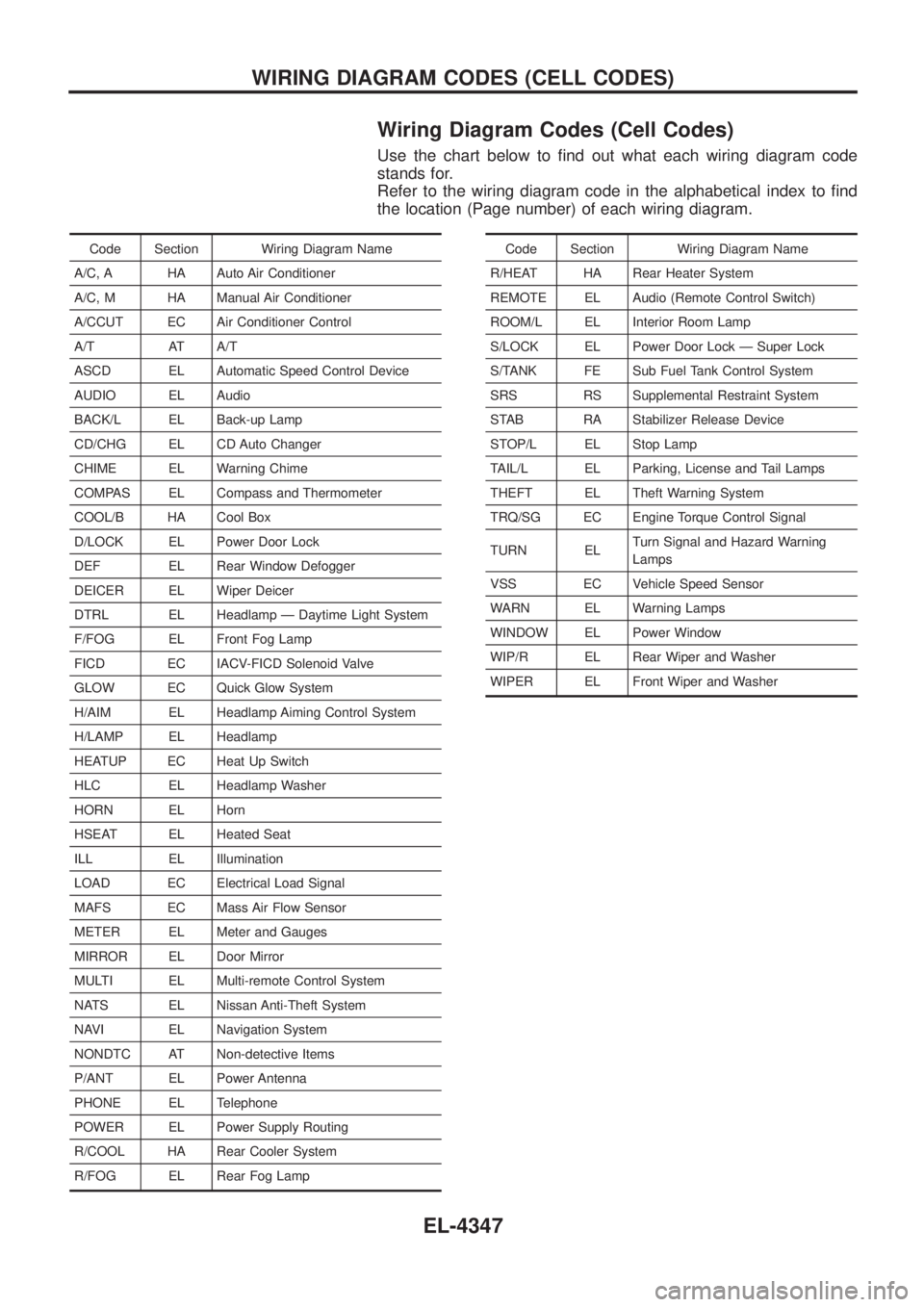
Wiring Diagram Codes (Cell Codes)
Use the chart below to ®nd out what each wiring diagram code
stands for.
Refer to the wiring diagram code in the alphabetical index to ®nd
the location (Page number) of each wiring diagram.
Code Section Wiring Diagram Name
A/C, A HA Auto Air Conditioner
A/C, M HA Manual Air Conditioner
A/CCUT EC Air Conditioner Control
A/T AT A/T
ASCD EL Automatic Speed Control Device
AUDIO EL Audio
BACK/L EL Back-up Lamp
CD/CHG EL CD Auto Changer
CHIME EL Warning Chime
COMPAS EL Compass and Thermometer
COOL/B HA Cool Box
D/LOCK EL Power Door Lock
DEF EL Rear Window Defogger
DEICER EL Wiper Deicer
DTRL EL Headlamp Ð Daytime Light System
F/FOG EL Front Fog Lamp
FICD EC IACV-FICD Solenoid Valve
GLOW EC Quick Glow System
H/AIM EL Headlamp Aiming Control System
H/LAMP EL Headlamp
HEATUP EC Heat Up Switch
HLC EL Headlamp Washer
HORN EL Horn
HSEAT EL Heated Seat
ILL EL Illumination
LOAD EC Electrical Load Signal
MAFS EC Mass Air Flow Sensor
METER EL Meter and Gauges
MIRROR EL Door Mirror
MULTI EL Multi-remote Control System
NATS EL Nissan Anti-Theft System
NAVI EL Navigation System
NONDTC AT Non-detective Items
P/ANT EL Power Antenna
PHONE EL Telephone
POWER EL Power Supply Routing
R/COOL HA Rear Cooler System
R/FOG EL Rear Fog LampCode Section Wiring Diagram Name
R/HEAT HA Rear Heater System
REMOTE EL Audio (Remote Control Switch)
ROOM/L EL Interior Room Lamp
S/LOCK EL Power Door Lock Ð Super Lock
S/TANK FE Sub Fuel Tank Control System
SRS RS Supplemental Restraint System
STAB RA Stabilizer Release Device
STOP/L EL Stop Lamp
TAIL/L EL Parking, License and Tail Lamps
THEFT EL Theft Warning System
TRQ/SG EC Engine Torque Control Signal
TURN EL Turn Signal and Hazard Warning
Lamps
VSS EC Vehicle Speed Sensor
WARN EL Warning Lamps
WINDOW EL Power Window
WIP/R EL Rear Wiper and Washer
WIPER EL Front Wiper and Washer
WIRING DIAGRAM CODES (CELL CODES)
EL-4347
Page 451 of 579
Removal
1. Remove the following parts.
+Undercover
+Engine oil (Drain)
+Engine coolant (Drain)
+Engine cover
+Intercooler
+Air inlet pipe
+Air cleaner case
+Throttle body
+Swirl and intake air control valve control solenoid valve and
bracket
+Vacuum tank
+Glow plate
+Rocker cover
+Spill tube
+Radiator shrouds (Rear and Lower)
+Cooling fan
+Radiator hose (Upper and Lower)
+Auxiliary belt and auto tensioner.
2. Remove the alternator.
3. Remove the A/C compressor and bracket with piping con-
nected. Move and support it at the LH side of engine bay with
a rope to avoid putting load on piping.
Refer to HA section in NISSAN Service Manual (Publication No.
SM9E-Y61CG2 or SM9E-Y61CG3).
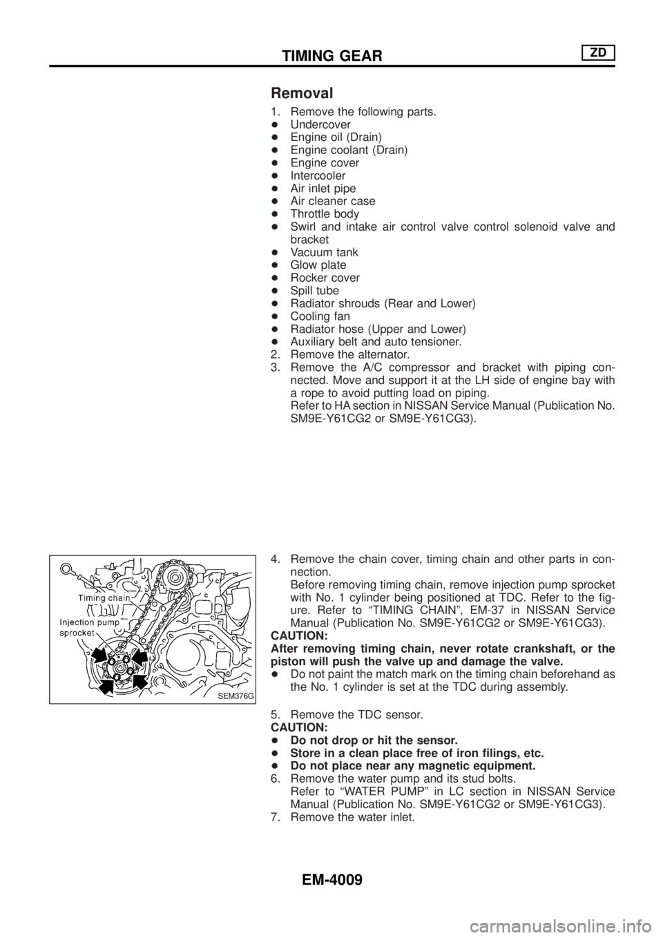
4. Remove the chain cover, timing chain and other parts in con-
nection.
Before removing timing chain, remove injection pump sprocket
with No. 1 cylinder being positioned at TDC. Refer to the ®g-
ure. Refer to ªTIMING CHAINº, EM-37 in NISSAN Service
Manual (Publication No. SM9E-Y61CG2 or SM9E-Y61CG3).
CAUTION:
After removing timing chain, never rotate crankshaft, or the
piston will push the valve up and damage the valve.
+Do not paint the match mark on the timing chain beforehand as
the No. 1 cylinder is set at the TDC during assembly.
5. Remove the TDC sensor.
CAUTION:
+Do not drop or hit the sensor.
+Store in a clean place free of iron ®lings, etc.
+Do not place near any magnetic equipment.
6. Remove the water pump and its stud bolts.
Refer to ªWATER PUMPº in LC section in NISSAN Service
Manual (Publication No. SM9E-Y61CG2 or SM9E-Y61CG3).
7. Remove the water inlet.
SEM376G
TIMING GEARZD
EM-4009
Page 456 of 579
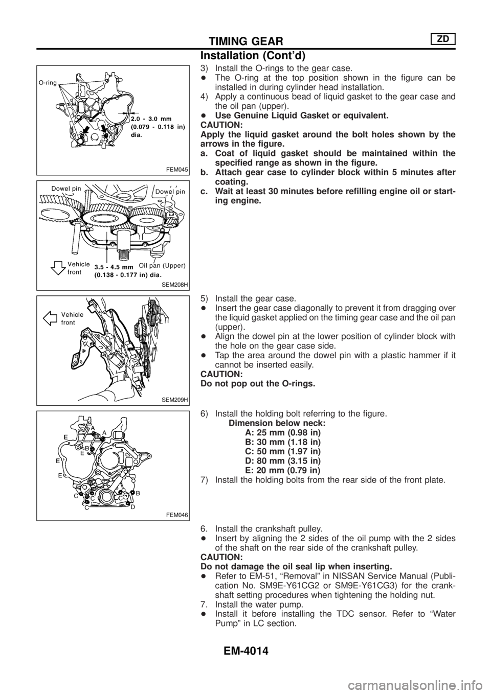
3) Install the O-rings to the gear case.
+The O-ring at the top position shown in the ®gure can be
installed in during cylinder head installation.
4) Apply a continuous bead of liquid gasket to the gear case and
the oil pan (upper).
+Use Genuine Liquid Gasket or equivalent.
CAUTION:
Apply the liquid gasket around the bolt holes shown by the
arrows in the ®gure.
a. Coat of liquid gasket should be maintained within the
speci®ed range as shown in the ®gure.
b. Attach gear case to cylinder block within 5 minutes after
coating.
c. Wait at least 30 minutes before re®lling engine oil or start-
ing engine.
5) Install the gear case.
+Insert the gear case diagonally to prevent it from dragging over
the liquid gasket applied on the timing gear case and the oil pan
(upper).
+Align the dowel pin at the lower position of cylinder block with
the hole on the gear case side.
+Tap the area around the dowel pin with a plastic hammer if it
cannot be inserted easily.
CAUTION:
Do not pop out the O-rings.
6) Install the holding bolt referring to the ®gure.
Dimension below neck:
A: 25 mm (0.98 in)
B: 30 mm (1.18 in)
C: 50 mm (1.97 in)
D: 80 mm (3.15 in)
E: 20 mm (0.79 in)
7) Install the holding bolts from the rear side of the front plate.
6. Install the crankshaft pulley.
+Insert by aligning the 2 sides of the oil pump with the 2 sides
of the shaft on the rear side of the crankshaft pulley.
CAUTION:
Do not damage the oil seal lip when inserting.
+Refer to EM-51, ªRemovalº in NISSAN Service Manual (Publi-
cation No. SM9E-Y61CG2 or SM9E-Y61CG3) for the crank-
shaft setting procedures when tightening the holding nut.
7. Install the water pump.
+Install it before installing the TDC sensor. Refer to ªWater
Pumpº in LC section.
FEM045
SEM208H
SEM209H
FEM046
TIMING GEARZD
Installation (Cont'd)
EM-4014
Page 457 of 579
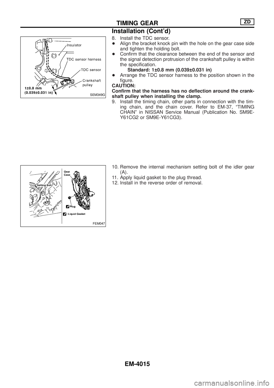
8. Install the TDC sensor.
+Align the bracket knock pin with the hole on the gear case side
and tighten the holding bolt.
+Con®rm that the clearance between the end of the sensor and
the signal detection protrusion of the crankshaft pulley is within
the speci®cation.
Standard: 1 0.8 mm (0.039 0.031 in)
+Arrange the TDC sensor harness to the position shown in the
®gure.
CAUTION:
Con®rm that the harness has no de¯ection around the crank-
shaft pulley when installing the clamp.
9. Install the timing chain, other parts in connection with the tim-
ing chain, and the chain cover. Refer to EM-37, ªTIMING
CHAINº in NISSAN Service Manual (Publication No. SM9E-
Y61CG2 or SM9E-Y61CG3).
10. Remove the internal mechanism setting bolt of the idler gear
(A).
11. Apply liquid gasket to the plug thread.
12. Install in the reverse order of removal.
SEM349G
FEM047
TIMING GEARZD
Installation (Cont'd)
EM-4015
Page 481 of 579
Features (TB48 Engine Models)
CAN COMMUNICATION SYSTEM DESCRIPTION
CAN (Controller Area Network) is a serial communication line for real time application. It is an on-vehicle mul-
tiplex communication line with high data communication speed and excellent error detection ability. Many
electronic control units are equipped onto a vehicle, and each control unit shares information and links with
other control units during operation (not independent). In CAN communication, control units are connected with
2 communication lines (CAN H line, CAN L line) allowing a high rate of information transmission with less wir-
ing. Each control unit transmits/receives data but selectively reads required data only.
SYSTEM CONSTRUCTION
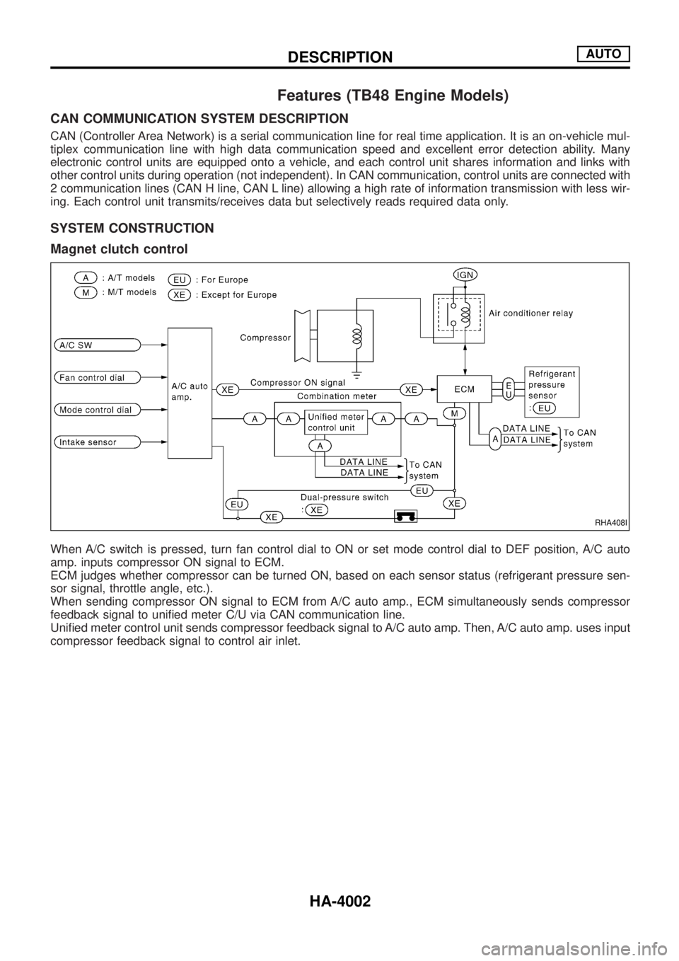
Magnet clutch control
When A/C switch is pressed, turn fan control dial to ON or set mode control dial to DEF position, A/C auto
amp. inputs compressor ON signal to ECM.
ECM judges whether compressor can be turned ON, based on each sensor status (refrigerant pressure sen-
sor signal, throttle angle, etc.).
When sending compressor ON signal to ECM from A/C auto amp., ECM simultaneously sends compressor
feedback signal to uni®ed meter C/U via CAN communication line.
Uni®ed meter control unit sends compressor feedback signal to A/C auto amp. Then, A/C auto amp. uses input
compressor feedback signal to control air inlet.
RHA408I
DESCRIPTIONAUTO
HA-4002
Page 504 of 579
Self-diagnosis
INTRODUCTION AND GENERAL DESCRIPTION
The self-diagnostic system diagnoses sensors, door motors, blower motor, etc. by system line.
Self-diagnosis is step-1 to 7. There are two ways of changing method during self-diagnosis.
+Switching to self-diagnosis step-1 to 4.
Shifting from usual control to the self-diagnostic system is accomplished by starting the engine (turning
the ignition switch from OFF to ON) and pressing A/C switch for at least 5 seconds. The A/C switch must
be pressed within 10 seconds after starting the engine (ignition switch is turned ON). This system will be
canceled by either pressing intake switch or turning the ignition switch OFF. Shifting from one step to
another is accomplished be means of turning fan control dial, as required.
+Switching to self-diagnosis step-5 to 7 (Auxiliary mechanism).
Shifting from usual control to the self-diagnostic system is accomplished by starting the engine (turning
the ignition switch from OFF to ON) and pressing intake switch for at least 5 seconds. The intake switch
must be pressed within 10 seconds after starting the engine (ignition switch is turned ON). This system
will be canceled by either pressing A/C switch or turning the ignition switch OFF. Shifting from one step
to another is accomplished by means of turning fan control dial, as required.
TROUBLE DIAGNOSESAUTO
HA-4025
Page 507 of 579
jA
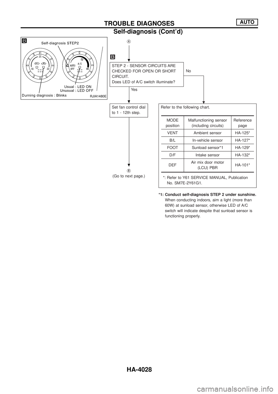
STEP 2 - SENSOR CIRCUITS ARE
CHECKED FOR OPEN OR SHORT
CIRCUIT.
Does LED of A/C switch illuminate?
Ye sNo
.
Set fan control dial
to 1 - 12th step.Refer to the following chart.
*: Refer to Y61 SERVICE MANUAL, Publication
No. SM7E-2Y61G1.
*1: Conduct self-diagnosis STEP 2 under sunshine.
When conducting indoors, aim a light (more than
60W) at sunload sensor, otherwise LED of A/C
switch will indicate despite that sunload sensor is
functioning properly. j
B
(Go to next page.)
MODE
positionMalfunctioning sensor
(including circuits)Reference
page
VENT Ambient sensor HA-125*
B/L In-vehicle sensor HA-127*
FOOT Sunload sensor*1 HA-129*
D/F Intake sensor HA-132*
DEFAir mix door motor
(LCU) PBRHA-101*
RJIA1480E
.
.
.
TROUBLE DIAGNOSESAUTO
Self-diagnosis (Cont'd)
HA-4028