Page 980 of 3870
1. Set the auto-cruise speed control.
2. When any of the following operations are performed while at constant speed
during auto-cruise control, check if normal driving is resumed and deceleration
occurs.
1. The auto-cruise control switch is pulled in the direction of arrow.
2. The brake pedal is depressed.
3. The selector lever is moved to the "N" range.
3. At a vehicle speed of 40 km/h (25 mph) or higher, check if when the
"ACC/RES" switch is switched ON, the vehicle speed returns to the speed
before auto-cruise control driving was cancelled, and constant speed driving
occurs.
Fig. 109: Resuming Set Speed
Courtesy of MITSUBISHI MOTOR SALES OF AMERICA.
4. When the "CRUISE" (MAIN) switch is turned to the "OFF" while driving at
constant speed, check if normal driving is resumed and deceleration occurs.
AUTO-CRUISE CONTROL SYSTEM COMPONENT CHECK STOPLIGHT SWITCH
2004 Mitsubishi Endeavor LS
2004 BODY & ACCESSORIES Auto, Cruise Control System - Endeavor
Page 1093 of 3870
2004 MITSUBISH
I
Endeavor
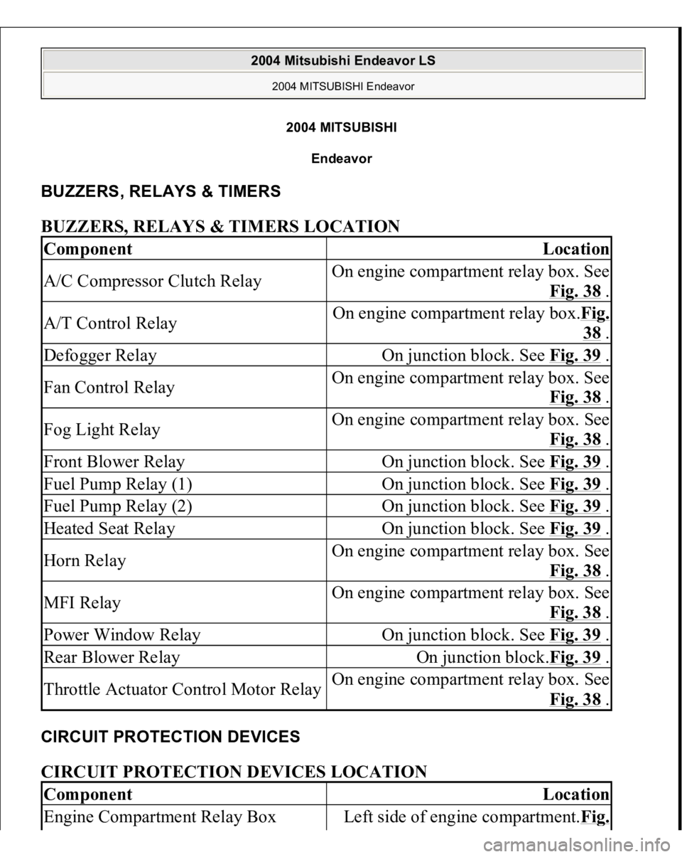
BUZZERS, RELAYS & TIMERS BUZZERS, RELAYS & TIMERS LOCATION CIRCUIT PROTECTION DEVICES CIRCUIT PROTECTION DEVICES LOCATION Component
Location
A/C Compressor Clutch Relay
On engine compartment relay box. See
Fig. 38
.
A/T Control Relay
On engine compartment relay box.Fig.
38 .
Defogger Relay
On junction block. See Fig. 39
.
Fan Control Relay
On engine compartment relay box. See
Fig. 38
.
Fog Light Relay
On engine compartment relay box. See
Fig. 38
.
Front Blower Relay
On junction block. See Fig. 39
.
Fuel Pump Relay (1)
On junction block. See Fig. 39
.
Fuel Pump Relay (2)
On junction block. See Fig. 39
.
Heated Seat Relay
On junction block. See Fig. 39
.
Horn Relay
On engine compartment relay box. See
Fig. 38
.
MFI Relay
On engine compartment relay box. See
Fig. 38
.
Power Window Relay
On junction block. See Fig. 39
.
Rear Blower Relay
On junction block.Fig. 39
.
Throttle Actuator Control Motor Relay
On engine compartment relay box. See
Fig. 38
.
Component
Location
Engine Compartment Relay Box
Left side of engine compartment.Fi
g.
2004 Mitsubishi Endeavor LS
2004 MITSUBISHI Endeavor
2004 Mitsubishi Endeavor LS
2004 MITSUBISHI Endeavor
Page 1098 of 3870
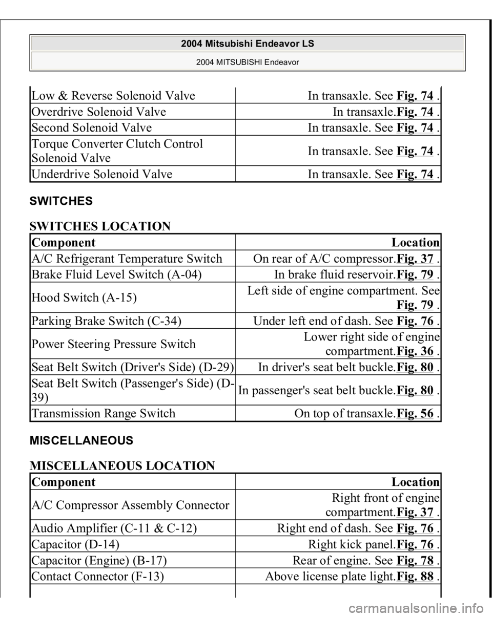
SWITCHES SWITCHES LOCATION MISCELLANEOUS MISCELLANEOUS LOCATION Low & Reverse Solenoid Valve
In transaxle. See Fig. 74
.
Overdrive Solenoid Valve
In transaxle.Fig. 74
.
Second Solenoid Valve
In transaxle. See Fig. 74
.
Torque Converter Clutch Control
Solenoid Valve
In transaxle. See Fig. 74
.
Underdrive Solenoid Valve
In transaxle. See Fig. 74
.
Component
Location
A/C Refrigerant Temperature Switch
On rear of A/C compressor.Fig. 37
.
Brake Fluid Level Switch (A-04)
In brake fluid reservoir.Fig. 79
.
Hood Switch (A-15)
Left side of engine compartment. See
Fig. 79
.
Parking Brake Switch (C-34)
Under left end of dash. See Fig. 76
.
Power Steering Pressure Switch
Lower right side of engine
compartment.Fig. 36
.
Seat Belt Switch (Driver's Side) (D-29)
In driver's seat belt buckle.Fig. 80
.
Seat Belt Switch (Passenger's Side) (D-
39)
In passenger's seat belt buckle.Fig. 80
.
Transmission Range Switch
On top of transaxle.Fig. 56
.
Component
Location
A/C Compressor Assembly Connector
Right front of engine
compartment.Fig. 37
.
Audio Amplifier (C-11 & C-12)
Right end of dash. See Fig. 76
.
Capacitor (D-14)
Right kick panel.Fig. 76
.
Capacitor (Engine) (B-17)
Rear of engine. See Fig. 78
.
Contact Connector (F-13)
Above license plate light.Fig. 88
.
2004 Mitsubishi Endeavor LS
2004 MITSUBISHI Endeavor
Page 1099 of 3870
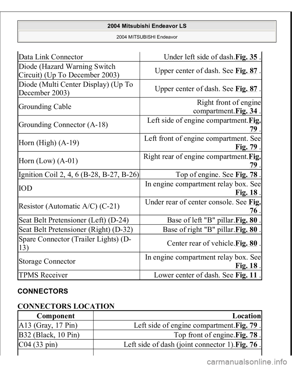
CONNECTORS CONNECTORS LOCATION Data Link Connector
Under left side of dash.Fig. 35
.
Diode (Hazard Warning Switch
Circuit) (Up To December 2003)
Upper center of dash. See Fig. 87
.
Diode (Multi Center Display) (Up To
December 2003)
Upper center of dash. See Fig. 87
.
Grounding Cable
Right front of engine
compartment.Fig. 34
.
Grounding Connector (A-18)
Left side of engine compartment.Fig.
79 .
Horn (High) (A-19)
Left front of engine compartment. See
Fig. 79
.
Horn (Low) (A-01)
Right rear of engine compartment.Fi
g.
79 .
Ignition Coil 2, 4, 6 (B-28, B-27, B-26)
Top of engine. See Fig. 78
.
IOD
In engine compartment relay box. See
Fig. 18
.
Resistor (Automatic A/C) (C-21)
Under rear of center console. See Fi
g.
76 .
Seat Belt Pretensioner (Left) (D-24)
Base of left "B" pillar.Fig. 80
.
Seat Belt Pretensioner (Right) (D-32)
Base of right "B" pillar.Fig. 80
.
Spare Connector (Trailer Lights) (D-
13)
Center rear of vehicle.Fig. 80
.
Storage Connector
In engine compartment relay box. See
Fig. 18
.
TPMS Receiver
Lower center of dash. See Fig. 11
.
Component
Location
A13 (Gray, 17 Pin)
Left side of engine compartment.Fig. 79
.
B32 (Black, 10 Pin)
Top front of engine.Fig. 78
.
C04 (33 pin)
Left side of dash (joint connector 1).Fig. 76
.
2004 Mitsubishi Endeavor LS
2004 MITSUBISHI Endeavor
Page 1269 of 3870
2004 STARTING & CHARGING SYSTEMS
Generators & Regulators - Endeavor
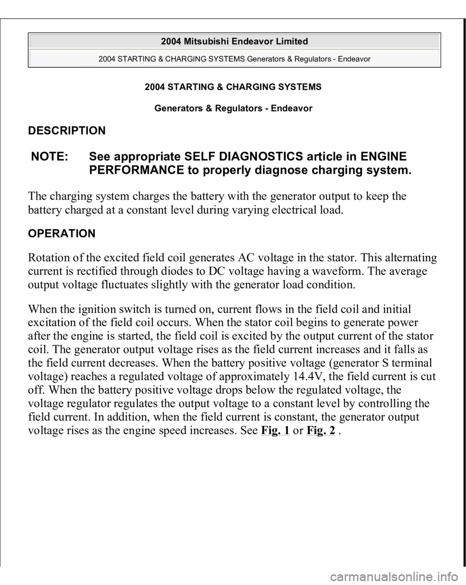
DESCRIPTION The charging system charges the battery with the generator output to keep the
battery charged at a constant level during varying electrical load. OPERATION Rotation of the excited field coil generates AC voltage in the stator. This alternating
current is rectified through diodes to DC voltage having a waveform. The average
output voltage fluctuates slightly with the generator load condition.
When the ignition switch is turned on, current flows in the field coil and initial
excitation of the field coil occurs. When the stator coil begins to generate power
after the engine is started, the field coil is excited by the output current of the stator
coil. The generator output voltage rises as the field current increases and it falls as
the field current decreases. When the battery positive voltage (generator S terminal
voltage) reaches a regulated voltage of approximately 14.4V, the field current is cut
off. When the battery positive voltage drops below the regulated voltage, the
voltage regulator regulates the output voltage to a constant level by controlling the
field current. In addition, when the field current is constant, the generator output
volta
ge rises as the en
gine s
peed increases. See Fig. 1
or Fig. 2
.
NOTE: See appropriate SELF DIAGNOSTICS article in ENGINE
PERFORMANCE to properly diagnose charging system.
2004 Mitsubishi Endeavor Limited
2004 STARTING & CHARGING SYSTEMS Generators & Regulators - Endeavor
2004 Mitsubishi Endeavor Limited
2004 STARTING & CHARGING SYSTEMS Generators & Regulators - Endeavor
Page 1271 of 3870
For belt tension, see ADJUSTMENTS
.
TROUBLE SHOOTING 1. Is battery in good condition?
If Yes, then go to next step. If No, then charge or replace battery.
2. Is generator drive belt in good condition? If Yes, then go to next step. If No, then adjust belt tension or replace belt.
3. Does the generator malfunction light come on when the ignition switch is
turned on? If Yes, then go to next step. If No:
Check the ignition switch.
Check for burnt-out generator malfunction light.
Check the generator.
Check the generator malfunction light-related circuits.
4. Does the generator malfunction light go out after starting the engine? If Yes, then go to next step. If No, check the generator.
5. Is an oscilloscope available? If Yes, then go to next step. If No, then go to step 7 .
6. Does the oscilloscope show a normal wave pattern? If Yes, then go to next step. If No, then check the generator.
7. Turn the engine on and idle at 2500 RPM. Turn the headlights on with the
High Beams on. Be sure that there is voltage between generator terminal B and
the positive battery terminal of 0.5V or less. Check that the voltage between
the negative batter
y terminal and
generator bod
y is 0.5V or less. Are the
2004 Mitsubishi Endeavor Limited
2004 STARTING & CHARGING SYSTEMS Generators & Regulators - Endeavor
Page 1274 of 3870
4. Connect a clamp-type DC test ammeter with a range of 0-150A to the
generator B terminal output wire.
5. Connect a digital-type voltmeter between the generator B terminal and the
positive battery terminal. (Connect the positive lead of the voltmeter to the B
terminal, and then connect the negative lead of the voltmeter to the positive
battery cable.)
6. Reconnect the negative battery cable.
7. Connect an engine tachometer or scan tool MB991958.
8. Leave the hood open.
9. Start the engine.
10. With the engine running at 2500 RPM, turn the headlights and other lights on
and off to adjust the generator load so that the value displayed on the ammeter
is slightly above 30A. Read the voltmeter. Voltage reading at or below limit
value means voltage drop between generator and batter is OK. There should be
a maximum voltage of 0.3V.
11. If the value displayed on the voltmeter is above the limit value, there is
probably a malfunction in the generator output wire. Check the wiring between
the
generator B terminal and the
positive batter
y terminal
(includin
g fusible
NOTE: The way of disconnecting the generator output wire and
of connecting the ammeter is possibly not found the
problem that the output current is dropping due to the
insufficient connection between terminal B and the
output wire.
NOTE: When the generator output is high and the value
displayed on the ammeter does not decrease to 30A,
set the value to 40A. Read the value displayed on the
voltmeter at this time. In the case the limit value
becomes maximum 0.4V. Adjust the engine speed by
gradually decreasing it until the value displayed on the
ammeter is 30A. Take a reading of the value displayed
on the voltmeter at this time
2004 Mitsubishi Endeavor Limited
2004 STARTING & CHARGING SYSTEMS Generators & Regulators - Endeavor
Page 1275 of 3870
link). If a terminal is not sufficiently tight or if the harness has become
discolored due to overheating, repair and then test again.
12. After the test, run the engine at idle.
13. Turn off all lights and turn the ignition switch to the LOCK (OFF) position.
14. Disconnect the negative battery cable.
15. Disconnect the ammeter and voltmeter.
16. Connect the negative battery cable.
17. Run engine for 10 minutes at an idle.
OUTPUT CURRENT TEST Required special tool: MB991958: Scan Tool MUT-III Sub Assembly, MB991824:
V.C.I., MB991827 MUT-III USB Cable, MB5991910: MUT-III Main Harness A.
This test determines whether the generator outputs normal current. For best results,
use a char
ging system tester. If not available, follow the ste
ps below. See Fig. 4
.
2004 Mitsubishi Endeavor Limited
2004 STARTING & CHARGING SYSTEMS Generators & Regulators - Endeavor