Page 271 of 3870
2. With the ignition switch turned to the "ON" position, read the voltage between
terminals number 2 and number 3.
Standard Value: 2.4 - 2.6 V
3. With special tool MB991348 connected, rotate so that the arrow points straight
down. Read output voltage between terminals number 2 and number 3.
Standard Value: 3.4 - 3.6 V
4. If the voltage deviates from the standard value, check the power supply wire
and ground wire. If no problems are found, replace the G-sensor. SPECIFICATIONS FASTENER TIGHTENING SPECIFICATION FASTENER TIGHTENING SPECIFICATION GENERAL SPECIFICATIONS Fig. 166: General Specifications
Courtesy of MITSUBISHI MOTOR SALES OF AMERICA.
SERVICE SPECIFICATION ITEM
SPECIFICATION
Brake tube flare nut
15 +/- 2 N.m (12 +/- 1 ft-lb)
2004 Mitsubishi Endeavor LS
2004 BRAKES Anti-Lock Braking System (ABS) - Endeavor
Page 1095 of 3870

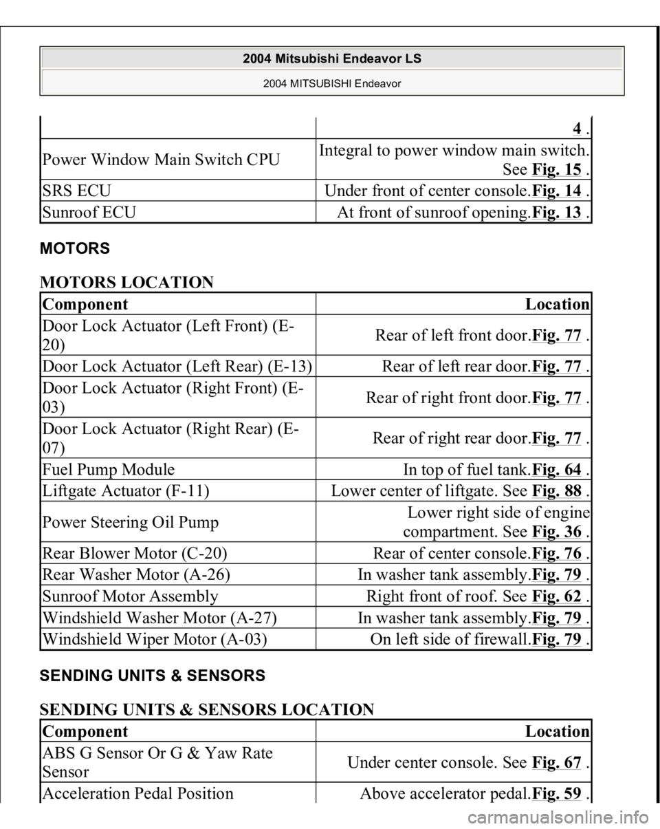
MOTORS MOTORS LOCATION SENDING UNITS & SENSORS SENDING UNITS & SENSORS LOCATION
4 .
Power Window Main Switch CPU
Integral to power window main switch.
See Fig. 15
.
SRS ECU
Under front of center console.Fig. 14
.
Sunroof ECU
At front of sunroof opening.Fig. 13
.
Component
Location
Door Lock Actuator (Left Front) (E-
20)
Rear of left front door.Fig. 77
.
Door Lock Actuator (Left Rear) (E-13)
Rear of left rear door.Fig. 77
.
Door Lock Actuator (Right Front) (E-
03)
Rear of right front door.Fig. 77
.
Door Lock Actuator (Right Rear) (E-
07)
Rear of right rear door.Fig. 77
.
Fuel Pump Module
In top of fuel tank.Fig. 64
.
Liftgate Actuator (F-11)
Lower center of liftgate. See Fig. 88
.
Power Steering Oil Pump
Lower right side of engine
compartment. See Fig. 36
.
Rear Blower Motor (C-20)
Rear of center console.Fig. 76
.
Rear Washer Motor (A-26)
In washer tank assembly.Fig. 79
.
Sunroof Motor Assembly
Right front of roof. See Fig. 62
.
Windshield Washer Motor (A-27)
In washer tank assembly.Fig. 79
.
Windshield Wiper Motor (A-03)
On left side of firewall.Fig. 79
.
Component
Location
ABS G Sensor Or G & Yaw Rate
Sensor
Under center console. See Fig. 67
.
Acceleration Pedal Position
Above accelerator pedal.Fig. 59
.
2004 Mitsubishi Endeavor LS
2004 MITSUBISHI Endeavor
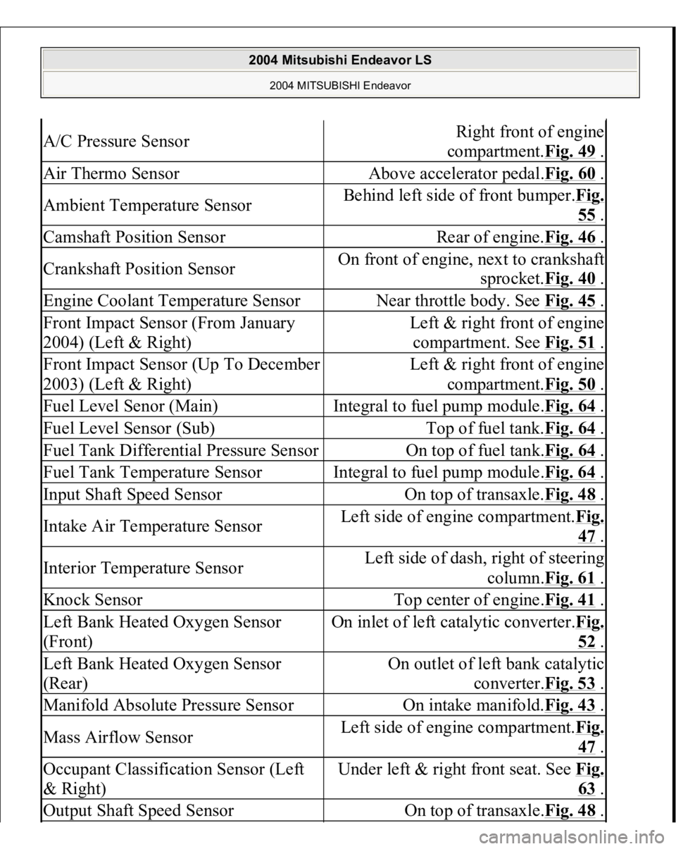
Page 1096 of 3870

A/C Pressure Sensor
Right front of engine
compartment.Fig. 49
.
Air Thermo Sensor
Above accelerator pedal.Fig. 60
.
Ambient Temperature Sensor
Behind left side of front bumper.Fig.
55 .
Camshaft Position Sensor
Rear of engine.Fig. 46
.
Crankshaft Position Sensor
On front of engine, next to crankshaft
sprocket.Fig. 40
.
Engine Coolant Temperature Sensor
Near throttle body. See Fig. 45
.
Front Impact Sensor (From January
2004) (Left & Right)
Left & right front of engine
compartment. See Fig. 51
.
Front Impact Sensor (Up To December
2003) (Left & Right)
Left & right front of engine
compartment.Fig. 50
.
Fuel Level Senor (Main)
Integral to fuel pump module.Fig. 64
.
Fuel Level Sensor (Sub)
Top of fuel tank.Fig. 64
.
Fuel Tank Differential Pressure Sensor
On top of fuel tank.Fig. 64
.
Fuel Tank Temperature Sensor
Integral to fuel pump module.Fig. 64
.
Input Shaft Speed Sensor
On top of transaxle.Fig. 48
.
Intake Air Temperature Sensor
Left side of engine compartment.Fi
g.
47 .
Interior Temperature Sensor
Left side of dash, right of steering
column.Fig. 61
.
Knock Sensor
Top center of engine.Fig. 41
.
Left Bank Heated Oxygen Sensor
(Front)
On inlet of left catalytic converter.Fi
g.
52 .
Left Bank Heated Oxygen Sensor
(Rear)
On outlet of left bank catalytic
converter.Fig. 53
.
Manifold Absolute Pressure Sensor
On intake manifold.Fig. 43
.
Mass Airflow Sensor
Left side of engine compartment.Fi
g.
47 .
Occupant Classification Sensor (Left
& Right)
Under left & right front seat. See Fi
g.
63 .
Output Shaft Speed Sensor
On top of transaxle.Fig. 48
.
2004 Mitsubishi Endeavor LS
2004 MITSUBISHI Endeavor
Page 1097 of 3870

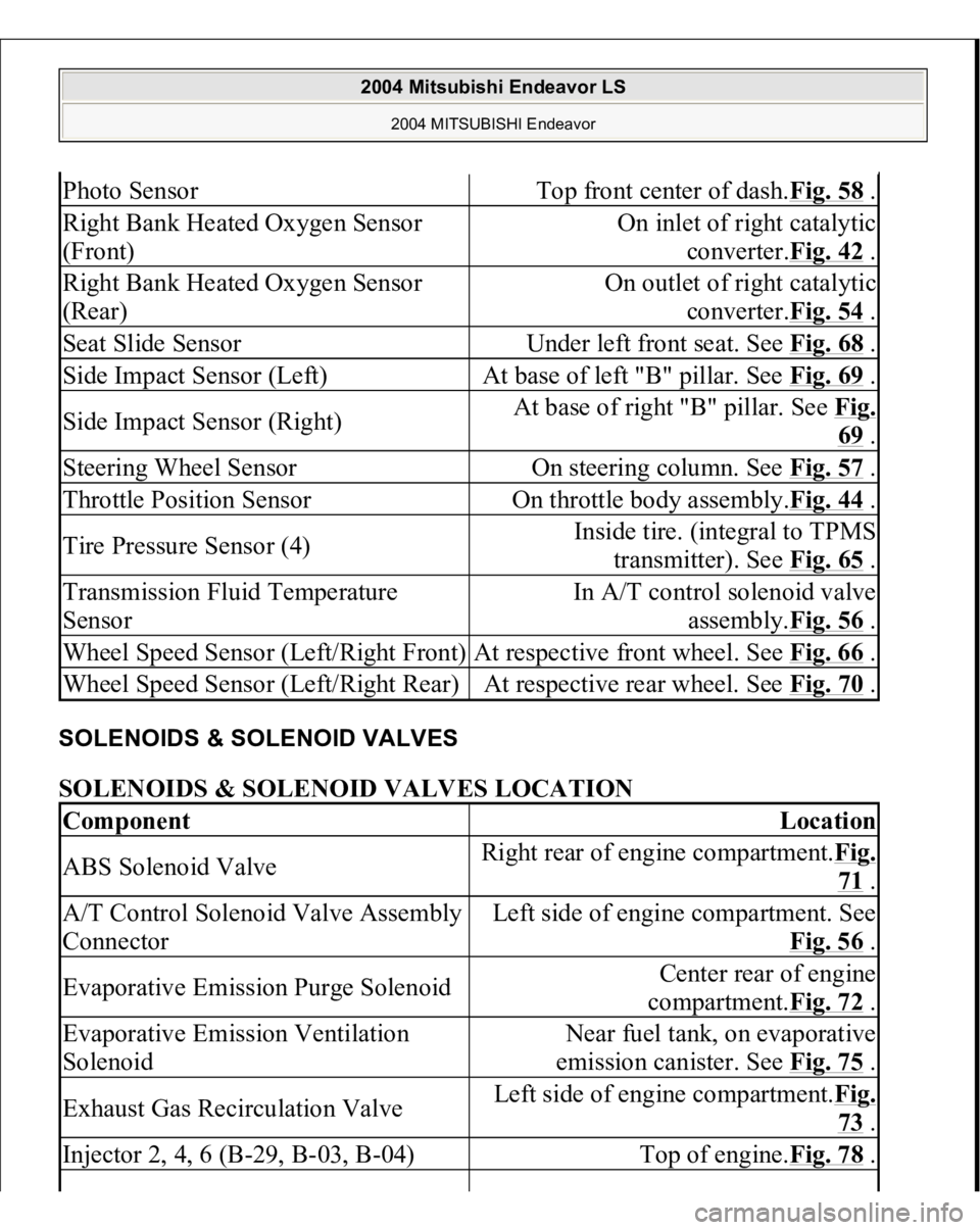
SOLENOIDS & SOLENOID VALVES SOLENOIDS & SOLENOID VALVES LOCATION Photo Sensor
Top front center of dash.Fig. 58
.
Right Bank Heated Oxygen Sensor
(Front)
On inlet of right catalytic
converter.Fig. 42
.
Right Bank Heated Oxygen Sensor
(Rear)
On outlet of right catalytic
converter.Fig. 54
.
Seat Slide Sensor
Under left front seat. See Fig. 68
.
Side Impact Sensor (Left)
At base of left "B" pillar. See Fig. 69
.
Side Impact Sensor (Right)
At base of right "B" pillar. See Fig.
69 .
Steering Wheel Sensor
On steering column. See Fig. 57
.
Throttle Position Sensor
On throttle body assembly.Fig. 44
.
Tire Pressure Sensor (4)
Inside tire. (integral to TPMS
transmitter). See Fig. 65
.
Transmission Fluid Temperature
Sensor
In A/T control solenoid valve
assembly.Fig. 56
.
Wheel Speed Sensor (Left/Right Front)
At respective front wheel. See Fig. 66
.
Wheel Speed Sensor (Left/Right Rear)
At respective rear wheel. See Fig. 70
.
Component
Location
ABS Solenoid Valve
Right rear of engine compartment.Fig.
71 .
A/T Control Solenoid Valve Assembly
Connector
Left side of engine compartment. See
Fig. 56
.
Evaporative Emission Purge Solenoid
Center rear of engine
compartment.Fig. 72
.
Evaporative Emission Ventilation
Solenoid
Near fuel tank, on evaporative
emission canister. See Fig. 75
.
Exhaust Gas Recirculation Valve
Left side of engine compartment.Fig.
73 .
Injector 2, 4, 6 (B-29, B-03, B-04)
Top of engine.Fig. 78
.
2004 Mitsubishi Endeavor LS
2004 MITSUBISHI Endeavor
Page 1851 of 3870
2004 DRIVELINE/AXLES
Front Axle Hub & Axle Shafts - Endeavor
FRONT AXLE HUB ASSEMBLY REMOVAL AND INSTALLATION
CAUTION:
For vehicles with ABS, do not strike the ABS
rotors installed to the BJ outer race of drive shaft
against other parts when removing or installing
the drive shaft. Otherwise the ABS rotors will be
damaged. For vehicles with ABS, be careful not to strike the
pole piece at the tip of the front ABS sensor with
tools during servicing work.
2004 Mitsubishi Endeavor LS
2004 DRIVELINE/AXLES Front Axle Hub & Axle Shafts - Endeavor
2004 Mitsubishi Endeavor LS
2004 DRIVELINE/AXLES Front Axle Hub & Axle Shafts - Endeavor
Page 1863 of 3870
Fig. 11: Measuring Wheel Bearing Axial Play
Courtesy of MITSUBISHI MOTOR SALES OF AMERICA.
DRIVE SHAFT ASSEMBLY REMOVAL AND INSTALLATION
CAUTION:
For vehicles with ABS, do not strike the ABS
rotors installed to the BJ outer race of drive shaft
against other parts when removing or installing
the drive shaft. Otherwise the ABS rotors will be
damaged. For vehicles with ABS, be careful not to strike the
pole piece at the tip of the front ABS sensor with
tools during servicing work.
2004 Mitsubishi Endeavor LS
2004 DRIVELINE/AXLES Front Axle Hub & Axle Shafts - Endeavor
Page 2952 of 3870
REAR AXLE HUB ASSEMBL
Y
REMOVAL AND INSTALLATION Fig. 17: Removing/Installing Rear Axle Hub Assembly Components
Courtesy of MITSUBISHI MOTOR SALES OF AMERICA.
Required Special Tool:
MB990767: End Yoke Holder
MB990241: Axle Shaft Puller
MB991354: Puller Bod
y
CAUTION:
For vehicles with ABS, be careful not to strike the
pole piece at the tip of the rear ABS sensor with
tools during servicing work. The rear hub assembly should not be dismantled.
2004 Mitsubishi Endeavor LS
2004 SUSPENSION Rear Axle < AWD > - Endeavor
Page 3074 of 3870
2. If the dust cover is cracked or damaged, replace the stabilizer bar link
assembly. REAR SUSPENSION CROSSMEMBER REMOVAL AND INSTALLATION < FWD>
NOTE: Cracks or damage of the dust cover may cause damage
to the ball joint.
CAUTION: For vehicles with ABS, be careful when handling the
pole piece at the tip of the ABS sensor so as not to
damage it by striking against other parts.
2004 Mitsubishi Endeavor LS 2004 SUSPENSION Rear - Endeavor