Page 2738 of 3870

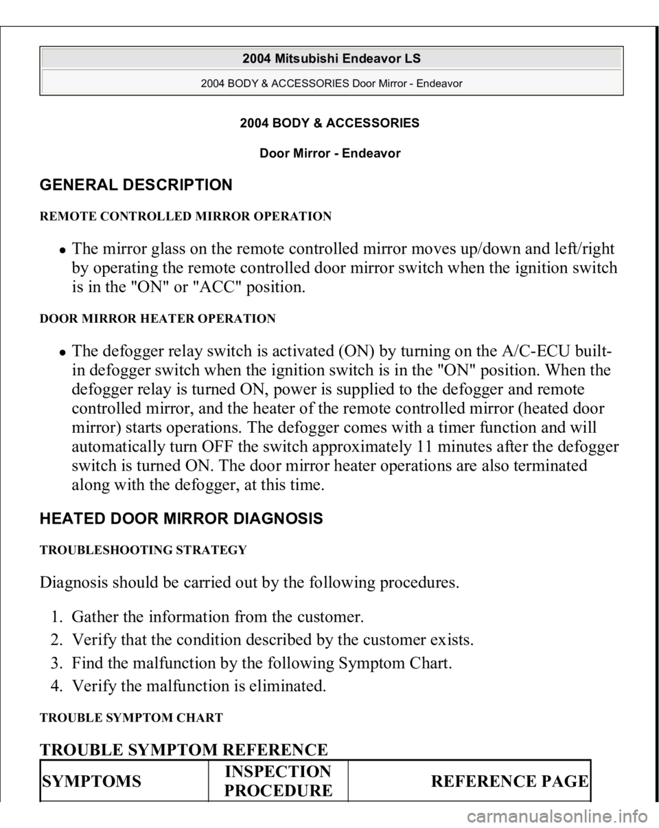
2004 BODY & ACCESSORIES
Door Mirror - Endeavor
GENERAL DESCRIPTION REMOTE CONTROLLED MIRROR OPERATION
The mirror glass on the remote controlled mirror moves up/down and left/right
by operating the remote controlled door mirror switch when the ignition switch
is in the "ON" or "ACC" position.
DOOR MIRROR HEATER OPERATION
The defogger relay switch is activated (ON) by turning on the A/C-ECU built-
in defogger switch when the ignition switch is in the "ON" position. When the
defogger relay is turned ON, power is supplied to the defogger and remote
controlled mirror, and the heater of the remote controlled mirror (heated door
mirror) starts operations. The defogger comes with a timer function and will
automatically turn OFF the switch approximately 11 minutes after the defogger
switch is turned ON. The door mirror heater operations are also terminated
along with the defogger, at this time.
HEATED DOOR MIRROR DIAGNOSIS TROUBLESHOOTING STRATEGY Diagnosis should be carried out by the following procedures.
1. Gather the information from the customer.
2. Verify that the condition described by the customer exists.
3. Find the malfunction by the following Symptom Chart.
4. Verify the malfunction is eliminated. TROUBLE SYMPTOM CHART TROUBLE SYMPTOM REFERENCE SYMPTOMS
INSPECTION
PROCEDURE
REFERENCE PAGE
2004 Mitsubishi Endeavor LS
2004 BODY & ACCESSORIES Door Mirror - Endeavor
2004 Mitsubishi Endeavor LS
2004 BODY & ACCESSORIES Door Mirror - Endeavor
Page 2797 of 3870
INSTALLATION 1. Tighten the parking brake lever nuts securely.
Fig. 10: Tightening Parking Brake Lever Nuts
Courtesy of MITSUBISHI MOTOR SALES OF AMERICA.
2. Insert the parking brake cable clip securely as illustrated.
3. Check that the pawl has been bent. In addition, check that the bent pawl does
not interfere with the front parking brake cable.
PARKING BRAKE CABLE REMOVAL AND INSTALLATIONNOTE: The bent pawl prevents the front parking brake cable from
falling off the parking brake pedal.
2004 Mitsubishi Endeavor LS 2004 BRAKES Parking Brakes - Endeavor
Page 2799 of 3870
Fig. 12: Removing/Installing Rear Parking Brake Cable
Courtesy of MITSUBISHI MOTOR SALES OF AMERICA.
INSTALLATION SERVICE POINTS >>A<< FRONT PARKING BRAKE CABLE INSTALLATION Install the front parking brake cable securely to the cable support of the parking brake cable bracket.
CAUTION: Be careful not to widen the cable support slit when
installing the front parking brake cable.
2004 Mitsubishi Endeavor LS 2004 BRAKES Parking Brakes - Endeavor
Page 2800 of 3870
Fig. 13: Installing Front Parking Brake Cable
Courtesy of MITSUBISHI MOTOR SALES OF AMERICA.
>>B<< PARKING BRAKE LEVER NUTS/PARKING BRAKE CABLE CLIP INSTALLATION 1. Ti
ghten the
parkin
g brake lever nuts securel
y.
2004 Mitsubishi Endeavor LS 2004 BRAKES Parking Brakes - Endeavor
Page 2801 of 3870
Fig. 14: Tightening Parking Brake Lever Nuts
Courtesy of MITSUBISHI MOTOR SALES OF AMERICA.
2. Insert the parking brake cable clip securely as illustrated.
3. Check that the pawl has been bent. In addition, check that the bent pawl does
not interfere with the front parking brake cable.
PARKING BRAKE LINING AND DRUM REMOVAL AND INSTALLATIONNOTE: The bent pawl prevents the front parking brake cable from
falling off the parking brake pedal.
2004 Mitsubishi Endeavor LS 2004 BRAKES Parking Brakes - Endeavor
Page 2843 of 3870
wheel circumference and check the play.
Standard value (steering wheel play with the engine stopped): 10 mm (0.4
inch) or less
5. If the play exceeds the standard value, remove the steering gear (Refer to
POWER STEERING GEAR BOX AND LINKAGE
.) and check the total
pinion torque (Refer to STEERING GEAR TOTAL PINION TORQUE
CHECK
.).
STEERING ANGLE CHECK 1. Place the front wheel on a turnin
g radius
gauge an
d measure the steerin
g an
gle.
CAUTION: On vehicles with ASC, if the steering angle is
adjusted, always carry out steering wheel sensor
calibration (Refer to STEERING WHEEL SENSOR
CALIBRATION
). This is necessary because the
TCL/ASC-ECU should update the steering neutral
point.
2004 Mitsubishi Endeavor LS
2004 STEERING Power Steering - Endeavor
Page 2855 of 3870
1. Raise and support the front wheels.
2. Disconnect the return hose connection, and then connect a vinyl hose to the
return hose, and drain the fluid into a container.
Fig. 23: Disconnecting Return Hose Connection
Courtesy of MITSUBISHI MOTOR SALES OF AMERICA.
3. Disconnect the ignition coil connectors (Refer to IGNITION COIL
).
4. While operating the starter motor intermittently, turn the steering wheel all the
way to the left and right several times to drain all of the fluid.
5. Connect the return hose securely, and then secure with the clip.
6. Fill the oil reservoir with GENUINE MITSUBISHI POWER STEERING
FLUID up to the lower mark of the reservoir, and then bleed the air.
POWER STEERING SYSTEM AIR BLEEDIN
G
2004 Mitsubishi Endeavor LS
2004 STEERING Power Steering - Endeavor
Page 2870 of 3870

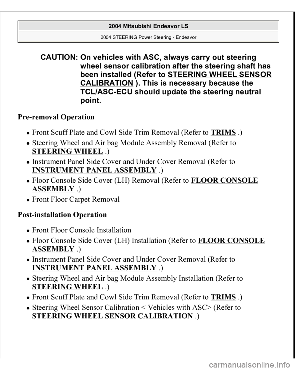
Pre-removal Operation
Front Scuff Plate and Cowl Side Trim Removal (Refer to TRIMS
.)
Steering Wheel and Air bag Module Assembly Removal (Refer to
STEERING WHEEL
.)
Instrument Panel Side Cover and Under Cover Removal (Refer to
INSTRUMENT PANEL ASSEMBLY
.)
Floor Console Side Cover (LH) Removal (Refer to FLOOR CONSOLE ASSEMBLY
.)
Front Floor Carpet Removal
Post-installation Operation Front Floor Console Installation Floor Console Side Cover (LH) Installation (Refer to FLOOR CONSOLE ASSEMBLY
.)
Instrument Panel Side Cover and Under Cover Removal (Refer to
INSTRUMENT PANEL ASSEMBLY
.)
Steering Wheel and Air bag Module Assembly Installation (Refer to
STEERING WHEEL
.)
Front Scuff Plate and Cowl Side Trim Removal (Refer to TRIMS
.)
Steering Wheel Sensor Calibration < Vehicles with ASC> (Refer to
STEERING WHEEL SENSOR CALIBRATION
.)
CAUTION: On vehicles with ASC, always carry out steering
wheel sensor calibration after the steering shaft has
been installed (Refer to STEERING WHEEL SENSOR
CALIBRATION
). This is necessary because the
TCL/ASC-ECU should update the steering neutral
point.
2004 Mitsubishi Endeavor LS
2004 STEERING Power Steering - Endeavor