Page 1083 of 3870

PROPELLER SHAFT DIAGNOSTIC TROUBLESHOOTING STRATEGYUse these steps to plan your diagnostic strategy. If you follow them carefully, you
will be sure that you have exhausted all of the possible ways to find a propeller
shaft fault.
1. Gather information from the customer.
2. Verify that the condition described by the customer exists.
3. Find the malfunction by following the Symptom Chart.
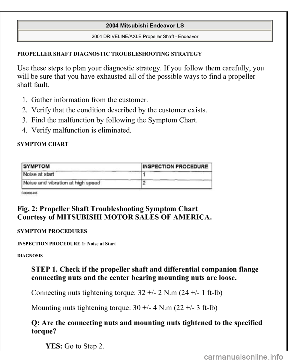
4. Verify malfunction is eliminated. SYMPTOM CHART Fig. 2: Propeller Shaft Troubleshooting Symptom Chart
Courtesy of MITSUBISHI MOTOR SALES OF AMERICA.
SYMPTOM PROCEDURES INSPECTION PROCEDURE 1: Noise at Start DIAGNOSIS
STEP 1. Check if the propeller shaft and differential companion flange
connecting nuts and the center bearing mounting nuts are loose.
Connecting nuts tightening torque: 32 +/- 2 N.m (24 +/- 1 ft-lb)
Mounting nuts tightening torque: 30 +/- 4 N.m (22 +/- 3 ft-lb)
Q: Are the connecting nuts and mounting nuts tightened to the specified
torque?
YES: Go to Ste
p 2.
2004 Mitsubishi Endeavor LS
2004 DRIVELINE/AXLE Propeller Shaft - Endeavor
Page 1086 of 3870
PROPELLER SHAFT REMOVAL AND INSTALLATION Fig. 4: Removing And Installing Propeller Shaft
Courtesy of MITSUBISHI MOTOR SALES OF AMERICA.
REMOVAL SERVICE POINT << A>> PROPELLER SHAFT ASSEMBLY REMOVAL 1. Make mating marks on the differential companion flange and the propeller
shaft assembl
y.
2004 Mitsubishi Endeavor LS
2004 DRIVELINE/AXLE Propeller Shaft - Endeavor
Page 1087 of 3870
Fig. 5: Identifying Mating Marks On Differential Companion Flange And Propeller Shaft Assembly
Courtesy of MITSUBISHI MOTOR SALES OF AMERICA.
2. Insert a rag so as to avoid boot damage, and remove the propeller shaft
assembly in a straight and level manner.
CAUTION: Be careful not to bend the joint assembly when
removing the propeller shaft because this may
cause damage to the joint boot.
2004 Mitsubishi Endeavor LS
2004 DRIVELINE/AXLE Propeller Shaft - Endeavor
Page 1089 of 3870
If reusing the propeller shaft, align the mating marks of differential companion
flan
ge and
propeller shaft assembl
y to install.
Fig. 7: Locating Oil Seal Lips On Transfer Case
Courtes
y of MITSUBISHI MOTOR SALES OF AME
R
Remove oil and grease from the threads of the
mounting bolts and nuts before ti
ghtenin
g, or the
y
loosen. Be careful not to bend the
joint portion when rem
o
the propeller shaft, because this will damage the j
o
boot.
2004 Mitsubishi Endeavor LS
2004 DRIVELINE/AXLE Propeller Shaft - Endeavor
Page 1090 of 3870
Fig. 8: Aligning Mating Marks Of Differential Companion Flange And Propeller Shaft Assembly
Courtesy of MITSUBISHI MOTOR SALES OF AMERICA.
INSPECTION
Check the sleeve yoke and center yoke for wear, damage or cracks. Check the propeller shaft for bends, twisting or damage. Check the universal joint for smooth operation in all directions. Check the center bearing for smooth movement.
PROPELLER SHAFT RUNOUT
Limit: 0.6 mm (0.02 inch)
2004 Mitsubishi Endeavor LS
2004 DRIVELINE/AXLE Propeller Shaft - Endeavor
Page 1096 of 3870

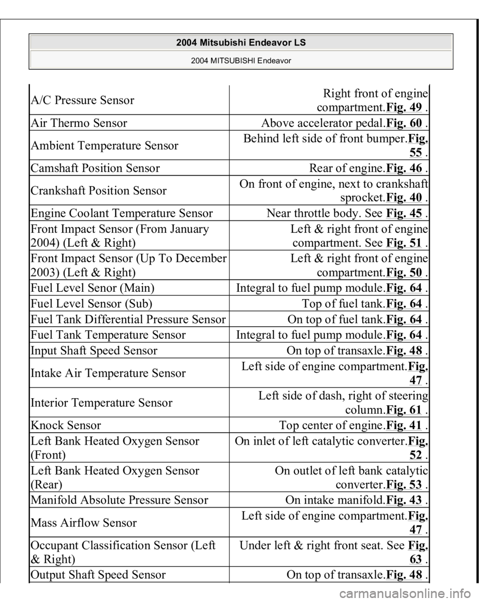
A/C Pressure Sensor
Right front of engine
compartment.Fig. 49
.
Air Thermo Sensor
Above accelerator pedal.Fig. 60
.
Ambient Temperature Sensor
Behind left side of front bumper.Fig.
55 .
Camshaft Position Sensor
Rear of engine.Fig. 46
.
Crankshaft Position Sensor
On front of engine, next to crankshaft
sprocket.Fig. 40
.
Engine Coolant Temperature Sensor
Near throttle body. See Fig. 45
.
Front Impact Sensor (From January
2004) (Left & Right)
Left & right front of engine
compartment. See Fig. 51
.
Front Impact Sensor (Up To December
2003) (Left & Right)
Left & right front of engine
compartment.Fig. 50
.
Fuel Level Senor (Main)
Integral to fuel pump module.Fig. 64
.
Fuel Level Sensor (Sub)
Top of fuel tank.Fig. 64
.
Fuel Tank Differential Pressure Sensor
On top of fuel tank.Fig. 64
.
Fuel Tank Temperature Sensor
Integral to fuel pump module.Fig. 64
.
Input Shaft Speed Sensor
On top of transaxle.Fig. 48
.
Intake Air Temperature Sensor
Left side of engine compartment.Fi
g.
47 .
Interior Temperature Sensor
Left side of dash, right of steering
column.Fig. 61
.
Knock Sensor
Top center of engine.Fig. 41
.
Left Bank Heated Oxygen Sensor
(Front)
On inlet of left catalytic converter.Fi
g.
52 .
Left Bank Heated Oxygen Sensor
(Rear)
On outlet of left bank catalytic
converter.Fig. 53
.
Manifold Absolute Pressure Sensor
On intake manifold.Fig. 43
.
Mass Airflow Sensor
Left side of engine compartment.Fi
g.
47 .
Occupant Classification Sensor (Left
& Right)
Under left & right front seat. See Fi
g.
63 .
Output Shaft Speed Sensor
On top of transaxle.Fig. 48
.
2004 Mitsubishi Endeavor LS
2004 MITSUBISHI Endeavor
Page 2926 of 3870
Fig. 1: Identifying Rear Axle Components
Courtesy of MITSUBISHI MOTOR SALES OF AMERICA.
REAR AXLE DIAGNOSIS INTRODUCTION Noise from the drive shaft or differential may be caused by defects in the
components. TROUBLESHOOTING STRATEGY Use these steps to plan your diagnostic strategy. If you follow them carefully, you
will be sure that you have exhausted most of the possible ways to find a rear axle
fault.
1. Gather information from the customer.
2004 Mitsubishi Endeavor LS
2004 SUSPENSION Rear Axle < AWD > - Endeavor
Page 2929 of 3870
STEP 2. Check the drive shaft for bending.
Q: Is the drive shaft bent?
YES: Replace the drive shaft assembly. Then go to Step 3.
NO: Go to Step 4 .
STEP 3. Check the drive shaft assembly for wear or damage.
Q: Is the drive shaft assembly worn or damaged?
YES: Replace the drive shaft assembly. Then go to Step 4.
NO: There is no action to be taken.
STEP 4. Retest the system.
Q: Is the abnormal noise eliminated?
YES: The procedure is complete.
NO: Start over at Step 1.
INSPECTION PROCEDURE 2: CONSTANT NOISE {{DIFFERENTIAL}} DIAGNOSIS
STEP 1. Check the oil level.
Remove the filler
plug and check the
gear oil level.
2004 Mitsubishi Endeavor LS
2004 SUSPENSION Rear Axle < AWD > - Endeavor