Page 938 of 3870
Courtesy of MITSUBISHI MOTOR SALES OF AMERICA
.
2. Turn the ignition switch to the "ON" position.
3. Check for A/T system diagnostic trouble code. (Refer to HOW TO
READ AND ERASE DIAGNOSTIC TROUBLE CODE
).
4. Turn the ignition switch to the "LOCK" (OFF) position.
5. Disconnect scan tool MB991958.
Q: Is any DTC set?
YES : Diagnose the A/T system. (Refer to DIAGNOSTIC TROUBLE
CODE CHART
). Then go to Step 3.
NO : Replace the PCM. [Refer to POWERTRAIN CONTROL
MODULE (PCM)
]. Then go to Step 3.
STEP 3. Using scan tool MB991958, read the diagnostic trouble code.
1. Connect scan tool MB991958 to the data link connector. (Refer to AUTO
-
CRUISE CONTROL SYSTEM DIAGNOSTIC TROUBLESHOOTING STRATEGY
).
CAUTION: To prevent damage to scan tool MB991958,
always turn the ignition switch to the
"LOCK" (OFF) position before connecting or
disconnecting scan tool MB991958.
2004 Mitsubishi Endeavor LS
2004 BODY & ACCESSORIES Auto, Cruise Control System - Endeavor
Page 953 of 3870

2. Turn the ignition switch to the "ON" position.
3. Set scan tool MB991958 to data reading mode for auto-cruise control
system.
Item 07, Transmission Range Switch.
When selector lever is at the "P" or "N" position, the display on
scan tool MB991958 should be "ON". When selector lever is at the "R" or "D" position, the display on
scan tool MB991958 should be "OFF".
4. Turn the ignition switch to the "LOCK" (OFF) position.
5. Disconnect scan tool MB991958.
Q: Is the switch operating properly?
YES: Go to Step 6.
NO: Refer to SYMPTOM PROCEDURES
. Then go to Step 7 .
STEP 6. Check the Symptoms.
Q: Can auto-cruise control be set?
YES: It can be assumed that this malfunction is intermittent (Refer to
HOW TO COPE WITH INTERMITTENT MALFUNCTIONS
).
NO: Replace the PCM [Refer to POWERTRAIN CONTROL
MODULE (PCM)
]. Then go to Step 7.
STEP 7. Check the symptoms.
Q: Can auto-cruise control be set?
YES: The procedure is complete.
NO: Return to Step 1 .
INSPECTION PROCEDURE 5: Hunting (Repeated Acceleration and Deceleration) Occurs at the Set Vehicle Speed. COMMENT The out
put shaft s
peed sensor si
gnal or the throttle bod
y is sus
pected.
2004 Mitsubishi Endeavor LS
2004 BODY & ACCESSORIES Auto, Cruise Control System - Endeavor
Page 958 of 3870
2. Turn the ignition switch to the "ON" position.
3. Check for MFI system diagnostic trouble code. (Refer to HOW TO
READ AND ERASE DIAGNOSTIC TROUBLE CODE
).
4. Turn the ignition switch to the "LOCK" (OFF) position.
5. Disconnect scan tool MB991958.
Q: Is any DTC set?
YES: Diagnose the MFI control system. (Refer to DIAGNOSTIC
TROUBLE CODE CHART
). Then go to Step 4 .
NO: Go to Step 3.
STEP 3. Retest the system
Q: Does hunting occur?
YES: Replace the PCM [Refer to POWERTRAIN CONTROL
MODULE (PCM)
]. Then go to Step 4.
NO: It can be assumed that this malfunction is intermittent (Refer to
HOW TO COPE WITH INTERMITTENT MALFUNCTIONS
).
STEP 4. Retest the system
Q: Does a hunting occur?
YES: Return to Step 1 .
NO: The procedure is complete.
INSPECTION PROCEDURE 6: Auto-cruise Control Indicator Light inside Combination Meter does not Illuminate.
(However, Auto-cruise Control is Normal).
2004 Mitsubishi Endeavor LS
2004 BODY & ACCESSORIES Auto, Cruise Control System - Endeavor
Page 970 of 3870

Courtesy of MITSUBISHI MOTOR SALES OF AMERICA
.
2. Turn the ignition switch to the "ON" position.
3. Check for MFI system diagnostic trouble code. (Refer to HOW TO
READ AND ERASE DIAGNOSTIC TROUBLE CODE
).
4. Turn the ignition switch to the "LOCK" (OFF) position.
5. Disconnect scan tool MB991958.
Q: Is DTC U1108 set?
YES: Refer to DTC U1108: COMBINATION METER TIME
-OUT
.
Then go to Step 4 .
NO: Go to Step 3.
STEP 3. Retest the system.
Q: Does the "CRUISE" indicator light illuminate when the
"CRUISE" (MAIN) switch is turned "ON"?
YES: It can be assumed that this malfunction is intermittent (Refer to
HOW TO COPE WITH INTERMITTENT MALFUNCTIONS
).
NO: Replace the PCM [Refer to POWERTRAIN CONTROL
MODULE (PCM)
]. Then go to Step 4.
STEP 4. Retest the system.
Q: Does the "CRUISE" indicator light illuminate when the
"CRUISE" (MAIN) switch is turned "ON"?
YES: The procedure is complete.
NO: Return to Step 1 .
DATA LIST REFERENCE TABLE
CAUTION:
When shifting the selector lever to "D" range, the
brakes should be applied so that the vehicle
does not move forward.
2004 Mitsubishi Endeavor LS
2004 BODY & ACCESSORIES Auto, Cruise Control System - Endeavor
Page 1094 of 3870
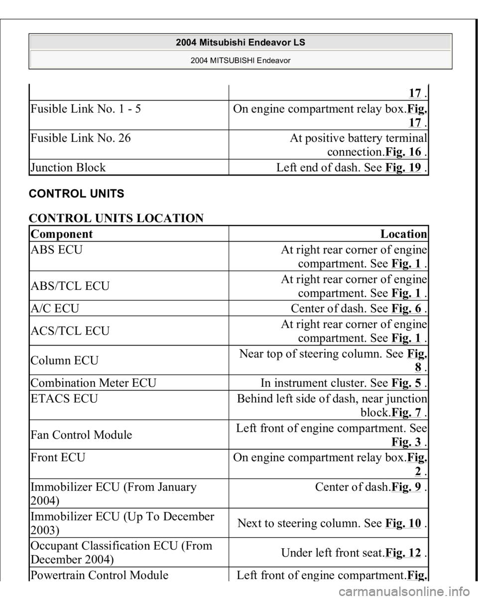
CONTROL UNITS CONTROL UNITS LOCATION
17 .
Fusible Link No. 1 - 5
On engine compartment relay box.Fi
g.
17 .
Fusible Link No. 26
At positive battery terminal
connection.Fig. 16
.
Junction Block
Left end of dash. See Fig. 19
.
Component
Location
ABS ECU
At right rear corner of engine
compartment. See Fig. 1
.
ABS/TCL ECU
At right rear corner of engine
compartment. See Fig. 1
.
A/C ECU
Center of dash. See Fig. 6
.
ACS/TCL ECU
At right rear corner of engine
compartment. See Fig. 1
.
Column ECU
Near top of steering column. See Fi
g. 8 .
Combination Meter ECU
In instrument cluster. See Fig. 5
.
ETACS ECU
Behind left side of dash, near junction
block.Fig. 7
.
Fan Control Module
Left front of engine compartment. See
Fig. 3
.
Front ECU
On engine compartment relay box.Fi
g. 2 .
Immobilizer ECU (From January
2004)
Center of dash.Fig. 9
.
Immobilizer ECU (Up To December
2003)
Next to steering column. See Fig. 10
.
Occupant Classification ECU (From
December 2004)
Under left front seat.Fig. 12
.
Powertrain Control Modul
e
Left front of en
gine com
partment.Fi
g.
2004 Mitsubishi Endeavor LS
2004 MITSUBISHI Endeavor
Page 1199 of 3870
Courtesy of MITSUBISHI MOTOR SALES OF AMERICA
.
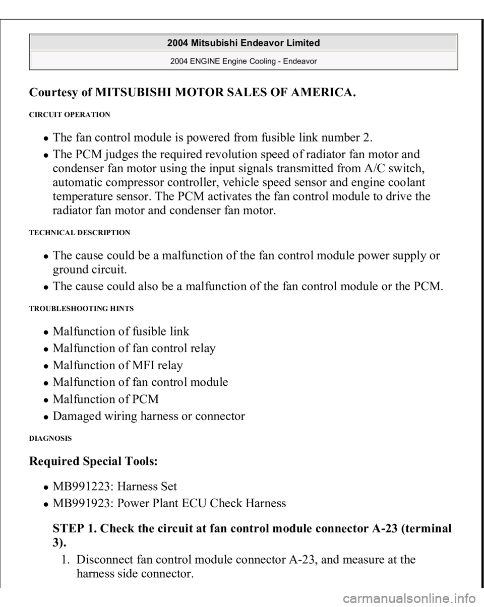
CIRCUIT OPERATION
The fan control module is powered from fusible link number 2. The PCM judges the required revolution speed of radiator fan motor and
condenser fan motor using the input signals transmitted from A/C switch,
automatic compressor controller, vehicle speed sensor and engine coolant
temperature sensor. The PCM activates the fan control module to drive the
radiator fan motor and condenser fan motor.
TECHNICAL DESCRIPTION
The cause could be a malfunction of the fan control module power supply or
ground circuit. The cause could also be a malfunction of the fan control module or the PCM.
TROUBLESHOOTING HINTS
Malfunction of fusible link Malfunction of fan control relay Malfunction of MFI relay Malfunction of fan control module Malfunction of PCM Damaged wiring harness or connector
DIAGNOSIS Required Special Tools:
MB991223: Harness Set MB991923: Power Plant ECU Check Harness
STEP 1. Check the circuit at fan control module connector A-23 (terminal
3).
1. Disconnect fan control module connector A-23, and measure at the
harness side connector.
2004 Mitsubishi Endeavor Limited 2004 ENGINE Engine Cooling - Endeavor
Page 1220 of 3870
Courtesy of MITSUBISHI MOTOR SALES OF AMERICA
.
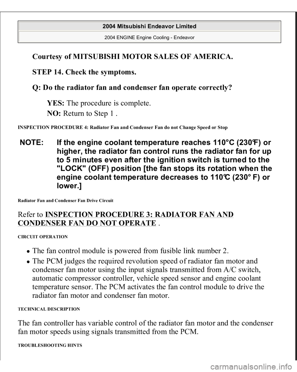
STEP 14. Check the symptoms.
Q: Do the radiator fan and condenser fan operate correctly?
YES: The procedure is complete.
NO: Return to Step 1 .
INSPECTION PROCEDURE 4: Radiator Fan and Condenser Fan do not Change Speed or Stop Radiator Fan and Condenser Fan Drive Circuit Refer to INSPECTION PROCEDURE 3: RADIATOR FAN AND CONDENSER FAN DO NOT OPERATE
.
CIRCUIT OPERATION
The fan control module is powered from fusible link number 2. The PCM judges the required revolution speed of radiator fan motor and
condenser fan motor using the input signals transmitted from A/C switch,
automatic compressor controller, vehicle speed sensor and engine coolant
temperature sensor. The PCM activates the fan control module to drive the
radiator fan motor and condenser fan motor.
TECHNICAL DESCRIPTION The fan controller has variable control of the radiator fan motor and the condenser
fan motor speeds using signals transmitted from the PCM. TROUBLESHOOTING HINTS NOTE: If the engine coolant temperature reaches 110°C (230°F) or
higher, the radiator fan control runs the radiator fan for up
to 5 minutes even after the ignition switch is turned to the
"LOCK" (OFF) position [the fan stops its rotation when the
engine coolant temperature decreases to 110°C (230° F) or
lower.]
2004 Mitsubishi Endeavor Limited 2004 ENGINE Engine Cooling - Endeavor
Page 1221 of 3870
Malfunction of fan control relay Malfunction of fan control module Malfunction of PCM
DIAGNOSIS Required Special Tools:
MB991223: Harness Set MB991923: Power Plant ECU Check Harness
STEP 1. Check the fan control relay.
Refer to FAN CONTROL RELAY CONTINUITY CHECK
.
Q: Is the fan control relay in good condition?
YES: Go to Step 2.
NO: Replace the part, then go to Step 7 .
STEP 2. Check the harness wire between fan control relay connector A-
10X (terminal 2) and fan control module connector A-23 (terminal 3).
2004 Mitsubishi Endeavor Limited 2004 ENGINE Engine Cooling - Endeavor


