Page 1095 of 3870

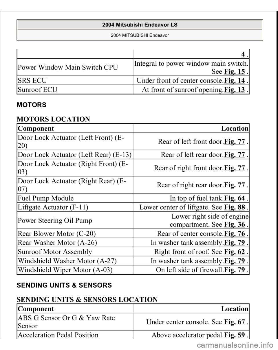
MOTORS MOTORS LOCATION SENDING UNITS & SENSORS SENDING UNITS & SENSORS LOCATION
4 .
Power Window Main Switch CPU
Integral to power window main switch.
See Fig. 15
.
SRS ECU
Under front of center console.Fig. 14
.
Sunroof ECU
At front of sunroof opening.Fig. 13
.
Component
Location
Door Lock Actuator (Left Front) (E-
20)
Rear of left front door.Fig. 77
.
Door Lock Actuator (Left Rear) (E-13)
Rear of left rear door.Fig. 77
.
Door Lock Actuator (Right Front) (E-
03)
Rear of right front door.Fig. 77
.
Door Lock Actuator (Right Rear) (E-
07)
Rear of right rear door.Fig. 77
.
Fuel Pump Module
In top of fuel tank.Fig. 64
.
Liftgate Actuator (F-11)
Lower center of liftgate. See Fig. 88
.
Power Steering Oil Pump
Lower right side of engine
compartment. See Fig. 36
.
Rear Blower Motor (C-20)
Rear of center console.Fig. 76
.
Rear Washer Motor (A-26)
In washer tank assembly.Fig. 79
.
Sunroof Motor Assembly
Right front of roof. See Fig. 62
.
Windshield Washer Motor (A-27)
In washer tank assembly.Fig. 79
.
Windshield Wiper Motor (A-03)
On left side of firewall.Fig. 79
.
Component
Location
ABS G Sensor Or G & Yaw Rate
Sensor
Under center console. See Fig. 67
.
Acceleration Pedal Position
Above accelerator pedal.Fig. 59
.
2004 Mitsubishi Endeavor LS
2004 MITSUBISHI Endeavor
Page 1098 of 3870

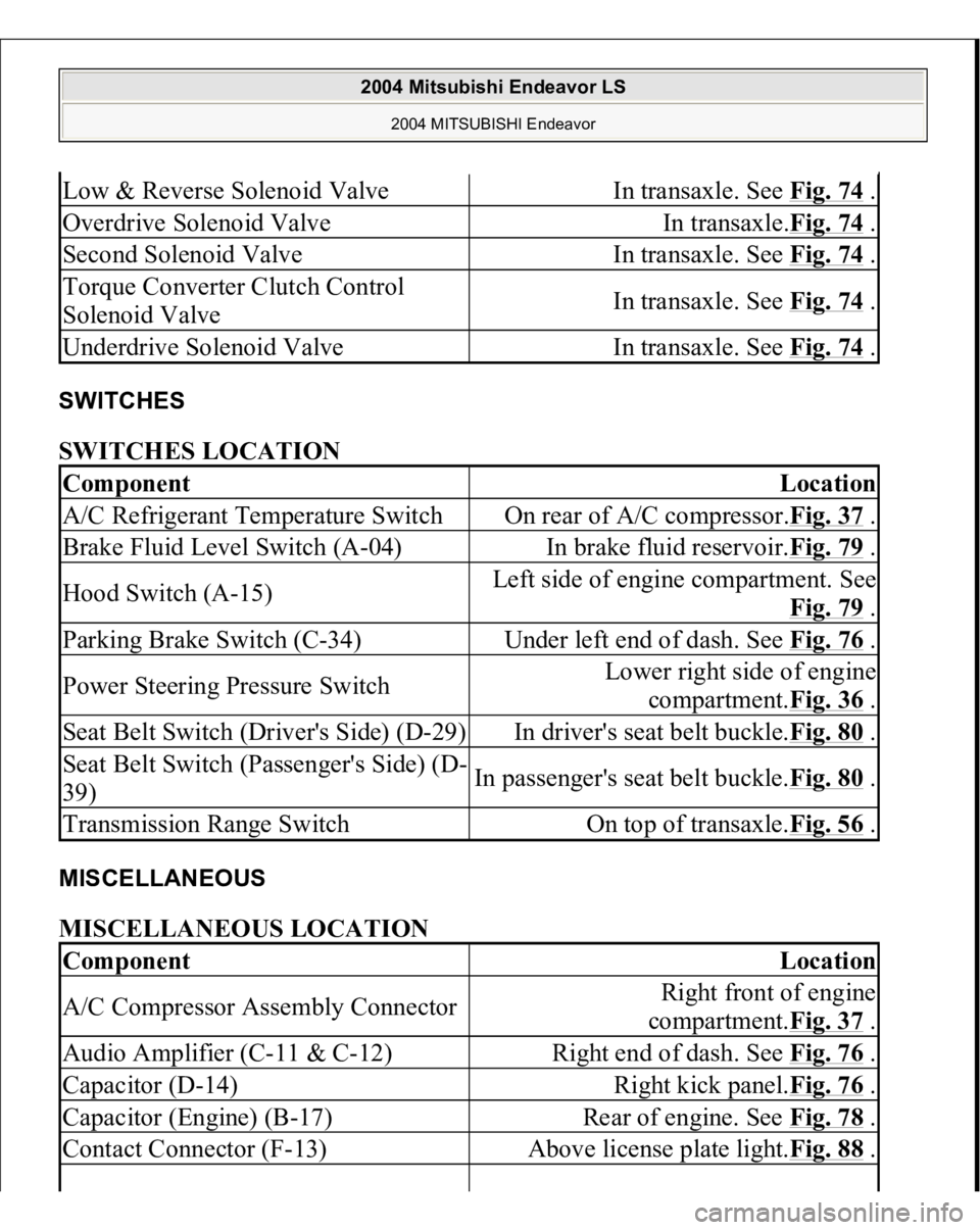
SWITCHES SWITCHES LOCATION MISCELLANEOUS MISCELLANEOUS LOCATION Low & Reverse Solenoid Valve
In transaxle. See Fig. 74
.
Overdrive Solenoid Valve
In transaxle.Fig. 74
.
Second Solenoid Valve
In transaxle. See Fig. 74
.
Torque Converter Clutch Control
Solenoid Valve
In transaxle. See Fig. 74
.
Underdrive Solenoid Valve
In transaxle. See Fig. 74
.
Component
Location
A/C Refrigerant Temperature Switch
On rear of A/C compressor.Fig. 37
.
Brake Fluid Level Switch (A-04)
In brake fluid reservoir.Fig. 79
.
Hood Switch (A-15)
Left side of engine compartment. See
Fig. 79
.
Parking Brake Switch (C-34)
Under left end of dash. See Fig. 76
.
Power Steering Pressure Switch
Lower right side of engine
compartment.Fig. 36
.
Seat Belt Switch (Driver's Side) (D-29)
In driver's seat belt buckle.Fig. 80
.
Seat Belt Switch (Passenger's Side) (D-
39)
In passenger's seat belt buckle.Fig. 80
.
Transmission Range Switch
On top of transaxle.Fig. 56
.
Component
Location
A/C Compressor Assembly Connector
Right front of engine
compartment.Fig. 37
.
Audio Amplifier (C-11 & C-12)
Right end of dash. See Fig. 76
.
Capacitor (D-14)
Right kick panel.Fig. 76
.
Capacitor (Engine) (B-17)
Rear of engine. See Fig. 78
.
Contact Connector (F-13)
Above license plate light.Fig. 88
.
2004 Mitsubishi Endeavor LS
2004 MITSUBISHI Endeavor
Page 1498 of 3870
Fig. 6: Special Tool Chart (4 Of 4)
Courtesy of MITSUBISHI MOTOR SALES OF AMERICA.
ON-VEHICLE SERVICE 7. DRIVE BELTS (FOR GENERATOR, POWER STEERING OIL PUMP AND AIR CONDITIONING)
(CHECK) GENERATOR DRIVE BELT TENSION CHECK < WHEN USING SCAN TOOL MB991958 > Required Special Tools:
MB991958: Scan Tool (MUT-III Sub Assembly) [MB991824: Vehicle
Communication Interface (V.C.I.)] MB991668: Belt Tension Meter Set
CAUTION: To prevent damage to scan tool MB991958, always
2004 Mitsubishi Endeavor Limited
2004 ENGINE Engine - Endeavor
Page 1508 of 3870
Fig. 12: Identifying Standard Value Specification Table
Courtesy of MITSUBISHI MOTOR SALES OF AMERICA.
3. Tighten the tension pulley fixing nut.
Tightening torque: 49+/-10 N.m (36+/-7 ft-lb)
POWER STEERING DRIVE BELT TENSION CHECK Check the drive belt tension by the following procedure. < WHEN USING SCAN TOOL MB991958 > Required Special Tools:
MB991958: Scan Tool (MUT-III Sub Assembly) [MB991824: Vehicle
Communication Interface (V.C.I.)] MB991668: Belt Tension Meter Set NOTE: Because the frequency depends on the belt material,
confirm Part No. shown on the reverse of the belt.
2004 Mitsubishi Endeavor Limited
2004 ENGINE Engine - Endeavor
Page 1541 of 3870
<< D >>POWER STEERING OIL PUMP REMOVAL Remove the power steering oil pump from the engine with the hose attached. << E >>ENGINE MOUNT REMOVAL 1. Support the engine with a garage jack.
Fig. 33: Supporting Engine
Courtesy of MITSUBISHI MOTOR SALES OF AMERICA.
assembly, and secure it with a cord or wire.
NOTE: Place the removed power steering oil pump in a place
where it will not be a hindrance when removing and
installing the engine assembly, and secure it with a cord or
wire.
2004 Mitsubishi Endeavor Limited
2004 ENGINE Engine - Endeavor
Page 1985 of 3870

2004 ELECTRICAL
Fuses & Circuit Breakers - Endeavor
IDENTIFICATION For fuse box locations, see Fig. 1
.
WARNING:Modifications or improper maintenance, including
incorrect removal and installation of the
Supplemental Restraint System (SRS), can
adversely affect system performance. DO NOT
cover, obstruct or change the steering wheel horn
pad in any way, as such action could cause
improper function of the system. Use only plain
water when cleaning the horn pad. Solvents or
cleaners could adversely affect the air bag cover
and cause improper deployment of the system. To
avoid injury from accidental air bag deployment, see
DISABLING & ACTIVATING AIR BAG SYSTEM in AIR
BAG RESTRAINT SYSTEMS article in GENERAL
INFORMATION.
WARNING:When battery is disconnected, vehicles equipped
with computers may lose memory data. When
battery power is restored, driveability problems may
exist on some vehicles. These vehicles may require
a relearn procedure. See COMPUTER RELEARN
PROCEDURES article in GENERAL INFORMATION.
CAUTION: Disconnect negative battery cable before servicing
any air bag system, steering column or passenger
side dash component. After any repair, turn ignition
key to the ON position from passenger's side of
vehicle in case of accidental air bag inflation.
2004 Mitsubishi Endeavor Limited
2004 ELECTRICAL Fuses & Circuit Breakers - Endeavor
2004 Mitsubishi Endeavor Limited
2004 ELECTRICAL Fuses & Circuit Breakers - Endeavor
Page 2364 of 3870
Fig. 273: Voltage Of A/C Pressure Sensor
Courtesy of MITSUBISHI MOTOR SALES OF AMERICA.
COMPRESSOR DRIVE BELT ADJUSTMENT Refer to
7. DRIVE BELTS (FOR GENERATOR, POWER STEERING OIL
PUMP AND AIR CONDITIONING
.
CHARGING Use the refrigerant recovery station to charge the refrigerant. METHOD BY USING REFRIGERANT RECOVERY AND RECYCLING UNIT Using the refrigerant recovery and recycling unit, refill the refrigerant. NOTE: Refer to the REFRIGERANT RECOVERY AND RECYCLING
UNIT'S INSTRUCTION MANUAL FOR OPERATION OF THE
2004 Mitsubishi Endeavor LS
2004 HVAC Heater Air Conditioning, Ventilation - Endeavor
Page 2371 of 3870

weather, vehicle speed, in gear or neutral, engine temperature or any other special
conditions. Noises that develop during A/C operation can often be misleading. For example:
what sounds like a failed front bearing or connecting rod, may be caused by loose
bolts, nuts, mounting brackets, or a loose clutch assembly. Verify accessory drive
belt tension (power steering or generator).
Improper accessory drive belt tension can cause a misleading noise when the
compressor is engaged and little or no noise when the compressor is disengaged.
Drive belts are speed-sensitive. That is, at different engine speeds, and depending
upon belt tension, belts can develop unusual noises that are often mistaken for
mechanical problems within the compressor. HANDLING TUBING AND FITTINGS Kinks in the refrigerant tubing or sharp bends in the refrigerant hose lines will
greatly reduce the capacity of the entire system. High pressures are produced in the
system when it is operating. Extreme care must be exercised to make sure that all
connections are pressure tight. Dirt and moisture can enter the system when it is
opened for repair or replacement of lines or components. The following precautions
must be observed. The system must be completely discharged before opening any
fitting of connection in the refrigeration system. Open fittings with caution even
after the system has been discharged. If any pressure is noticed as a fitting is
loosened, allow trapped pressure to bleed off very slowly. Never attempt to rebend formed lines to fit. Use the correct line for the installation
you are servicing. A good rule for the flexible hose lines is keep the radius of all
bends at least 10 times the diameter of the hose.
Sharper bends will reduce the flow of refrigerant. The flexible hose lines should be
routed so that they are at least 80 mm (3.1 inches) from the exhaust manifold. It is
good practice to inspect all flexible hose lines at least once a year to make sure they
are in good condition and properly routed.
On standard
plumbin
g fittin
gs with O-rin
gs, these O-rin
gs are not reusable.
2004 Mitsubishi Endeavor LS
2004 HVAC Heater Air Conditioning, Ventilation - Endeavor