Page 394 of 3870
1. Connect scan tool to Data Link Connector (DLC). See INITIAL SRS
DIAGNOSTIC PROCEDURE
under DIAGNOSTICS. If scan tool is able to
diagnose CAN bus lines and CAN bus lines are satisfactory, go to next step. If
scan tool cannot diagnose CAN bus lines, repair CAN bus lines. Go to next
step.
2. Erase, then retrieve DTCs. If DTC B1475 is retrieved, replace SRS ECU. See
SRS ELECTRONIC CONTROL UNIT (SRS ECU)
under REMOVAL &
INSTALLATION. If DTC B1475 is not retrieved, an intermittent condition
may exist.
DTCB1476: POWER SUPPLY VOLTAGE DROPS ABNORMALLY 1. Connect scan tool to Data Link Connector (DLC). See INITIAL SRS
DIAGNOSTIC PROCEDURE
under DIAGNOSTICS. If scan tool is able to
diagnose CAN bus lines and CAN bus lines are satisfactory, go to next step. If
scan tool cannot diagnose CAN bus lines, repair CAN bus lines. Go to next
step.
2. Erase, then retrieve DTCs. Turn ignition off. If DTC B1476 is retrieved, go to
next step. If DTC B1476 is not retrieved, an intermittent condition may exist.
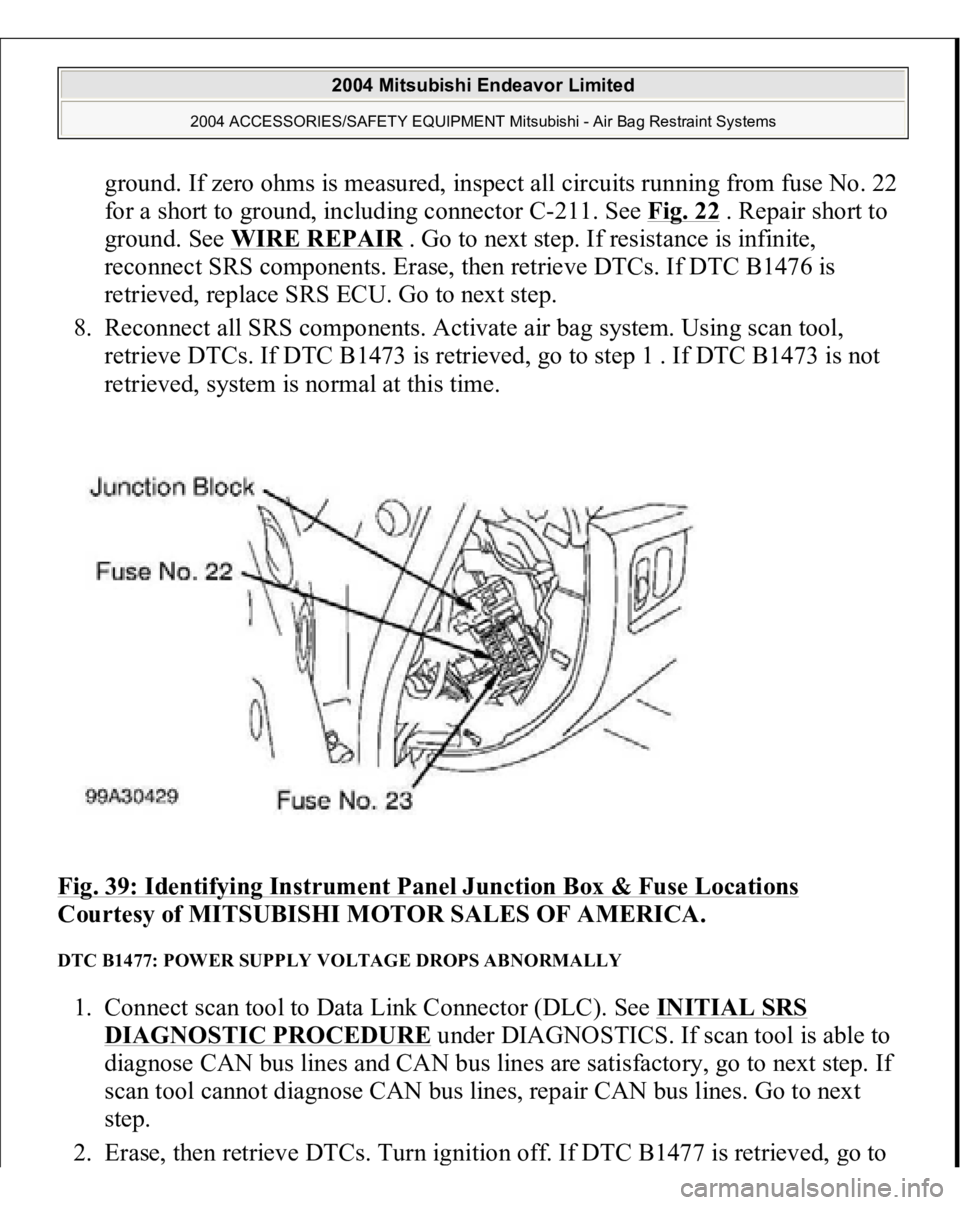
3. Remove fuse No. 22 from instrument panel junction block. See Fig. 39
. If fuse
is blown, go to step 6 . If fuse is not blown, go to next step.
4. Disconnect negative battery cable. Disconnect SRS ECU connector C-26. See
SRS ELECTRONIC CONTROL UNIT (SRS ECU)
under REMOVAL &
INSTALLATION. See Fig. 30
. Connect negative battery cable. Turn ignition
on. Measure voltage between ground and SRS ECU connector C-26, terminal
No. 23 (Black/White wire). If voltage is 9 volts or more, reconnect SRS
components. Erase, then retrieve DTCs. If DTC B1476 is retrieved, replace
SRS ECU. Go to step 8 . If DTC B1476 is not retrieved, go to next step.
5. Inspect Black/White wire between SRS ECU connector C-26, terminal No. 23
and ignition switch connector C-308, terminal No. 2. If wire is okay, go to step
8 . If wire is not okay, replace harness between SRS ECU and ignition switch.
Go to step 8 .
6. Replace fuse. Turn ignition on for one minute, then turn off. Inspect fuse. If
fuse is okay, go to step 8 . If fuse is not okay, go to next step.
7. Measure resistance between SRS ECU connector C-26
, terminal No. 23 and
2004 Mitsubishi Endeavor Limited
2004 ACCESSORIES/SAFETY EQUIPMENT Mitsubishi - Air Bag Restraint Systems
Page 395 of 3870
ground. If zero ohms is measured, inspect all circuits running from fuse No. 22
for a short to ground, including connector C-211. See Fig. 22
. Repair short to
ground. See WIRE REPAIR
. Go to next step. If resistance is infinite,
reconnect SRS components. Erase, then retrieve DTCs. If DTC B1476 is
retrieved, replace SRS ECU. Go to next step.
8. Reconnect all SRS components. Activate air bag system. Using scan tool,
retrieve DTCs. If DTC B1473 is retrieved, go to step 1 . If DTC B1473 is not
retrieved, system is normal at this time.
Fig. 39: Identifying Instrument Panel Junction Box & Fuse Locations
Courtesy of MITSUBISHI MOTOR SALES OF AMERICA.
DTC B1477: POWER SUPPLY VOLTAGE DROPS ABNORMALLY 1. Connect scan tool to Data Link Connector (DLC). See INITIAL SRS
DIAGNOSTIC PROCEDURE
under DIAGNOSTICS. If scan tool is able to
diagnose CAN bus lines and CAN bus lines are satisfactory, go to next step. If
scan tool cannot diagnose CAN bus lines, repair CAN bus lines. Go to next
step.
2. Erase, then retrieve DTCs. Turn ignition off. If DTC B1477 is retrieved,
go to
2004 Mitsubishi Endeavor Limited
2004 ACCESSORIES/SAFETY EQUIPMENT Mitsubishi - Air Bag Restraint Systems
Page 396 of 3870
next step. If DTC B1477 is not retrieved, an intermittent condition may exist.
3. Remove fuse No. 23 from instrument panel junction block. See Fig. 39
. If fuse
is blown, go to step 6 . If fuse is not blown, go to next step.
4. Disconnect negative battery cable. Disconnect SRS ECU connector C-26. See
SRS ELECTRONIC CONTROL UNIT (SRS ECU)
under REMOVAL &
INSTALLATION. See Fig. 30
. Connect negative battery cable. Turn ignition
on. Measure voltage between ground and SRS ECU connector C-26, terminal
No. 24 (Black/Yellow wire). If voltage is 9 volts or more, reconnect SRS
components. Erase, then retrieve DTCs. If DTC B1477 is retrieved, replace
SRS ECU. Go to step 8 . If DTC B1477 is not retrieved, go to next step.
5. Inspect Black/Yellow wire between SRS ECU connector C-26, terminal No. 24
and ignition switch connector C-308, terminal No. 2. See WIRING
DIAGRAMS
. If wire is okay, go to step 8 . If wire is not okay, replace
harness between SRS ECU and ignition switch. Go to step 8 .
6. Replace fuse. Turn ignition on for one minute, then turn off. Inspect fuse. If
fuse is okay, go to step 8 . If fuse is not okay, go to next step.
7. Measure resistance between SRS ECU connector terminal No. 24 and ground.
If zero ohms is measured, inspect all circuits running from fuse No. 23 for a
short to ground. including connector C-211. See Fig. 22
. Repair short to
ground. See WIRE REPAIR
. Go to next step. If continuity does not exist,
reconnect SRS components. Erase, then retrieve DTCs. If DTC B1477 is
retrieved, replace SRS ECU. Go to next step.
8. Reconnect all SRS components. Activate air bag system. Using scan tool,
retrieve DTCs. If DTC B1473 is retrieved, go to step 1 . If DTC B1473 is not
retrieved, system is normal at this time.
DTC B1478: SRS ECU CAPACITOR CIRCUIT VOLTAGE HIGH 1. Connect scan tool to Data Link Connector (DLC). See INITIAL SRS
DIAGNOSTIC PROCEDURE
under DIAGNOSTICS. If scan tool is able to
diagnose CAN bus lines and CAN bus lines are satisfactory, go to next step. If
scan tool cannot diagnose CAN bus lines, repair CAN bus lines. Go to next
step.
2. Erase, then retrieve DTCs. If DTC B1478 is retrieved, replace SRS ECU. See
SRS ELECTRONIC CONTROL UNIT (SRS ECU)
under REMOVAL &
2004 Mitsubishi Endeavor Limited
2004 ACCESSORIES/SAFETY EQUIPMENT Mitsubishi - Air Bag Restraint Systems
Page 792 of 3870
2004 ENGINE COOLING
Electric Cooling Fans - Endeavor
DESCRIPTION & OPERATION The fan control module is powered from fusible link No. 2. See Fig. 1
. The PCM
judges the required revolution speed of radiator fan motor and condenser fan motor
using input signals transmitted from the A/C switch, automatic compressor
controller, vehicle speed sensor and engine coolant temperature sensor. The PCM
activates the fan control module to drive the radiator fan motor and condenser fan
motor. COMPONENT LOCATIONS COMPONENT LOCATIONS Component
Location
Condenser Fan
(1) Behind Radiator
Fan Control Module
(1) Integrated With Radiator Fan Motor
Fan Control Relay
In Engine Compartment Fuse/Relay
Box
Fusible Link No. 2
(2) In Engine Compartment Fuse/Relay
Box
Multi-Port Fuel Injection (MFI) Relay
In Engine Compartment Fuse/Relay
Box
Radiator Fan
(1) Behind Radiator
(1)
See Fig. 13
.
(2)
See Fig. 1
.
2004 Mitsubishi Endeavor Limited
2004 ENGINE COOLING Electric Cooling Fans - Endeavor
2004 Mitsubishi Endeavor Limited
2004 ENGINE COOLING Electric Cooling Fans - Endeavor
Page 911 of 3870
Fig. 65: Checking Harness Wire
Courtesy of MITSUBISHI MOTOR SALES OF AMERICA.
Q: Is the harness wire in good condition?
YES : Go to Step 14.
NO : Repair the damaged harness wire. Then go to Step 22 .
STEP 14. Check the fuse number 11 at the relay box in engine
compartment.
2004 Mitsubishi Endeavor LS
2004 BODY & ACCESSORIES Auto, Cruise Control System - Endeavor
Page 912 of 3870
Fig. 66: Checking Fuse Number 11
Courtesy of MITSUBISHI MOTOR SALES OF AMERICA.
Q: Is the fuse in good condition?
YES : It can be assumed that this malfunction is intermittent. (Refer to
HOW TO COPE WITH INTERMITTENT MALFUNCTIONS
).
Then go to Step 22 .
NO : Replace the fuse. Then go to Step 22 .
STEP 15. Measure the terminal voltage at PCM connector B-19.
1. Disconnect all the connectors from the PCM.
2004 Mitsubishi Endeavor LS
2004 BODY & ACCESSORIES Auto, Cruise Control System - Endeavor
Page 1017 of 3870
Fig. 13: Identifying Run Channel, Lower Sash And Door Sas
h
Courtesy of MITSUBISHI MOTOR SALES OF AMERICA.
5. If repair or adjustment is not possible, replace the door assembly.
POWER WINDOW TIMER FUNCTION CHECK After the doors are closed and the ignition switch is turned to the "LOCK" (OFF)
position, the power windows should work within 30 seconds. The timer expires if
the front door is opened during that 30 second time. If it does not, carry out the
timer troubleshooting in SYMPTOM CHART
.
POWER WINDOW OPERATING CURRENT CHECK 1. Remove the power window fuse and connect an ammeter as shown in the
illustration.
2. When the power window switch is pressed in the "UP" position, a large amoun
t
of current flows from the time the window starts to close until it is fully closed,
Measure the current during this time
Standard value (A): 5 +/-1A [Power supply voltage 14.5 +/-0.5V, 25°C (77°
F)]
3. If the operation current is outside the standard value, refer to INPUT SIGNAL
CHART
.
2004 Mitsubishi Endeavor LS
2004 BODY & ACCESSORIES Door - Endeavor
Page 1018 of 3870
Fig. 14: Checking Power Window Fuse Voltage
Courtesy of MITSUBISHI MOTOR SALES OF AMERICA.
POWER WINDOW RELAY CHECK POWER WINDOW RELAY CHECK SPECIFICATION BATTERY VOLTAGE
TESTER CONNECTION
SPECIFIED
CONDITION
Not applied
4-5
Open circuit
Connect terminal
No. 3 and the
negative battery
terminal. Connect terminal
No. 1 and the
positive battery
4-5
Less than 2 ohms
2004 Mitsubishi Endeavor LS
2004 BODY & ACCESSORIES Door - Endeavor