Page 1097 of 3870

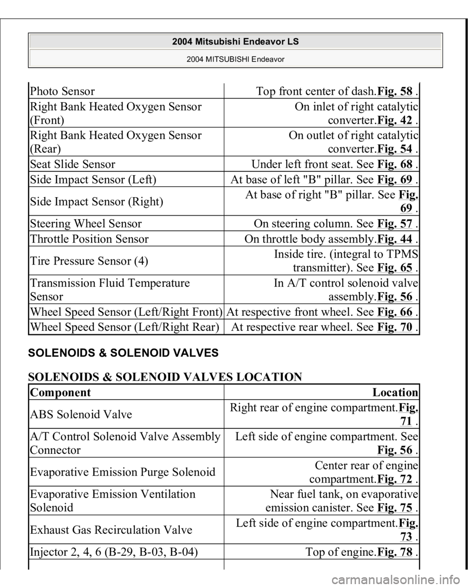
SOLENOIDS & SOLENOID VALVES SOLENOIDS & SOLENOID VALVES LOCATION Photo Sensor
Top front center of dash.Fig. 58
.
Right Bank Heated Oxygen Sensor
(Front)
On inlet of right catalytic
converter.Fig. 42
.
Right Bank Heated Oxygen Sensor
(Rear)
On outlet of right catalytic
converter.Fig. 54
.
Seat Slide Sensor
Under left front seat. See Fig. 68
.
Side Impact Sensor (Left)
At base of left "B" pillar. See Fig. 69
.
Side Impact Sensor (Right)
At base of right "B" pillar. See Fig.
69 .
Steering Wheel Sensor
On steering column. See Fig. 57
.
Throttle Position Sensor
On throttle body assembly.Fig. 44
.
Tire Pressure Sensor (4)
Inside tire. (integral to TPMS
transmitter). See Fig. 65
.
Transmission Fluid Temperature
Sensor
In A/T control solenoid valve
assembly.Fig. 56
.
Wheel Speed Sensor (Left/Right Front)
At respective front wheel. See Fig. 66
.
Wheel Speed Sensor (Left/Right Rear)
At respective rear wheel. See Fig. 70
.
Component
Location
ABS Solenoid Valve
Right rear of engine compartment.Fig.
71 .
A/T Control Solenoid Valve Assembly
Connector
Left side of engine compartment. See
Fig. 56
.
Evaporative Emission Purge Solenoid
Center rear of engine
compartment.Fig. 72
.
Evaporative Emission Ventilation
Solenoid
Near fuel tank, on evaporative
emission canister. See Fig. 75
.
Exhaust Gas Recirculation Valve
Left side of engine compartment.Fig.
73 .
Injector 2, 4, 6 (B-29, B-03, B-04)
Top of engine.Fig. 78
.
2004 Mitsubishi Endeavor LS
2004 MITSUBISHI Endeavor
Page 1202 of 3870
NO: Replace it, then go to Step 1 .
STEP 3. Check the MFI relay.
Refer to MULTIPORT FUEL INJECTION (MFI) RELAY AND
THROTTLE ACTUATOR CONTROL MOTOR RELAY CONTINUITY CHECK
.
Q: Is the MFI relay in good condition?
YES: Go to Step 4.
NO: Replace it, then go to Step 1 .
STEP 4. Check for harness dama
ge between fusible link number 2 and fan
control relay connector A-10X (terminal 4).
Fi
g. 10: Checkin
g Harness Dama
ge
2004 Mitsubishi Endeavor Limited 2004 ENGINE Engine Cooling - Endeavor
Page 1302 of 3870

cleaned regularly and kept separate from personal clothing. Where there is a risk of eye contact, eye protection should be worn i.e.
chemical goggles or face shields. In addition, an eye wash facility should be
provided. Obtain First Aid treatment immediately for open cuts and wounds. Wash regularly with soap and water to ensure all oil is removed, especially
before meals (skin cleansers and nail brushes will help). After cleaning, apply
lotion, etc., containing lanolin to replace natural skin oils is advised. Do not use gasoline, kerosene, diesel fuel, gas oil, thinner or solvents for
cleaning skin. Apply barrier creams before each work period to help clean the skin after
work. If skin disorders develop, obtain medical advice immediately.
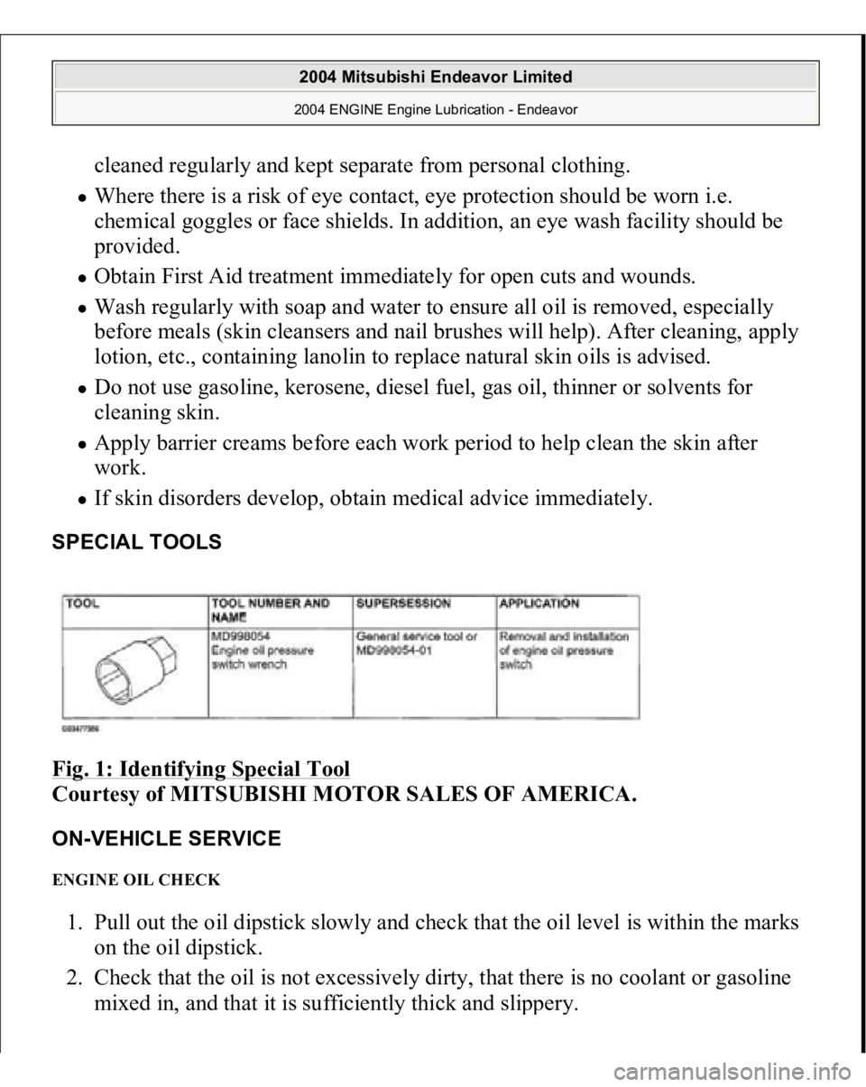
SPECIAL TOOLS Fig. 1: Identifying Special Tool
Courtesy of MITSUBISHI MOTOR SALES OF AMERICA.
ON-VEHICLE SERVICE ENGINE OIL CHECK 1. Pull out the oil dipstick slowly and check that the oil level is within the marks
on the oil dipstick.
2. Check that the oil is not excessively dirty, that there is no coolant or gasoline
mixed in, and that it is sufficientl
y thick and sli
ppery.
2004 Mitsubishi Endeavor Limited 2004 ENGINE Engine Lubrication - Endeavor
Page 1360 of 3870
Standard value: 1.0 mm (0.03 inch) or less
Fig. 39: Measuring The Movement Of The Rod
Courtesy of MITSUBISHI MOTOR SALES OF AMERICA.
INTAKE MANIFOLD AND FUEL PARTS REMOVAL AND INSTALLATION < UP TO DECEMBER 2003 >
2004 Mitsubishi Endeavor Limited 2004 ENGINE Engine Overhaul - Endeavor
Page 1361 of 3870
Fig. 40: Removing/Installing Intake Manifold And Fuel Parts
Courtesy of MITSUBISHI MOTOR SALES OF AMERICA.
< FROM JANUARY 2004 >
2004 Mitsubishi Endeavor Limited 2004 ENGINE Engine Overhaul - Endeavor
Page 1362 of 3870
Fig. 41: Removing/Installing Intake Manifold And Fuel Parts (2 Of 2)
Courtesy of MITSUBISHI MOTOR SALES OF AMERICA.
INSTALLATION SERVICE POINTS
>>A<< INTAKE MANIFOLD INSTALLATION 1. Ti
ghten the nuts "R" to 6.5+
/-1.5 N.m
(57+
/-13 i
n-lb
).
2004 Mitsubishi Endeavor Limited 2004 ENGINE Engine Overhaul - Endeavor
Page 1364 of 3870
Tightening torque: 22+/-1 N.m (16+/-1 ft-lb)
>>B<< INJECTOR INSTALLATION 1. Apply clean engine oil to the O-ring.
2. Insert the injector into the fuel rail.
Fig. 43: Installing Injector
Courtesy of MITSUBISHI MOTOR SALES OF AMERICA.
3. Make sure the injector rotates smoothly. If not, remove the injector to check
the O-ring for damage, and replace the O-ring if necessary. Then reinsert the
injector and check that it rotates smoothly.
4. Confirm the
protrusion of in
jector is at center. I
f not
, rotate the in
jector fo
r
CAUTION: Use care not to let engine oil enter the fuel rail.
2004 Mitsubishi Endeavor Limited 2004 ENGINE Engine Overhaul - Endeavor
Page 1365 of 3870
protrusion to be center.
Fig. 44: Checking Protrusion Of Injector
Courtesy of MITSUBISHI MOTOR SALES OF AMERICA.
>>C<< INJECTOR AND FUEL RAIL INSTALLATION 1. Apply clean engine oil to the O-ring.
2. Insert the fuel pressure regulator into the fuel rail.
3. Make sure the regulator rotates smoothly. If not, remove the fuel pressure
regulator to check the O-ring for damage, and replace the O-ring if necessary.
Then reinsert the fuel pressure regulator and chec
k that it rotates smoothly.
CAUTION: Do not let engine oil enter the fuel rail.
2004 Mitsubishi Endeavor Limited 2004 ENGINE Engine Overhaul - Endeavor