2004 MITSUBISHI ENDEAVOR ignition
[x] Cancel search: ignitionPage 331 of 3870
If DTC 54 or 55 is present, replace SRS ECU. See SRS ELECTRONIC CONTROL UNIT (SRS ECU)
under REMOVAL & INSTALLATION.
DTC 56 & 57: DRIVER-SIDE SEAT BELT PRETENSIONER If DTC 56 or 57 is present, replace SRS ECU. See SRS ELECTRONIC CONTROL UNIT (SRS ECU)
under REMOVAL & INSTALLATION.
DTC 58 & 59: PASSENGER-SIDE SEAT BELT PRETENSIONER If DTC 58 or 59 is present, replace SRS ECU. See SRS ELECTRONIC CONTROL UNIT (SRS ECU)
under REMOVAL & INSTALLATION.
DTC 61: DRIVER-SIDE AIR BAG MODULE SHORT TO VOLTAGE 1. Before proceeding, see AIR BAG SAFETY PRECAUTIONS
. Disable air
bag system. See DISABLING & ACTIVATING AIR BAG SYSTEM
. Go
to next step.
2. Disconnect clockspring connector C-305. See DRIVER
-SIDE AIR BAG
MODULE & CLOCKSPRING
under REMOVAL & INSTALLATION. See
Fig. 19
. Connect Load Resistor (MB991865) to Load Resistor Harness
(MB991866). Connect load resistor harness to clockspring connector C-305 by
backprobing connector. Connect negative battery cable. Using scan tool, check
for DTCs. If DTC 61 is retrieved, go to next step. If DTC 61 is not retrieved,
replace driver-side air bag module. Go to step 5 .
3. Disconnect negative battery cable. Disconnect clockspring connector C-307.
Connect load resistor and load resistor harness to clockspring connector C-307,
terminals No. 3 and 4 by backprobing connector. See Fig. 24
. Connect
negative battery cable. Using scan tool check for DTCs. If DTC 61 is retrieved,
go to next step. If DTC 61 is not retrieved, replace clockspring. Go to step 5 .
4. Disconnect SRS ECU connector C-26. Disconnect clockspring connector C-
307. Turn ignition on. Measure voltage between ground and SRS ECU
connector C-26, terminal No. 11 (Yellow/Black wire) and No. 12 (Yellow
wire). If voltage is measured at either terminal, replace wire harness. Go to
next step. If voltage is not measured, reconnect SRS components. Using scan
tool, erase then retrieve DTCs. If DTC 61 is retrieved, replace SRS ECU. Go to
next ste
p. If DTC 61 is not retrieved,
go to next ste
p.
2004 Mitsubishi Endeavor Limited
2004 ACCESSORIES/SAFETY EQUIPMENT Mitsubishi - Air Bag Restraint Systems
Page 333 of 3870
19 . Connect Load Resistor (MB991865) to Load Resistor Harness
(MB991866). Connect load resistor harness to connector C-09 by backprobing
connector. Connect negative battery cable. Using scan tool, erase then retrieve
DTCs. If DTC 64 is retrieved, go to next step. If DTC 64 is not retrieved,
replace passenger-side impact air bag module. Go to step 3 .
2. Disconnect SRS ECU connector C-26 and passenger-side air bag module
connector C-09. See SRS ELECTRONIC CONTROL UNIT (SRS ECU)
under REMOVAL & INSTALLATION. Turn ignition on. Check for voltage
between ground and connector C-26, terminal No. 9 (Yellow/Green wire) and
No. 10 (Yellow/Red wire). If voltage is measured in either wire, replace wire
harness. Go to next step. If voltage is not measured in either wire, erase, then
retrieve DTCs. If DTC 64 is retrieved, replace SRS ECU. Go to next step.
3. Reconnect all SRS components. Activate air bag system. Using scan tool, erase
then retrieve DTCs. If DTC 64 is retrieved, go to step 1 . If DTC 64 is not
retrieved, system is normal at this time. Intermittent condition may exist.
DTC 65: PASSENGER-SIDE AIR BAG MODULE SHORT TO GROUND 1. Before proceeding, see AIR BAG SAFETY PRECAUTIONS
. Disable air
bag system. See DISABLING & ACTIVATING AIR BAG SYSTEM
.
Disconnect passenger-side air bag module connector C-09. See PASSENGER
-
SIDE AIR BAG MODULE
under REMOVAL & INSTALLATION. See Fi
g.
19 . Connect Load Resistor (MB991865) to Load Resistor Harness
(MB991866). Connect load resistor harness to connector C-09 by backprobing
connector. Connect negative battery cable. Using scan tool, erase then retrieve
DTCs. If DTC 65 is retrieved, go to next step. If DTC 65 is not retrieved,
replace passenger-side impact air bag module. Go to step 3 .
2. Disconnect SRS ECU connector C-26 and passenger-side air bag module
connector C-09. See SRS ELECTRONIC CONTROL UNIT (SRS ECU)
under REMOVAL & INSTALLATION. Check for continuity between ground
and connector C-26, terminal No. 9 (Yellow/Green wire) and No. 10
(Yellow/Red wire). If continuity exists, replace wire harness between SRS
ECU and passenger-side air bag module. Go to next step. If continuity does not
exist, erase then retrieve DTCs. If DTC 65 is retrieved, replace SRS ECU. Go
to next ste
p.
2004 Mitsubishi Endeavor Limited
2004 ACCESSORIES/SAFETY EQUIPMENT Mitsubishi - Air Bag Restraint Systems
Page 334 of 3870
3. Reconnect all SRS components. Activate air bag system. Using scan tool, erase
then retrieve DTCs. If DTC 65 is retrieved, go to step 1 . If DTC 65 is not
retrieved, system is normal at this time. Intermittent condition may exist. DTC 66: DRIVER-SIDE SEAT BELT PRETENSIONER SHORT TO VOLTAGE 1. Before proceeding, see AIR BAG SAFETY PRECAUTIONS
. Disable air
bag system. See DISABLING & ACTIVATING AIR BAG SYSTEM
. Go
to next step.
2. Disconnect driver-side seat belt pretensioner connector D-24. See SEAT
BELT PRETENSIONER
under REMOVAL & INSTALLATION. See Fig.
19 . Connect Load Resistor (MB991865) to Load Resistor Harness
(MB991884). Connect load resistor harness to connector D-24. Connect
negative battery cable. Using scan tool, erase then retrieve DTCs. If DTC 66 is
retrieved, go to next step. If DTC 66 is not retrieved, replace driver-side seat
belt pretensioner. Go to step 4 .
3. Turn ignition off. Disconnect SRS ECU connector C-25. See SRS ELECTRONIC CONTROL UNIT (SRS ECU)
under REMOVAL &
INSTALLATION. Remove load resistor harness from driver-side seat belt
pretensioner connector D-24. Turn ignition on. Measure voltage between
ground and SRS ECU connector C-25, terminal No. 29 (Red/Blue wire) and
No. 30 (Red/Yellow wire). If voltage is measured at either terminal, replace
wire harness between SRS ECU and seat belt pretensioner. Go to next step. If
voltage is not measured at either terminal, reconnect SRS components. Using
scan tool, erase then retrieve DTCs. If DTC 66 is retrieved, replace SRS ECU.
Go to next step.
4. Reconnect all SRS components. Using scan tool, check for DTCs. If DTC 66 is
retrieved, go to step 1 . If DTC 66 is not retrieved, system is normal at this
time. Intermittent condition may exist.
DTC 67: DRIVER-SIDE SEAT BELT PRETENSIONER SHORT TO GROUND 1. Before proceeding, see AIR BAG SAFETY PRECAUTIONS
. Disable air
bag system. See DISABLING & ACTIVATING AIR BAG SYSTEM
. Go
to next step.
2. Disconnect drive
r-side seat belt
pretensioner connector D-24. See SEAT
2004 Mitsubishi Endeavor Limited
2004 ACCESSORIES/SAFETY EQUIPMENT Mitsubishi - Air Bag Restraint Systems
Page 335 of 3870
BELT PRETENSIONE
R under REMOVAL & INSTALLATION. See Fig.
18 . Connect Load Resistor (MB991866) to Load Resistor Harness
(MB991884). Connect Load Resistor Harness to connector D-24. Connect
negative battery cable. Using scan tool, erase then retrieve DTCs. If DTC 67 is
retrieved, go to next step. If DTC 67 is not retrieved, replace driver-side seat
belt pretensioner. Go to step 4 .
3. Disconnect SRS ECU connector C-25. See SRS ELECTRONIC CONTROL UNIT (SRS ECU)
under REMOVAL & INSTALLATION. Remove load
resistor harness from driver-side seat belt pretensioner connector D-24.
Measure continuity between ground and SRS ECU connector C-25, terminal
No. 29 (Red/Blue wire) and No. 30 (Red/Yellow wire). If continuity is not
found in either circuit, erase then retrieve DTCs. If DTC 67 is retrieved,
replace SRS ECU. Go to next step. If continuity is found in either circuit,
replace wire harness between SRS ECU and driver-side seat belt pretensioner.
Go to next step.
4. Reconnect all SRS components. Using scan tool, check for DTCs. If DTC 67 is
retrieved, go to step 1 . If DTC 67 is not retrieved, system is normal at this
time. Intermittent condition may exist.
DTC 68: PASSENGER-SIDE SEAT BELT PRETENSIONER SHORT TO VOLTAGE 1. Before proceeding, see AIR BAG SAFETY PRECAUTIONS
. Disable air
bag system. See DISABLING & ACTIVATING AIR BAG SYSTEM
. Go
to next step.
2. Disconnect passenger-side seat belt pretensioner connector D-32. See SEAT
BELT PRETENSIONER
under REMOVAL & INSTALLATION. See Fig.
16 . Connect Load Resistor (MB991865) to Load Resistor Harness
(MB991884). Connect load resistor harness to connector D-32. Connect
negative battery cable. Using scan tool, erase then retrieve DTCs. If DTC 68 is
retrieved, go to next step. If DTC 68 is not retrieved, replace passenger-side
seat belt pretensioner. Go to step 4 .
3. Disconnect SRS ECU connector C-25. See SRS ELECTRONIC CONTROL UNIT (SRS ECU)
under REMOVAL & INSTALLATION. Remove load
resistor harness from connector D-32. Turn ignition on. Measure voltage
between ground and SRS ECU connector
C-25, terminal No. 27 (Red wire)
2004 Mitsubishi Endeavor Limited
2004 ACCESSORIES/SAFETY EQUIPMENT Mitsubishi - Air Bag Restraint Systems
Page 339 of 3870
both wires, go to next step. If continuity does not exist in both wires, replace
wire harness between SRS ECU and side impact air bag module. Go to next
step.
3. Reconnect all SRS components. Activate air bag system. Using scan tool, erase
then retrieve DTCs. If DTC 72 is retrieved, go to step 1 . If DTC 72 is not
retrieved, system is normal at this time. Intermittent condition may exist.
DTC 73 & 74: PASSENGER SIDE IMPACT AIR BAG MODULE If DTC 73 or 74 is present, replace SRS ECU. See SRS ELECTRONIC CONTROL UNIT (SRS ECU)
under REMOVAL & INSTALLATION.
DTC 75: PASSENGER SIDE IMPACT AIR BAG MODULE SHORT TO VOLTAGE 1. Before proceeding, see AIR BAG SAFETY PRECAUTIONS
. Disable air
bag system. See DISABLING & ACTIVATING AIR BAG SYSTEM
.
Disconnect passenger side impact air bag module connector D-31. See SIDE
IMPACT AIR BAG MODULE
under REMOVAL & INSTALLATION. See
Fig. 19
. Connect Load Resistor (MB991865) to Load Resistor Harness
(MB991866). Connect load resistor harness to connector D-31 by backprobing
connector. Connect negative battery cable. Using scan tool, erase then retrieve
DTCs. If DTC 75 is retrieved, go to next step. If DTC 75 is not retrieved,
replace passenger side impact air bag module. Go to step 3 .
2. Disconnect SRS ECU connector C-25 and passenger side impact air bag
module connector D-31. See SRS ELECTRONIC CONTROL UNIT (SRS
ECU)
under REMOVAL & INSTALLATION. Turn ignition on. Check for
voltage between ground and connector C-25, terminals No. 23 (Yellow/Black
wire) and No. 24 (Yellow wire). If voltage is measured at either connector,
replace wire harness between SRS ECU and passenger side impact air bag
module. Go to next step. If voltage is not measured, erase, then retrieve DTCs.
If DTC 75 is retrieved, replace SRS ECU. Go to next step.
3. Reconnect all SRS components. Activate air bag system. Using scan tool, erase
then retrieve DTCs. If DTC 75 is retrieved, go to step 1 . If DTC 75 is not
retrieved, system is normal at this time. Intermittent condition may exist.
DTC 76: PASSENGER SIDE IMPACT AIR BAG MODULE SHORT TO GROUND
2004 Mitsubishi Endeavor Limited
2004 ACCESSORIES/SAFETY EQUIPMENT Mitsubishi - Air Bag Restraint Systems
Page 343 of 3870
under REMOVAL & INSTALLATION. Turn ignition on. Check for voltage
between ground and connector C-25, terminals No. 21 (Yellow/Green wire)
and No. 22 (Yellow/Red wire). See Fig. 21
. If voltage is measured at either
terminal, replace wire harness between SRS ECU and driver side impact air
bag module. Go to next step. If voltage is not measured, erase, then retrieve
DTCs. If DTC 85 is retrieved, replace SRS ECU. Go to next step.
3. Reconnect all SRS components. Activate air bag system. Using scan tool, erase
then retrieve DTCs. If DTC 85 is retrieved, go to step 1 . If DTC 85 is not
retrieved, system is normal at this time. Intermittent condition may exist.
DTC 86: DRIVER SIDE IMPACT AIR BAG MODULE SHORT TO GROUND 1. Before proceeding, see AIR BAG SAFETY PRECAUTIONS
. Disable air
bag system. See DISABLING & ACTIVATING AIR BAG SYSTEM
.
Disconnect driver side impact air bag module connector D-26. See SIDE
IMPACT AIR BAG MODULE
under REMOVAL & INSTALLATION. See
Fig. 19
. Connect Load Resistor (MB991865) to Load Resistor Harness
(MB991866). Connect load resistor harness to connector D-26 by backprobing
connector. Connect negative battery cable. Using scan tool, erase then retrieve
DTCs. If DTC 86 is retrieved, go to next step. If DTC 86 is not retrieved,
replace driver side impact air bag module. Go to step 3 .
2. Disconnect SRS ECU connector C-25 and driver side impact air bag module
connector D-26. See SRS ELECTRONIC CONTROL UNIT (SRS ECU)
under REMOVAL & INSTALLATION. Check for continuity between ground
and connector C-25, terminal No. 21 (Yellow/Green wire) and No. 22
(Yellow/Red wire). See Fig. 21
. If continuity is found between ground and
either wire, replace wire harness between SRS ECU and driver side impact air
bag module. Go to next step. If continuity does not exist, erase, then retrieve
DTCs. If DTC 86 is retrieved, replace SRS ECU. Go to next step.
3. Reconnect all SRS components. Activate air bag system. Using scan tool, erase
then retrieve DTCs. If DTC 86 is retrieved, go to step 1 . If DTC 86 is not
retrieved, system is normal at this time. Intermittent condition may exist.
DTC 89 & 96: PASSENGER SIDE IMPACT AIR BAG MODULE SENSOR COMMUNICATION
CIRCUIT 1. Before
proceedin
g, see AIR BAG SAFETY PRECAUTIONS. Disable air
2004 Mitsubishi Endeavor Limited
2004 ACCESSORIES/SAFETY EQUIPMENT Mitsubishi - Air Bag Restraint Systems
Page 344 of 3870
bag system. See DISABLING & ACTIVATING AIR BAG SYSTE
M . Go
to next step.
2. Replace passenger side impact sensor with driver side impact sensor. See
SIDE IMPACT SENSOR
under REMOVAL & INSTALLATION. Connect
negative battery cable. Using scan tool, erase then retrieve DTCs. If DTCs 89
or 96 are erased and DTCs 79 or 93 are retrieved, replace passenger side
impact sensor. If DTC 89 or 96 are not erased and DTC 79 or 93 are not
retrieved, go to next step.
3. Check wire harness between SRS ECU connector C-25 and passenger side
impact sensor connector D-18. See SRS ELECTRONIC CONTROL UNIT
(SRS ECU)
under REMOVAL & INSTALLATION. See Fig. 19
. Replace
wire harness, if damaged. Go to next step. If wire harness is okay, go to next
step.
4. Using scan tool, erase then retrieve DTCs. If DTC 89 or 96 is retrieved, replace
SRS ECU. If DTC 89 or 96 is not retrieved, system is normal at this time.
Intermittent condition may exist.
DTC 91: DRIVER SIDE IMPACT AIR BAG MODULE SENSOR POWER SUPPLY CIRCUIT 1. Before proceeding, see AIR BAG SAFETY PRECAUTIONS
. Disable air
bag system. See DISABLING & ACTIVATING AIR BAG SYSTEM
. Go
to next step.
2. Disconnect driver side impact sensor connector D-23. See SIDE IMPACT
SENSOR
under REMOVAL & INSTALLATION. See Fig. 19
. Connect
negative battery cable. Turn ignition on. Measure voltage between connector
D-24, terminal No. 2 (Black/Blue wire) and ground. See Fig. 29 . Turn ignition
off. If voltage is 9 volts or more, replace side impact sensor. If voltage is less
than 9 volts, go to next step.
3. Check wire harness between SRS ECU connector C-25 and driver side impact
sensor connector D-23 for an open or short circuit. If an open or short circuit is
found, replace wire harness. Go to next step. If wire harness is okay, go to next
step.
4. Reconnect all SRS components. Activate air bag system. Using scan tool, erase
then retrieve DTCs. If DTC 91 is retrieved, go to step 1 . If DTC 91 is not
retrieved, s
ystem is normal at this time. Intermit
tent condition ma
y exist.
2004 Mitsubishi Endeavor Limited
2004 ACCESSORIES/SAFETY EQUIPMENT Mitsubishi - Air Bag Restraint Systems
Page 345 of 3870
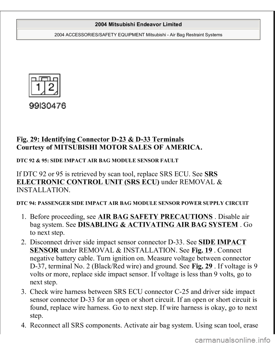
Fig. 29: Identifying Connector D
-23 & D
-33 Terminals
Courtesy of MITSUBISHI MOTOR SALES OF AMERICA.
DTC 92 & 95: SIDE IMPACT AIR BAG MODULE SENSOR FAULT If DTC 92 or 95 is retrieved by scan tool, replace SRS ECU. See SRS ELECTRONIC CONTROL UNIT (SRS ECU)
under REMOVAL &
INSTALLATION.
DTC 94: PASSENGER SIDE IMPACT AIR BAG MODULE SENSOR POWER SUPPLY CIRCUIT 1. Before proceeding, see AIR BAG SAFETY PRECAUTIONS
. Disable air
bag system. See DISABLING & ACTIVATING AIR BAG SYSTEM
. Go
to next step.
2. Disconnect driver side impact sensor connector D-33. See SIDE IMPACT
SENSOR
under REMOVAL & INSTALLATION. See Fig. 19
. Connect
negative battery cable. Turn ignition on. Measure voltage between connector
D-37, terminal No. 2 (Black/Red wire) and ground. See Fig. 29 . If voltage is 9
volts or more, replace side impact sensor. If voltage is less than 9 volts, go to
next step.
3. Check wire harness between SRS ECU connector C-25 and driver side impact
sensor connector D-33 for an open or short circuit. If an open or short circuit is
found, replace wire harness. Go to next step. If wire harness is okay, go to next
step.
4. Reconnect all SRS com
ponents. Activate air ba
g system. Usin
g scan tool, erase
2004 Mitsubishi Endeavor Limited
2004 ACCESSORIES/SAFETY EQUIPMENT Mitsubishi - Air Bag Restraint Systems