2004 MITSUBISHI ENDEAVOR ignition
[x] Cancel search: ignitionPage 300 of 3870
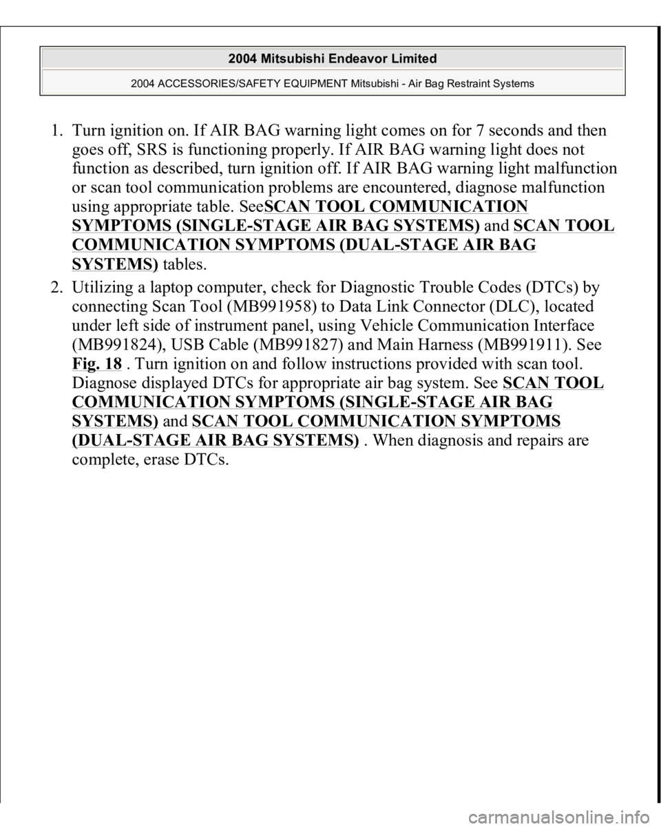
1. Turn ignition on. If AIR BAG warning light comes on for 7 seconds and then
goes off, SRS is functioning properly. If AIR BAG warning light does not
function as described, turn ignition off. If AIR BAG warning light malfunction
or scan tool communication problems are encountered, diagnose malfunction
using appropriate table. SeeSCAN TOOL COMMUNICATION
SYMPTOMS (SINGLE
-STAGE AIR BAG SYSTEMS)
and SCAN TOOL
COMMUNICATION SYMPTOMS (DUAL
-STAGE AIR BAG
SYSTEMS)
tables.
2. Utilizing a laptop computer, check for Diagnostic Trouble Codes (DTCs) by
connecting Scan Tool (MB991958) to Data Link Connector (DLC), located
under left side of instrument panel, using Vehicle Communication Interface
(MB991824), USB Cable (MB991827) and Main Harness (MB991911). See
Fig. 18
. Turn ignition on and follow instructions provided with scan tool.
Diagnose displayed DTCs for appropriate air bag system. See SCAN TOOL
COMMUNICATION SYMPTOMS (SINGLE
-STAGE AIR BAG
SYSTEMS)
and SCAN TOOL COMMUNICATION SYMPTOMS
(DUAL
-STAGE AIR BAG SYSTEMS)
. When diagnosis and repairs are
com
plete, erase DTCs.
2004 Mitsubishi Endeavor Limited
2004 ACCESSORIES/SAFETY EQUIPMENT Mitsubishi - Air Bag Restraint Systems
Page 302 of 3870
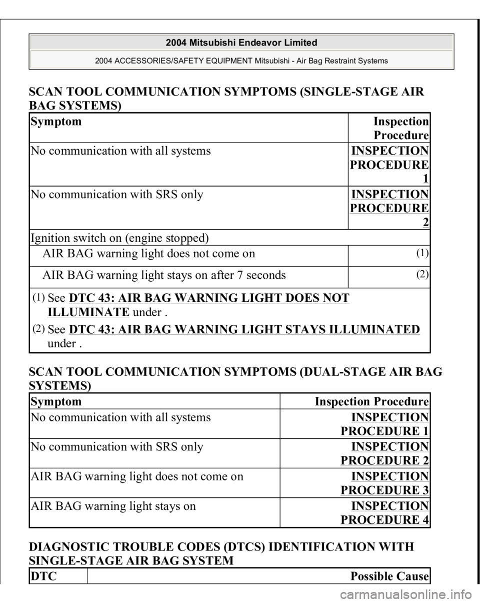
SCAN TOOL COMMUNICATION SYMPTOMS (SINGLE-STAGE AI
R
BAG SYSTEMS)
SCAN TOOL COMMUNICATION SYMPTOMS (DUAL-STAGE AIR BAG
SYSTEMS)
DIAGNOSTIC TROUBLE CODES (DTCS) IDENTIFICATION WITH
SINGLE-STAGE AIR BAG SYSTEM
Symptom
Ins
pection
Procedure
No communication with all systems
INSPECTION PROCEDURE
1
No communication with SRS only
INSPECTION PROCEDURE
2
Ignition switch on (engine stopped)AIR BAG warning light does not come on
(1)
AIR BAG warning light stays on after 7 seconds
(2)
(1)
See DTC 43: AIR BAG WARNING LIGHT DOES NOT ILLUMINATE
under .
(2)
See DTC 43: AIR BAG WARNING LIGHT STAYS ILLUMINATED
under .
Symptom
Inspection Procedure
No communication with all systems
INSPECTION PROCEDURE 1
No communication with SRS only
INSPECTION PROCEDURE 2
AIR BAG warning light does not come on
INSPECTION PROCEDURE 3
AIR BAG warning light stays on
INSPECTION PROCEDURE 4
DTC
Possible Cause
2004 Mitsubishi Endeavor Limited
2004 ACCESSORIES/SAFETY EQUIPMENT Mitsubishi - Air Bag Restraint Systems
Page 306 of 3870
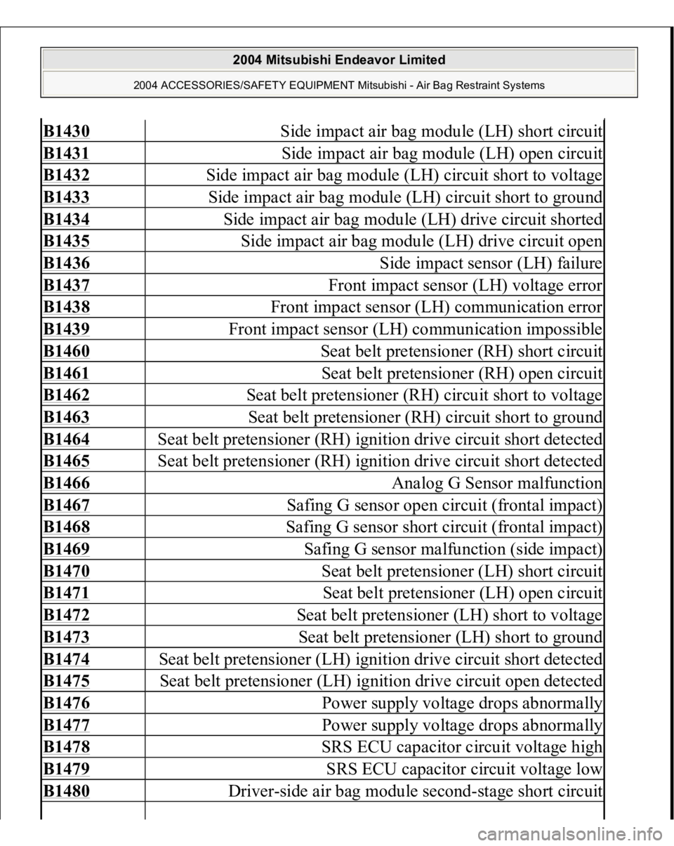
B1430
Side impact air bag module (LH) short circuit
B1431
Side impact air bag module (LH) open circuit
B1432
Side impact air bag module (LH) circuit short to voltage
B1433
Side impact air bag module (LH) circuit short to ground
B1434
Side impact air bag module (LH) drive circuit shorted
B1435
Side impact air bag module (LH) drive circuit open
B1436
Side impact sensor (LH) failure
B1437
Front impact sensor (LH) voltage error
B1438
Front impact sensor (LH) communication error
B1439
Front impact sensor (LH) communication impossible
B1460
Seat belt pretensioner (RH) short circuit
B1461
Seat belt pretensioner (RH) open circuit
B1462
Seat belt pretensioner (RH) circuit short to voltage
B1463
Seat belt pretensioner (RH) circuit short to ground
B1464
Seat belt pretensioner (RH) ignition drive circuit short detected
B1465
Seat belt pretensioner (RH) ignition drive circuit short detected
B1466
Analog G Sensor malfunction
B1467
Safing G sensor open circuit (frontal impact)
B1468
Safing G sensor short circuit (frontal impact)
B1469
Safing G sensor malfunction (side impact)
B1470
Seat belt pretensioner (LH) short circuit
B1471
Seat belt pretensioner (LH) open circuit
B1472
Seat belt pretensioner (LH) short to voltage
B1473
Seat belt pretensioner (LH) short to ground
B1474
Seat belt pretensioner (LH) ignition drive circuit short detected
B1475
Seat belt pretensioner (LH) ignition drive circuit open detected
B1476
Power supply voltage drops abnormally
B1477
Power supply voltage drops abnormally
B1478
SRS ECU capacitor circuit voltage high
B1479
SRS ECU capacitor circuit voltage low
B1480
Driver-side air bag module second-stage short circuit
2004 Mitsubishi Endeavor Limited
2004 ACCESSORIES/SAFETY EQUIPMENT Mitsubishi - Air Bag Restraint Systems
Page 309 of 3870
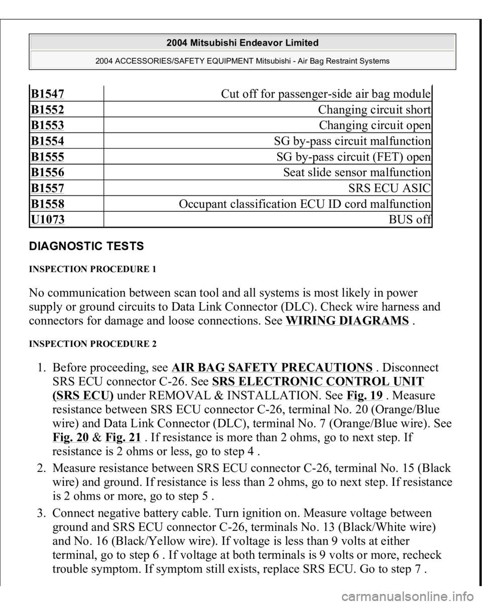
DIAGNOSTIC TESTS INSPECTION PROCEDURE 1 No communication between scan tool and all systems is most likely in power
supply or ground circuits to Data Link Connector (DLC). Check wire harness and
connectors for damage and loose connections. See WIRING DIAGRAMS
.
INSPECTION PROCEDURE 2 1. Before proceeding, see AIR BAG SAFETY PRECAUTIONS
. Disconnect
SRS ECU connector C-26. See SRS ELECTRONIC CONTROL UNIT
(SRS ECU)
under REMOVAL & INSTALLATION. See Fig. 19
. Measure
resistance between SRS ECU connector C-26, terminal No. 20 (Orange/Blue
wire) and Data Link Connector (DLC), terminal No. 7 (Orange/Blue wire). See
Fig. 20
& Fig. 21
. If resistance is more than 2 ohms, go to next step. If
resistance is 2 ohms or less, go to step 4 .
2. Measure resistance between SRS ECU connector C-26, terminal No. 15 (Black
wire) and ground. If resistance is less than 2 ohms, go to next step. If resistance
is 2 ohms or more, go to step 5 .
3. Connect negative battery cable. Turn ignition on. Measure voltage between
ground and SRS ECU connector C-26, terminals No. 13 (Black/White wire)
and No. 16 (Black/Yellow wire). If voltage is less than 9 volts at either
terminal, go to step 6 . If voltage at both terminals is 9 volts or more, recheck
trouble s
ymptom. If s
ymptom still exists, re
place SRS ECU. Go to ste
p 7 .
B1547
Cut off for passenger-side air bag module
B1552
Changing circuit short
B1553
Changing circuit open
B1554
SG by-pass circuit malfunction
B1555
SG by-pass circuit (FET) open
B1556
Seat slide sensor malfunction
B1557
SRS ECU ASIC
B1558
Occupant classification ECU ID cord malfunction
U1073
BUS of
f
2004 Mitsubishi Endeavor Limited
2004 ACCESSORIES/SAFETY EQUIPMENT Mitsubishi - Air Bag Restraint Systems
Page 310 of 3870
4. Inspect wire harness between SRS ECU connector C-26, terminal No. 20
(Orange/Blue wire) and Data Link Connector C-23, terminal No. 7
(Orange/Blue wire), including connector C-104, for damage, loose connectors
or poor connections. If wire harness is okay, go to step 7 . If wire harness is not
okay, replace wire harness. Go to step 7 .
5. Inspect wire harness between SRS ECU connector C-26, terminals No. 15
(Black wire) and ground. If wire harness is okay, go to step 7 . If wire harness
is not okay, replace wire harness. Go to step 7 .
6. Inspect wire harness between SRS ECU connector C-26, terminals No. 13
(Black/White wire) and No. 16 (Black/Yellow wire) and ignition switch
connector C-308, including connectors C-211 and C-215. See Fig. 22
. If wire
harness is okay, go to next step. If wire harness is not okay, replace wire
harness. Go to step 7 .
7. Connect all SRS connectors. If scan tool communicates normally with SRS,
repair is complete. If communication is not normal, intermittent condition may
exist.
2004 Mitsubishi Endeavor Limited
2004 ACCESSORIES/SAFETY EQUIPMENT Mitsubishi - Air Bag Restraint Systems
Page 326 of 3870
3. Reconnect all SRS components. Using scan tool, erase then retrieve DTCs. If
DTC 34 is retrieved, go to step 1 . If DTC 34 is not retrieved, system is normal
at this time. Intermittent condition may exist. DTC 35: SRS ECU AIR BAG DEPLOYMENT If DTC 35 is present, replace SRS ECU. See SRS ELECTRONIC CONTROL UNIT (SRS ECU)
under REMOVAL & INSTALLATION.
DTC 41: IG1 POWER CIRCUIT 1. Before proceeding, see AIR BAG SAFETY PRECAUTIONS
. Disable air
bag system. See DISABLING & ACTIVATING AIR BAG SYSTEM
.
Inspect fuse No. 23 in driver-side junction block, located on left side of
instrument panel. If fuse is okay, go to next step. If fuse is not okay, go to step
4 .
2. Disconnect negative battery cable. Disconnect SRS ECU connector C-26. See
SRS ELECTRONIC CONTROL UNIT (SRS ECU)
under REMOVAL &
INSTALLATION. See Fig. 19
. Connect negative battery cable. Turn ignition
on. Measure voltage between ground and SRS ECU connector C-26, terminal
No. 16 (Black/Yellow wire). See Fig. 21
. If voltage is less than 9 volts, go to
next step. If voltage is 9 volts or more, erase then retrieve DTCs using scan
tool. If DTC 41 is retrieved, replace SRS ECU. Go to step 10 .
3. Check wire harness between SRS ECU connector C-26, terminal No. 16 and
ignition switch connector C-308, terminal No. 2, including connectors C-211
and C-215. See Fig. 22
. If wire harness or connectors are damaged, replace
wire harness. Go to step 10 . If wire harness and connectors are okay, go to
step 10 .
4. Replace fuse. Turn ignition on for at least one minute, then off. Inspect fuse. If
fuse is okay, go to step 10 . If fuse is not okay, go to next step.
5. Disconnect connector C-211 from junction block. Check for continuity
between ground and connector C-211, terminal No. 24 (Black/Yellow wire).
See Fig. 26
. If continuity exists, go to next step. If continuity does not exist,
go to step 8 .
6. Check for continuity between ground and terminal No. 25 (Black/White wire)
of connector C-211. If continuit
y does not exist
, check other circuits associated
2004 Mitsubishi Endeavor Limited
2004 ACCESSORIES/SAFETY EQUIPMENT Mitsubishi - Air Bag Restraint Systems
Page 328 of 3870
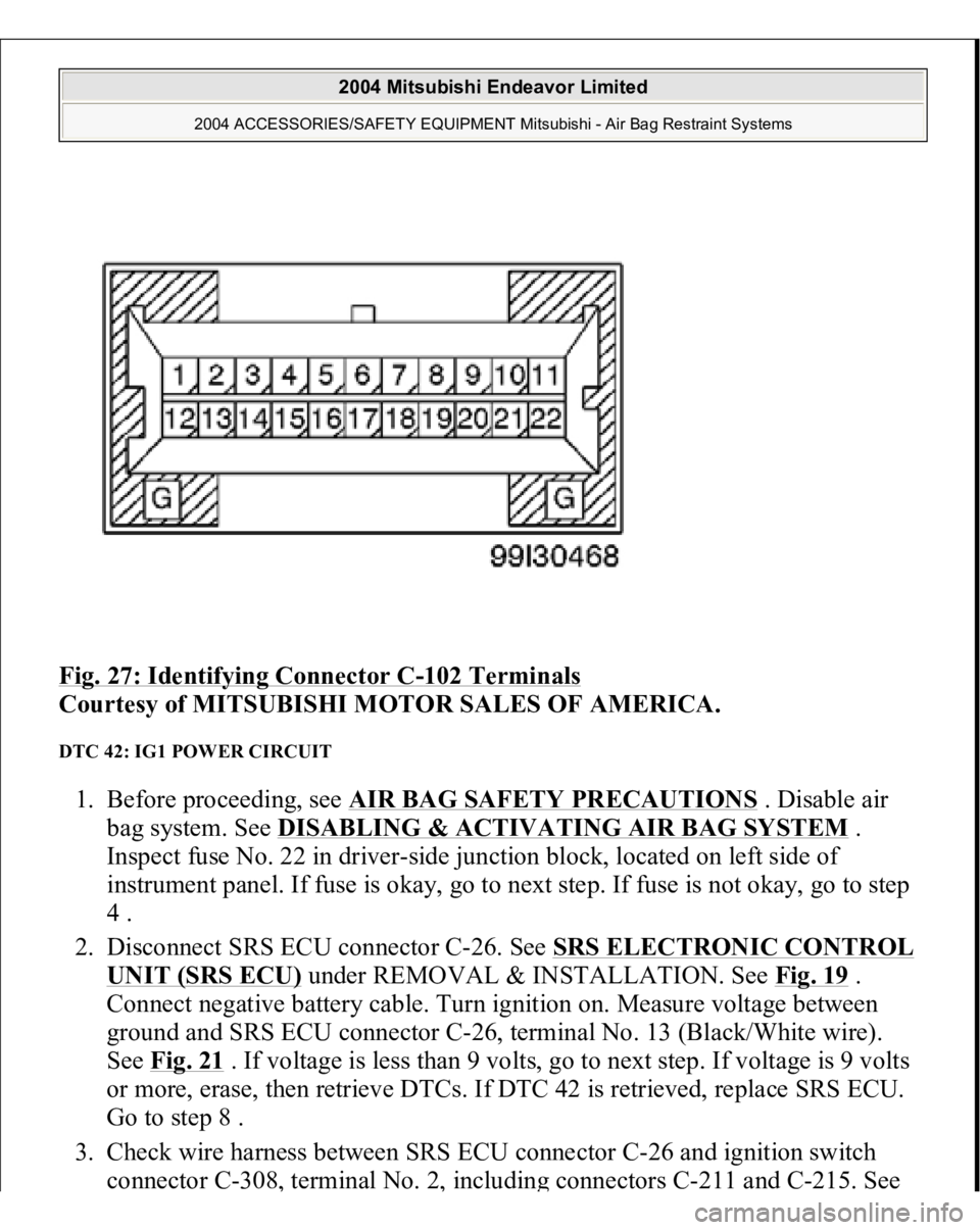
Fig. 27: Identifying Connector C
-102 Terminals
Courtesy of MITSUBISHI MOTOR SALES OF AMERICA.
DTC 42: IG1 POWER CIRCUIT 1. Before proceeding, see AIR BAG SAFETY PRECAUTIONS
. Disable air
bag system. See DISABLING & ACTIVATING AIR BAG SYSTEM
.
Inspect fuse No. 22 in driver-side junction block, located on left side of
instrument panel. If fuse is okay, go to next step. If fuse is not okay, go to step
4 .
2. Disconnect SRS ECU connector C-26. See SRS ELECTRONIC CONTROL
UNIT (SRS ECU)
under REMOVAL & INSTALLATION. See Fig. 19
.
Connect negative battery cable. Turn ignition on. Measure voltage between
ground and SRS ECU connector C-26, terminal No. 13 (Black/White wire).
See Fig. 21
. If voltage is less than 9 volts, go to next step. If voltage is 9 volts
or more, erase, then retrieve DTCs. If DTC 42 is retrieved, replace SRS ECU.
Go to step 8 .
3. Check wire harness between SRS ECU connector C-26 and ignition switch
connector C-308
, terminal No. 2
, includin
g connectors C-211 and C-215. See
2004 Mitsubishi Endeavor Limited
2004 ACCESSORIES/SAFETY EQUIPMENT Mitsubishi - Air Bag Restraint Systems
Page 329 of 3870
Fig. 22
. If wire harness and connectors are damaged, replace wire harness. Go
to step 8 . If wire harness and connectors are okay, go to step 8 .
4. Replace fuse. Turn ignition on for at least one minute, then off. Inspect fuse. If
fuse is okay, go to step 8 . If fuse is not okay, go to next step.
5. Disconnect connector C-211 from junction block. Check for continuity
between ground and terminal No. 7 (Yellow/Black wire) of connector C-211. I
f
continuity exists, check all circuits associated with fuse No. 3 for a short to
ground. If continuity does not exist, go to next step.
6. Disconnect SRS ECU connector C-26. Check for continuity between SRS ECU
connector C-26, terminal No. 13 (Black/White wire) and ground. If continuity
exists, go to next step. If continuity does not exist, erase, then retrieve DTCs
using scan tool. If DTC 42 is retrieved, replace SRS ECU. Go to step 8 .
7. Check Black/White wire between SRS ECU connector C-26, terminal No. 13
and junction block connector C-205, terminal No. 7 for an open, short or
damage. If wire is okay, go to next step. If wire is not okay, replace wire
harness and go to next step.
8. Reconnect all SRS components. Activate air bag system. Using scan tool, erase
then retrieve DTCs. If DTC 42 is retrieved, go to step 1 . If DTC 42 is not
retrieved, system is normal at this time. Intermittent condition may exist.
DTC 43: AIR BAG WARNING LIGHT DOES NOT ILLUMINATE 1. Before proceeding, see AIR BAG SAFETY PRECAUTIONS
. Disable air
bag system. See DISABLING & ACTIVATING AIR BAG SYSTEM
.
Disconnect SRS ECU connector C-26. See SRS ELECTRONIC CONTROL
UNIT (SRS ECU)
under REMOVAL & INSTALLATION. See Fig. 19
.
Connect negative battery cable. Turn ignition on. If AIR BAG warning light
does not illuminate, go to next step. If AIR BAG warning light illuminates, go
to step 3 .
2. Inspect wire harness between ignition switch connector C-308 and SRS ECU
connector C-26 and between C-26 and combination meter connector C-102 for
damage, a short or open circuit. If wire harness is okay, replace combination
meter assembly. Go to next step. If wire harness is not okay, replace wire
harness. Go to next step.
3. Reconnect all SRS com
ponents. Activate air ba
g system. Usin
g scan tool, erase
2004 Mitsubishi Endeavor Limited
2004 ACCESSORIES/SAFETY EQUIPMENT Mitsubishi - Air Bag Restraint Systems