Page 3205 of 3870

DTC C1211 is set: Rear right ABS sensor DTC C1216 is set: Rear left ABS sensor
Q: Is the ABS rotor in good condition?
YES: Go to Step 8.
NO (front bearing end play is not within the standard value): If the
ABS rotor is contaminated with foreign material, clean it. If the driveshaft
is deformed, replace it (Refer to DRIVE SHAFT ASSEMBLY
, ). Then
go to Step 16.
NO (rear bearing end play is not within the standard value): If the
ABS rotor is contaminated with foreign material, clean it. If the BJ
assembly is deformed, replace it (Refer to DRIVE SHAFT
ASSEMBLY
). Then go to Step 16.
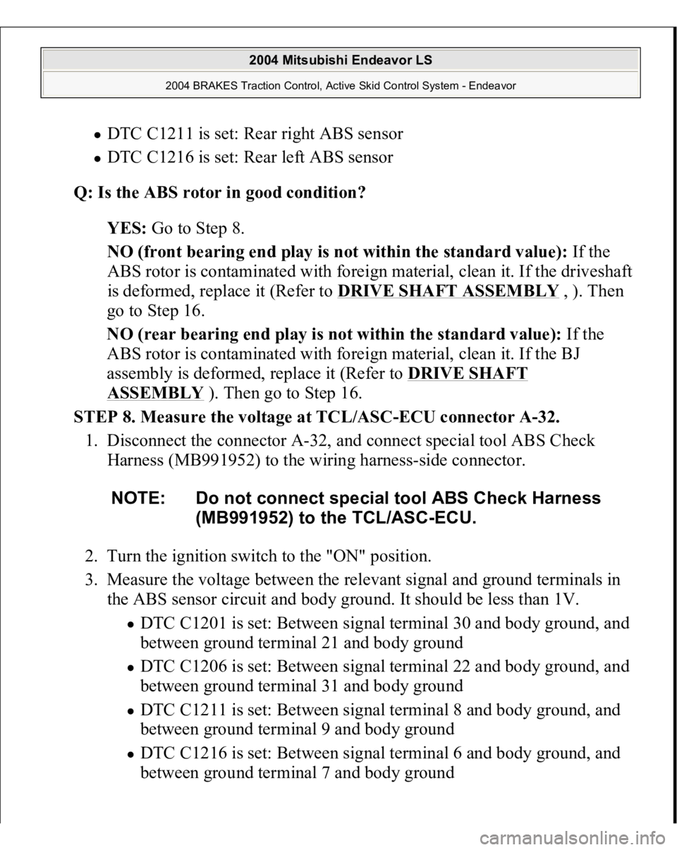
STEP 8. Measure the voltage at TCL/ASC-ECU connector A-32.
1. Disconnect the connector A-32, and connect special tool ABS Check
Harness (MB991952) to the wiring harness-side connector.
2. Turn the ignition switch to the "ON" position.
3. Measure the voltage between the relevant signal and ground terminals in
the ABS sensor circuit and body ground. It should be less than 1V.
DTC C1201 is set: Between signal terminal 30 and body ground, and
between ground terminal 21 and body ground DTC C1206 is set: Between signal terminal 22 and body ground, and
between ground terminal 31 and body ground DTC C1211 is set: Between signal terminal 8 and body ground, and
between ground terminal 9 and body ground DTC C1216 is set: Between signal terminal 6 and body ground, and between
ground terminal 7 and bod
y ground
NOTE: Do not connect special tool ABS Check Harness
(MB991952) to the TCL/ASC-ECU.
2004 Mitsubishi Endeavor LS
2004 BRAKES Traction Control, Active Skid Control System - Endeavor
Page 3206 of 3870
Fig. 73: Measuring Voltage At TCL/ASC
-ECU Connector A
-32
Courtesy of MITSUBISHI MOTOR SALES OF AMERICA.
2004 Mitsubishi Endeavor LS
2004 BRAKES Traction Control, Active Skid Control System - Endeavor
Page 3207 of 3870

Q: Does the voltage measure 1 V or less?
YES: Go to Step 9.
NO (When the voltage between terminal 30 or 21 - and body ground
measures more than 1 V): Go to Step 11.
NO (When the voltage between terminal 22 or 31 - and body ground
measures more than 1 V): Go to Step 12.
NO (When the voltage between terminal 8 or 9 - and body ground
measures more than 1 V): Go to Step 13.
NO (When the voltage between terminal 6 or 7 - and body ground
measures more than 1 V): Go to Step 14.
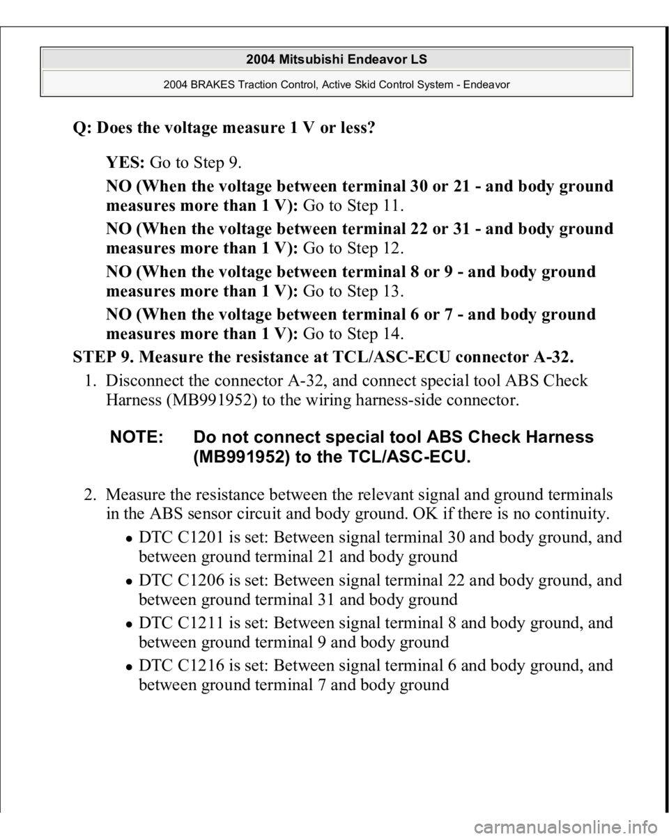
STEP 9. Measure the resistance at TCL/ASC-ECU connector A-32.
1. Disconnect the connector A-32, and connect special tool ABS Check
Harness (MB991952) to the wiring harness-side connector.
2. Measure the resistance between the relevant signal and ground terminals
in the ABS sensor circuit and body ground. OK if there is no continuity.
DTC C1201 is set: Between signal terminal 30 and body ground, and
between ground terminal 21 and body ground DTC C1206 is set: Between signal terminal 22 and body ground, and
between ground terminal 31 and body ground DTC C1211 is set: Between signal terminal 8 and body ground, and
between ground terminal 9 and body ground DTC C1216 is set: Between signal terminal 6 and body ground, and between ground terminal 7 and body ground
NOTE: Do not connect special tool ABS Check Harness
(MB991952) to the TCL/ASC-ECU.
2004 Mitsubishi Endeavor LS
2004 BRAKES Traction Control, Active Skid Control System - Endeavor
Page 3208 of 3870
Fig. 74: Measuring Voltage At TCL/ASC
-ECU Connector A
-32
Courtesy of MITSUBISHI MOTOR SALES OF AMERICA.
2004 Mitsubishi Endeavor LS
2004 BRAKES Traction Control, Active Skid Control System - Endeavor
Page 3209 of 3870

Q: Does continuity exist?
YES (Continuity exists between terminal 30 or terminal 21 and body
ground): Go to Step 11.
YES (Continuity exists between terminal 22 or terminal 31 and body
ground): Go to Step 12.
YES (Continuity exists between terminal 8 or terminal 9 and body
ground): Go to Step 13.
YES (Continuity exists between terminal 6 or terminal 7 and body
ground): Go to Step 14.
NO: Go to Step 10.
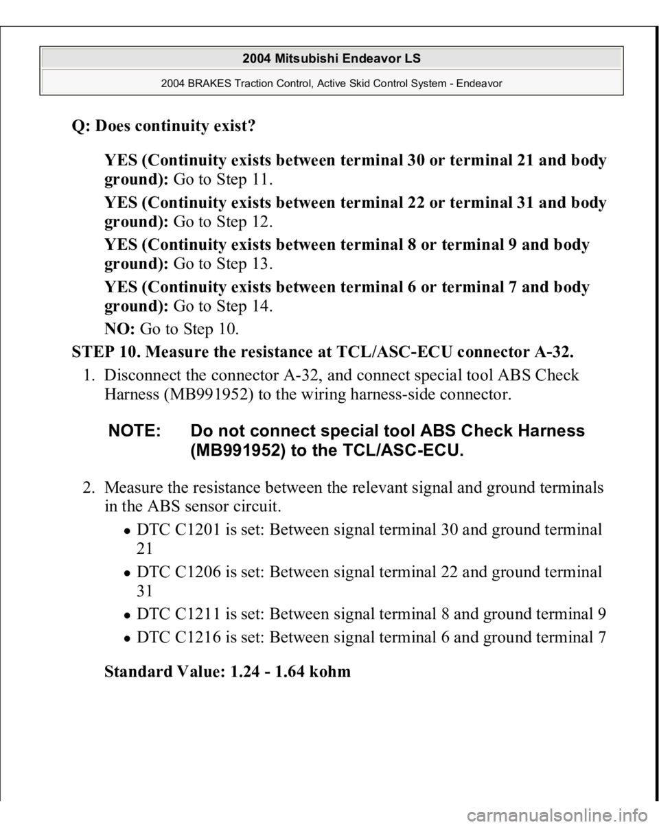
STEP 10. Measure the resistance at TCL/ASC-ECU connector A-32.
1. Disconnect the connector A-32, and connect special tool ABS Check
Harness (MB991952) to the wiring harness-side connector.
2. Measure the resistance between the relevant signal and ground terminals
in the ABS sensor circuit.
DTC C1201 is set: Between signal terminal 30 and ground terminal
21 DTC C1206 is set: Between signal terminal 22 and ground terminal
31 DTC C1211 is set: Between signal terminal 8 and ground terminal 9 DTC C1216 is set: Between signal terminal 6 and ground terminal 7
Standard Value: 1.24 - 1.64 kohm
NOTE: Do not connect special tool ABS Check Harness
(MB991952) to the TCL/ASC-ECU.
2004 Mitsubishi Endeavor LS
2004 BRAKES Traction Control, Active Skid Control System - Endeavor
Page 3210 of 3870
Fig. 75: Measuring Voltage At TCL/ASC
-ECU Connector A
-32 (Step
10)
Courtesy of MITSUBISHI MOTOR SALES OF AMERICA.
2004 Mitsubishi Endeavor LS
2004 BRAKES Traction Control, Active Skid Control System - Endeavor
Page 3211 of 3870
Q: Is the resistance between terminals 30 and 21, 22 and 31, 8 and 9, or 6
and 7 within the standard value?
YES (When resistances between all terminals are within the standard
value): Go to Step 15.
NO (When resistance between terminals 30 and 21 is not within the
standard value): Go to Step 11.
NO (When resistance between terminals 22 and 31 is not within the
standard value): Go to Step 12.
NO (When resistance between terminals 8 and 9 is not within the
standard value): Go to Step 13.
NO (When resistance between terminals 6 and 7 is not within the
standard value): Go to Step 14.
STEP 11. Check TCL/ASC-ECU connector A-32 and ABS sensor < front:
RH > connector A-31 for loose, corroded or damaged terminals, or
terminals pushed back in the connector.
2004 Mitsubishi Endeavor LS
2004 BRAKES Traction Control, Active Skid Control System - Endeavor
Page 3212 of 3870
Fig. 76: Checking TCL/ASC
-ECU Connector A
-32
Courtesy of MITSUBISHI MOTOR SALES OF AMERICA.
2004 Mitsubishi Endeavor LS
2004 BRAKES Traction Control, Active Skid Control System - Endeavor