Page 3215 of 3870
Fig. 79: Checking ABS Sensor Connector A
-14
Courtesy of MITSUBISHI MOTOR SALES OF AMERICA.
Q: Are TCL/ASC-ECU connector A-32 and ABS sensor < front: LH >
connector A-14 damaged?
YES: Repair or replace the damaged component(s). Then go to Step 16.
NO: Open or short circuit may be present in the front right ABS sensor
circuit. Repair the wiring harness between TCL/ASC-ECU connector A-
32 (terminals 22 and 31) and front left ABS sensor A-14 (terminals 2 and
1). Then go to Step 16.
STEP 13. Check TCL/ASC-ECU connector A-32, intermediate connector
C-32 and ABS sensor < rear: RH > connector D-10 for loose, corroded or
damaged terminals, or terminals pushed back in the connector.
2004 Mitsubishi Endeavor LS
2004 BRAKES Traction Control, Active Skid Control System - Endeavor
Page 3218 of 3870
Fig. 82: Checking ABS Sensor Connector D
-10 (Step 13)
Courtesy of MITSUBISHI MOTOR SALES OF AMERICA.
Q: Are TCL/ASC-ECU connector A-32, intermediate connector C-32 and
ABS sensor < rear: RH > connector D-10 damaged?
YES: Repair or replace the damaged component(s). Then go to Step 16.
NO: Open or short circuit may be present in the rear right ABS sensor
circuit. Repair the wiring harness between TCL/ASC-ECU connector A-
32 (terminals 8 and 9) and rear right ABS sensor D-10 (terminals 1 and 2).
Then go to Step 16
.
STEP 14. Check TCL/ASC-ECU connector A-32, intermediate connector
C-32 and ABS sensor < rear: LH > connector D-15 for loose, corroded or
damaged terminals, or terminals pushed back in the connector.
2004 Mitsubishi Endeavor LS
2004 BRAKES Traction Control, Active Skid Control System - Endeavor
Page 3221 of 3870
Fig. 85: Checking ABS Sensor Connector D
-15 (Step 14)
Courtesy of MITSUBISHI MOTOR SALES OF AMERICA.
Q: Are TCL/ASC-ECU connector A-32, intermediate connector C-32 and
ABS sensor < rear: LH > connector D-15 damaged?
YES: Repair or replace the damaged component(s). Then go to Step 16.
NO: Open or short circuit may be present in the rear left ABS sensor
circuit. Repair the wiring harness between TCL/ASC-ECU connector A-
32 (terminals 6 and 7) and rear left ABS sensor D-10 (terminals 1 and 2).
Then go to Step 16
.
STEP 15. Recheck for diagnostic trouble code.
Check again if the DTC is set.
1. Turn the ignition switch to the "ON" position.
2004 Mitsubishi Endeavor LS
2004 BRAKES Traction Control, Active Skid Control System - Endeavor
Page 3419 of 3870
2. Turn the ignition switch to "ON" position.
3. Diagnose the CAN bus line.
Q: Is the check result satisfactory?
YES: Go to Step 2
NO: Repair the CAN bus lines (Refer to DIAGNOSTIC TROUBLE
CODE DIAGNOSIS
or DIAGNOSIS < VEHICLES WITHOUT
ADVANCED AIR BAG
). On completion, go to Step 6.
STEP 2. Using scan tool MB991958, read the steering wheel sensor
diagnostic trouble code.
Check if a steering wheel sensor DTC is set.
Q: Is the DTC set?
YES: Diagnose the steering wheel sensor by referring to DIAGNOSTIC
TROUBLE CODE CHART
.
NO: Go to Step 3.
STEP 3. Using scan tool MB991958 read any of the diagnostic trouble
code.
Check if a DTC, which relates to CAN communication-linked systems below,
is set.
Power train control module
DTC U1100: ABS-ECU time-out
Combination meter DTC 011: ABS-ECU time-out
Q: Is the DTC set?
YES: Go to Step 4. NO:
Go to Step
5.
2004 Mitsubishi Endeavor LS
2004 BRAKES Traction Control, Active Skid Control System - Endeavor
Page 3425 of 3870

Courtesy of MITSUBISHI MOTOR SALES OF AMERICA
.
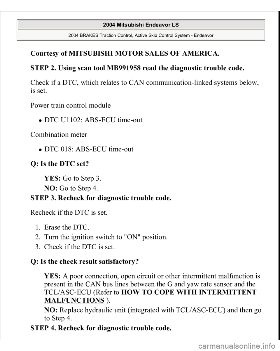
STEP 2. Using scan tool MB991958 read the diagnostic trouble code.
Check if a DTC, which relates to CAN communication-linked systems below,
is set.
Power train control module
DTC U1102: ABS-ECU time-out
Combination meter DTC 018: ABS-ECU time-out
Q: Is the DTC set?
YES: Go to Step 3.
NO: Go to Step 4.
STEP 3. Recheck for diagnostic trouble code.
Recheck if the DTC is set.
1. Erase the DTC.
2. Turn the ignition switch to "ON" position.
3. Check if the DTC is set.
Q: Is the check result satisfactory?
YES: A poor connection, open circuit or other intermittent malfunction is
present in the CAN bus lines between the G and yaw rate sensor and the
TCL/ASC-ECU (Refer to HOW TO COPE WITH INTERMITTENT MALFUNCTIONS
).
NO: Replace hydraulic unit (integrated with TCL/ASC-ECU) and then go
to Step 4.
STEP 4. Recheck for diagnostic trouble code.
2004 Mitsubishi Endeavor LS
2004 BRAKES Traction Control, Active Skid Control System - Endeavor
Page 3473 of 3870
Fig. 213: Identifying Connectors: C
-211, C
-215, C
-312
Courtesy of MITSUBISHI MOTOR SALES OF AMERICA.
CIRCUIT OPERATION
The steering wheel sensor is energized by the ignition switch (IG2) through
multi-purpose fuse 13 and the steering wheel sensor terminal 2. If the power supply to the steering wheel sensor has failed, scan tool (MUT-III
Sub Assembly) will not be able to communicate with it.
TROUBLESHOOTING HINTS (The most likely causes for this case:)
Damaged wiring harness or connector Defective battery Charging system failed Malfunction of the steering wheel sensor
DIAGNOSIS Required Special Tools:
MB991958: Scan Tool (MUT-III Sub Assembly)
MB991824: Vehicle Communication Interface (V.C.I.) MB991827: MUT-III USB Cable MB991910: MUT-III Main Harness A
MB991952: ABS Check Harness
STEP 1. Measure the volta
ge at steerin
g wheel sensor connector C-312
.
2004 Mitsubishi Endeavor LS
2004 BRAKES Traction Control, Active Skid Control System - Endeavor
Page 3486 of 3870
Malfunction of the G and yaw rate sensor
DIAGNOSIS Required Special Tools:
MB991958: Scan Tool (MUT-III Sub Assembly)
MB991824: Vehicle Communication Interface (V.C.I.) MB991827: MUT-III USB Cable MB991910: MUT-III Main Harness A
MB991952: ABS Check Harness
STEP 1. Measure the voltage at G and yaw rate sensor connector C-36.
1. Disconnect the G and yaw rate sensor connector C-36, and measure at the
harness side connector.
2. Turn the ignition switch to the "ON" position.
3. Measure the voltage between terminal 1 and body ground.
Voltage should measure battery positive voltage (approximately 12
volts
).
2004 Mitsubishi Endeavor LS
2004 BRAKES Traction Control, Active Skid Control System - Endeavor
Page 3694 of 3870

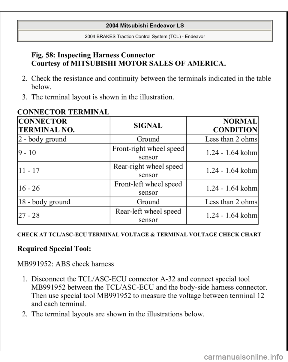
Fig. 58: Inspecting Harness Connector
Courtesy of MITSUBISHI MOTOR SALES OF AMERICA.
2. Check the resistance and continuity between the terminals indicated in the table
below.
3. The terminal layout is shown in the illustration.
CONNECTOR TERMINAL
CHECK AT TCL/ASC-ECU TERMINAL VOLTAGE & TERMINAL VOLTAGE CHECK CHART Required Special Tool:
MB991952: ABS check harness
1. Disconnect the TCL/ASC-ECU connector A-32 and connect special tool
MB991952 between the TCL/ASC-ECU and the body-side harness connector.
Then use special tool MB991952 to measure the voltage between terminal 12
and each terminal.
2. The terminal la
youts are shown in the illustrations below.
CONNECTOR
TERMINAL NO.
SIGNAL
NORMAL
CONDITION
2 - body ground
Ground
Less than 2 ohms
9 - 10
Front-right wheel speed
sensor
1.24 - 1.64 kohm
11 - 17
Rear-right wheel speed
sensor
1.24 - 1.64 kohm
16 - 26
Front-left wheel speed
sensor
1.24 - 1.64 kohm
18 - body ground
Ground
Less than 2 ohms
27 - 28
Rear-left wheel speed
sensor
1.24 - 1.64 kohm
2004 Mitsubishi Endeavor LS
2004 BRAKES Traction Control System (TCL) - Endeavor