Page 411 of 3870
shorting bar using a cable tie. Measure voltage between ground and SRS ECU
connector terminals No. 31 (Yellow/Pink wire) and No. 30 (Yellow/Gray
wire). See Fig. 33
. If voltage is measured at either terminal, go to next step. If
voltage is not measured at either terminal, reconnect SRS components. Erase,
then retrieve DTCs. If DTC B1492 is retrieved, replace SRS ECU. Go to step
6 .
5. Replace wire harness between SRS ECU and passenger-side air bag module.
Go to next step.
6. Reconnect all SRS components. Activate air bag system. Using scan tool,
retrieve DTCs. If DTC B1492 is retrieved, go to step 1 . If DTC B1492 is not
retrieved, system is normal at this time.
DTC B1493: PASSENGER-SIDE AIR BAG MODULE SECOND-STAGE SHORT TO GROUND 1. Connect scan tool to Data Link Connector (DLC). See INITIAL SRS
DIAGNOSTIC PROCEDURE
under DIAGNOSTICS. If scan tool is able to
diagnose CAN bus lines and CAN bus lines are satisfactory, go to next step. If
scan tool cannot diagnose CAN bus lines, repair CAN bus lines. Go to next
step.
2. Erase, then retrieve DTCs. Turn ignition off. If DTC B1493 is retrieved, go to
next step. If DTC B1493 is not retrieved, an intermittent condition may exist.
3. Disconnect negative battery cable. Disconnect passenger-side air bag module
connector C-09. See PASSENGER
-SIDE AIR BAG MODULE
under
REMOVAL & INSTALLATION. See Fig. 30
. Connect Load Resistor
(MB991865) to Load Resistor Adapter (MB991866). Insert load resistor
adapter leads into harness-side terminals No. 3 (Yellow/Pink wire) and No. 4
(Yellow/Gray wire) of connector C-09. See Fig. 35
. Connect negative battery
cable. Erase, then retrieve DTCs. If DTC B1493 is retrieved, go to next step. If
DTC B1493 is not retrieved, replace passenger-side air bag module. Go to step
6 .
4. Disconnect negative battery cable. Remove load resistor and load resistor
adapter from passenger-side air bag module connector C-09. Disconnect SRS
ECU connector C-26. See SRS ELECTRONIC CONTROL UNIT (SRS
ECU)
under REMOVAL & INSTALLATION. Release SRS ECU connector
shorting bar usin
g a cable tie. Measure resistance
between
ground and SRS
2004 Mitsubishi Endeavor Limited
2004 ACCESSORIES/SAFETY EQUIPMENT Mitsubishi - Air Bag Restraint Systems
Page 412 of 3870
ECU connector terminals No. 31 (Yellow/Pink wire) and No. 30 (Yellow/Gray
wire). If resistance is not infinite at both terminals, go to next step. If resistance
is infinite at both terminals, reconnect SRS components. Erase, then retrieve
DTCs. If DTC B1493 is retrieved, replace SRS ECU. Go to step 6 .
5. Replace wire harness between SRS ECU and passenger-side air bag module.
Go to next step.
6. Reconnect all SRS components. Activate air bag system. Using scan tool,
retrieve DTCs. If DTC B1493 is retrieved, go to step 1 . If DTC B1493 is not
retrieved, system is normal at this time.
DTC B1494: PASSENGER-SIDE AIR BAG MODULE SECOND-STAGE ACTIVATION CIRCUIT
SHORT CIRCUIT 1. Connect scan tool to Data Link Connector (DLC). See INITIAL SRS
DIAGNOSTIC PROCEDURE
under DIAGNOSTICS. If scan tool is able to
diagnose CAN bus lines and CAN bus lines are satisfactory, go to next step. If
scan tool cannot diagnose CAN bus lines, repair CAN bus lines. Go to next
step.
2. Erase, then retrieve DTCs. If DTC B1494 is retrieved, replace SRS ECU. See
SRS ELECTRONIC CONTROL UNIT (SRS ECU)
under REMOVAL &
INSTALLATION. If DTC B1494 is not retrieved, an intermittent condition
may exist.
DTC B1495: PASSENGER-SIDE AIR BAG MODULE SECOND-STAGE ACTIVATION CIRCUIT
OPEN CIRCUIT 1. Connect scan tool to Data Link Connector (DLC). See INITIAL SRS
DIAGNOSTIC PROCEDURE
under DIAGNOSTICS. If scan tool is able to
diagnose CAN bus lines and CAN bus lines are satisfactory, go to next step. If
scan tool cannot diagnose CAN bus lines, repair CAN bus lines. Go to next
step.
2. Erase, then retrieve DTCs. If DTC B1495 is retrieved, replace SRS ECU. See
SRS ELECTRONIC CONTROL UNIT (SRS ECU)
under REMOVAL &
INSTALLATION. If DTC B1495 is not retrieved, an intermittent condition
may exist.
DTCB1496: SRS ECU NON-VOLATILE MEMORY (EEPROM)
2004 Mitsubishi Endeavor Limited
2004 ACCESSORIES/SAFETY EQUIPMENT Mitsubishi - Air Bag Restraint Systems
Page 441 of 3870
terminal No. 2 and ignition switch connector C-308, terminal No. 2. If wire is
okay, go to step 8 . If wire is not okay, replace wire harness between occupant
classification ECU and ignition switch connector C-308. Go to step 8 .
6. Disconnect SRS ECU connector C-25. See SRS ELECTRONIC CONTROL UNIT (SRS ECU)
under REMOVAL & INSTALLATION. See Fig. 30
.
Inspect Sky Blue wire for an open or short circuit between connector D-38,
terminal No. 3 and SRS ECU connector C-25, terminal No. 66. See Fig. 33
. If
wire is okay, reconnect SRS components. Erase, then retrieve DTCs. If DTC
B1545 is retrieved, replace front seat slide adjuster. Go to next step. If wire
harness is not okay, replace wire harness. Go to step 8 .
7. Erase DTCs. Turn ignition on. If DTC B1546 is retrieved, replace SRS ECU.
Go to next step. If DTC B1546 is not retrieved, diagnosis is complete.
8. Erase, then retrieve DTCs. If DTC B1546 is retrieved, go to step 1 . If DTC
B1546 is not retrieved, system is normal at this time.
DTC B1547: CUT OFF FOR PASSENGER-SIDE AIR BAG MODULE 1. Connect scan tool to Data Link Connector (DLC). See INITIAL SRS
DIAGNOSTIC PROCEDURE
under DIAGNOSTICS. If scan tool is able to
diagnose CAN bus lines and CAN bus lines are satisfactory, go to next step. If
scan tool cannot diagnose CAN bus lines, repair CAN bus lines. Go to next
step.
2. Erase, then retrieve DTCs. Turn ignition off. If DTC B1547 is retrieved, go to
next step. If DTC B1547 is not retrieved, an intermittent condition may exist.
3. If DTCs other than DTC B1457 are retrieved, diagnose indicated DTC. See
DIAGNOSTIC TROUBLE CODES (DTCS) IDENTIFICATION WITH
SINGLE
-STAGE AIR BAG SYSTEM
table. If only DTC B1547 is
retrieved, go to next step.
4. Using scan tool, erase, then retrieve DTCs. If DTC B1547 is retrieved, replace
SRS ECU. See SRS ELECTRONIC CONTROL UNIT (SRS ECU)
under
REMOVAL & INSTALLATION. If DTC B1547 is not retrieved, diagnosis is
complete.
DTC B1552: CHANGING CIRCUIT SHORT 1. Connect scan tool to Data Link Connector
(DLC
). SeeINITIAL SRS
2004 Mitsubishi Endeavor Limited
2004 ACCESSORIES/SAFETY EQUIPMENT Mitsubishi - Air Bag Restraint Systems
Page 792 of 3870
2004 ENGINE COOLING
Electric Cooling Fans - Endeavor
DESCRIPTION & OPERATION The fan control module is powered from fusible link No. 2. See Fig. 1
. The PCM
judges the required revolution speed of radiator fan motor and condenser fan motor
using input signals transmitted from the A/C switch, automatic compressor
controller, vehicle speed sensor and engine coolant temperature sensor. The PCM
activates the fan control module to drive the radiator fan motor and condenser fan
motor. COMPONENT LOCATIONS COMPONENT LOCATIONS Component
Location
Condenser Fan
(1) Behind Radiator
Fan Control Module
(1) Integrated With Radiator Fan Motor
Fan Control Relay
In Engine Compartment Fuse/Relay
Box
Fusible Link No. 2
(2) In Engine Compartment Fuse/Relay
Box
Multi-Port Fuel Injection (MFI) Relay
In Engine Compartment Fuse/Relay
Box
Radiator Fan
(1) Behind Radiator
(1)
See Fig. 13
.
(2)
See Fig. 1
.
2004 Mitsubishi Endeavor Limited
2004 ENGINE COOLING Electric Cooling Fans - Endeavor
2004 Mitsubishi Endeavor Limited
2004 ENGINE COOLING Electric Cooling Fans - Endeavor
Page 794 of 3870
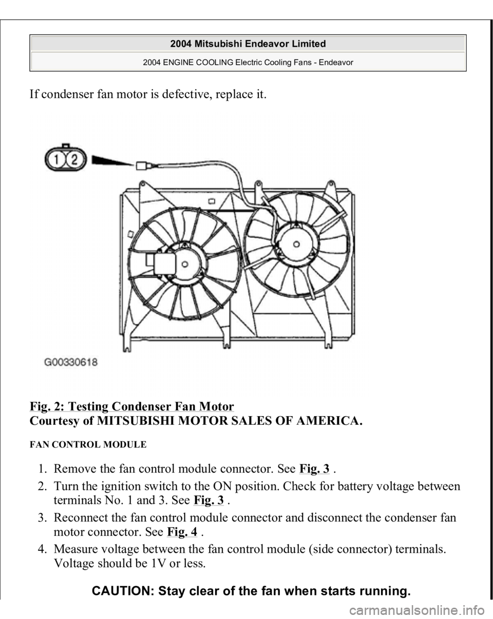
If condenser fan motor is defective, replace it.
Fig. 2: Testing Condenser Fan Motor
Courtesy of MITSUBISHI MOTOR SALES OF AMERICA.
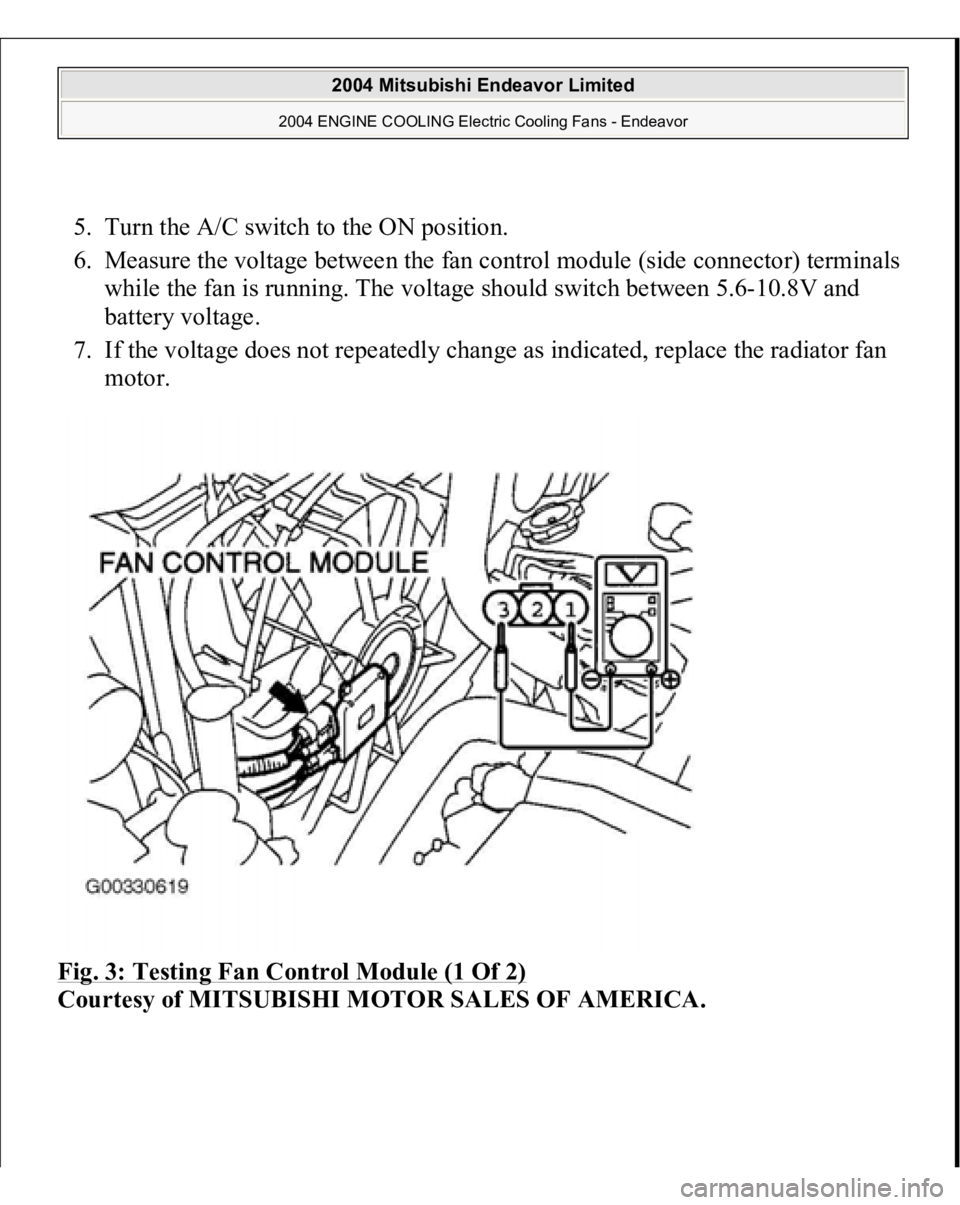
FAN CONTROL MODULE 1. Remove the fan control module connector. See Fig. 3
.
2. Turn the ignition switch to the ON position. Check for battery voltage between
terminals No. 1 and 3. See Fig. 3
.
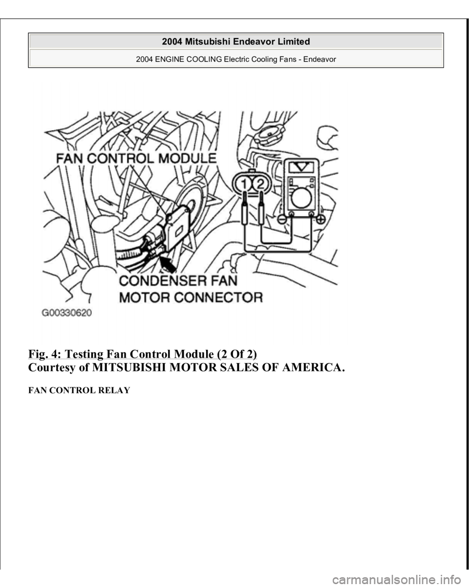
3. Reconnect the fan control module connector and disconnect the condenser fan
motor connector. See Fig. 4
.
4. Measure voltage between the fan control module (side connector) terminals.
Voltage should be 1V or less.
CAUTION: Stay clear of the fan when starts running.
2004 Mitsubishi Endeavor Limited
2004 ENGINE COOLING Electric Cooling Fans - Endeavor
Page 795 of 3870
5. Turn the A/C switch to the ON position.
6. Measure the voltage between the fan control module (side connector) terminals
while the fan is running. The voltage should switch between 5.6-10.8V and
battery voltage.
7. If the voltage does not repeatedly change as indicated, replace the radiator fan
motor.
Fig. 3: Testing Fan Control Module (1 Of 2)
Courtesy of MITSUBISHI MOTOR SALES OF AMERICA.
2004 Mitsubishi Endeavor Limited
2004 ENGINE COOLING Electric Cooling Fans - Endeavor
Page 796 of 3870
Fig. 4: Testing Fan Control Module (2 Of 2)
Courtesy of MITSUBISHI MOTOR SALES OF AMERICA.
FAN CONTROL RELAY
2004 Mitsubishi Endeavor Limited
2004 ENGINE COOLING Electric Cooling Fans - Endeavor
Page 799 of 3870

Technical Descriptio
n
The cause could be a malfunction of the fan control module power supply or
ground circuit. The cause could also be a malfunction of the fan control module or the PCM.
Troubleshooting Hints
Malfunction of fusible link. Malfunction of fan control relay. Malfunction of MFI relay. Malfunction of radiator fan motor. Malfunction of condenser fan motor. Malfunction of fan control module. Malfunction of PCM. Damaged wiring harness or connector.
Diagnosis 1. Disconnect fan control module connector A-23. See Fig. 7
. Measure for
voltage between terminal No. 3 (harness side of the connector) and ground
when ignition switch is turned to the ON position. If battery voltage is not
achieved, go to next step. If battery voltage is achieved, go to step 8 .
2. Check fan control relay. See FAN CONTROL RELAY under
COMPONENTS TESTS. If fan control relay is okay, go to next step. If fan
control relay is not okay, replace it and retest.
3. Check the MFI relay. See MULTI
-PORT FUEL INJECTION (MFI)
RELAY
under COMPONENT TESTS. If MFI relay is okay, go to next step. If
MFI relay is not okay, replace it and retest.
4. Check for harness damage in Black/Yellow wire between fusible link No. 2
and terminal No. 4 of fan control relay connector A-10X. See Fig. 8
. If wire is
okay, go to next step. If wire is damaged, repair or replace as necessary and
retest.
5. Check for harness damage in Blue wire between terminal No. 2 of fan control
rela
y connector
A-10X and terminal No. 3 of fan control module connector A-
2004 Mitsubishi Endeavor Limited
2004 ENGINE COOLING Electric Cooling Fans - Endeavor