Page 800 of 3870
23. See Fig. 7
and Fig.
8 . If wire is okay, go to next step. If wire is damaged,
repair or replace as necessary and retest.
6. Check intermediate connector A-13 for loose, corroded, or damaged terminals,
or terminals pushed back in the connector. See Fig. 9
. If intermediate
connector is okay, go to next step. If connector A-13 is not okay, repair or
replace as necessary and retest.
7. Check for harness damage in Red wire between terminal No. 4 of MFI relay
connector B-16X and terminal No. 1 of fan control relay connector A-10X. See
Fig. 8
and Fig. 10
. If wire is okay, go to next step. If wire is damaged, repair
or replace as necessary and retest.
8. Check for harness damage between terminal No. 3 of fan control relay
connector A-10X and ground. See Fig. 8
. If wire is damaged, repair it and
retest. If wire is okay, retest.
9. Disconnect fan control module connector A-23. See Fig. 7
. Measure resistance
between terminal No. 1 of fan control module connector A-23 (harness side of
connector) and ground. If the resistance is 2 ohms or more, go to next step. If
resistance is less than 2 ohms, go to step 11 .
10. Check the harness wires between terminal No. 1 of fan control module
connector A-23 and ground. If harness wires are okay go to next step. If
harness wires are damaged, repair as necessary and retest.
11. Disconnect all connectors from the PCM. Connect Power Plant ECU Check
Harness (MB991923) between the PCM and the body-side harness connector.
See Fig. 12
. Start the engine and allow it to idle. Measure the output circuit
volta
ge between terminal No. 10 and
ground. See Fig. 12
. If the volta
ge when
NOTE: First inspect terminal No. 7 of intermediate connector
A-13. See Fig. 9
. Then inspect the wires. If intermediate
connector A-13 is damaged, repair or replace as
necessary and retest.
NOTE: Measure the output circuit voltage at terminal No. 10 of
PCM connector B-18 (Green) by using Power Plant ECU
Check Harness (MB991923). See Fig. 11
and Fig. 12
.
2004 Mitsubishi Endeavor Limited
2004 ENGINE COOLING Electric Cooling Fans - Endeavor
Page 801 of 3870
the radiator fan is operating is less than 0.7V, go to next step. If the voltage
when the radiator fan is operating is 0.7V or more, go to step 13 .
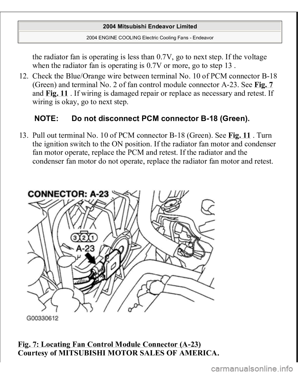
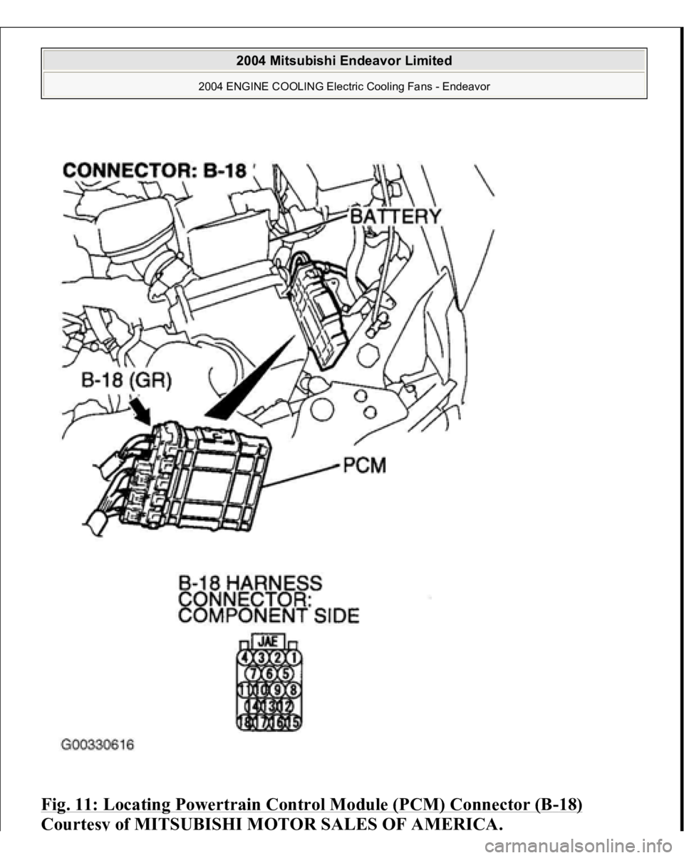
12. Check the Blue/Orange wire between terminal No. 10 of PCM connector B-18
(Green) and terminal No. 2 of fan control module connector A-23. See Fig. 7
and Fig. 11
. If wiring is damaged repair or replace as necessary and retest. If
wiring is okay, go to next step.
13. Pull out terminal No. 10 of PCM connector B-18 (Green). See Fig. 11
. Turn
the ignition switch to the ON position. If the radiator fan motor and condenser
fan motor operate, replace the PCM and retest. If the radiator and the
condenser fan motor do not operate, replace the radiator fan motor and retest.
Fig. 7: Locating Fan Control Module Connector (A
-23)
Courtesy of MITSUBISHI MOTOR SALES OF AMERICA.
NOTE: Do not disconnect PCM connector B-18 (Green).
2004 Mitsubishi Endeavor Limited
2004 ENGINE COOLING Electric Cooling Fans - Endeavor
Page 805 of 3870
Fig. 11: Locating Powertrain Control Module (PCM) Connector (B
-18)
Courtes
y of MITSUBISHI MOTOR SALES OF AMERICA
.
2004 Mitsubishi Endeavor Limited
2004 ENGINE COOLING Electric Cooling Fans - Endeavor
Page 807 of 3870
Fig. 12: Identifying Power Plant ECU Check Harness (MB991923)
Courtesy of MITSUBISHI MOTOR SALES OF AMERICA.
TEST B: RADIATOR FAN & CONDENSER FAN DO NOT CHANGE SPEED OR STOP Technical Description The fan control module has variable control of the radiator fan motor and the
condenser fan motor speeds using signals transmitted from the PCM. Troubleshooting Hints
Malfunction of fan control relay. Malfunction of fan control module. Malfunction of PCM.
Diagnosis 1. Check the fan control relay. See FAN CONTROL RELAY
under
COMPONENT TESTS. If fan control relay is okay, go to next step. If fan
control module is damaged, repair or replace as necessary and retest.
2. Check the harness wire between terminal No. 2 of fan control relay connector
A-10X and terminal No. 3 of fan control module connector A-18. See Fig. 7
and Fig. 8
. If wiring is damaged, repair or replace as necessary and retest. If
wiring is okay, go to next step.
3. Disconnect all the connectors from the PCM. Connect Power Plant ECU Check
Harness (MB991923
) between the PCM and the bod
y-side harness connector.
NOTE: If the engine coolant temperature reaches 230°F (110°C) or
higher, the radiator fan control runs the radiator fan for up
to 5 minutes even after the ignition switch is turned to the
LOCK position. The fan stops its rotation when the engine
coolant temperature decreases to 230°F (110°C) or l ower.
NOTE: Measure the output circuit voltage at terminal No. 10 of
PCM connector B-18 by using Power Plant ECU Check
Harness (MB991923). See Fig. 11
and Fig. 12
.
2004 Mitsubishi Endeavor Limited
2004 ENGINE COOLING Electric Cooling Fans - Endeavor
Page 808 of 3870
See Fig. 12
. Start the engine and allow it to idle. Measure the voltage between
terminal No. 10 of connector B-18 and ground. See Fig. 12
. If the voltage
when the radiator fan is not operating is more than 0.3V, go to next step. If the
voltage when the radiator fan is not operating is less than 0.3V, retest.
4. Check fan control module connector A-23 and PCM connector B-18 for loose,
corroded, or damaged terminals, or terminals pushed back in the connector.
See Fig. 7
and Fig. 11
. If connectors are okay, go to next step. If connectors
are damaged, repair or replace as necessary and retest.
5. Check the harness wire between terminal No. 10 of PCM connector B-18
(Green) and terminal No. 2 of fan control module connector A-23. See Fig. 7
and Fig. 11
. If wiring is damaged repair or replace as necessary and retest. If
wiring is okay, go to next step.
6. Disconnect PCM connector B-18 (Green). See Fig. 11
. Pull out pin No. 10 and
connect it to a body ground. Reconnect PCM connector with pin No. 10 still
removed. Turn the ignition switch to ON position. If the radiator fan motor and
condenser fan motor fan motor stop operating, replace the PCM and retest. If
the radiator fan motor and condenser fan motor do not stop operating, replace
the fan control module and retest.
TEST C: RADIATOR FAN DOES NOT OPERATE Technical Description The cause could be a malfunction of the radiator fan motor or an open circuit
between the fan control module and the radiator fan. Troubleshooting Hints
Malfunction of radiator fan motor.
Diagnosis If radiator fan does not operate, replace the radiator fan.
NOTE: Check terminal No. 7 of intermediate connector A-13,
repair it and then check wiring. See Fig. 9
.
2004 Mitsubishi Endeavor Limited
2004 ENGINE COOLING Electric Cooling Fans - Endeavor
Page 809 of 3870
TEST D: CONDENSER FAN DOES NOT OPERATETechnical Description The cause could be a malfunction of the condenser fan motor or an open circuit
between the fan control module and the radiator fan. Troubleshooting Hints
Malfunction of condenser fan motor. Malfunction of fan control module.
Diagnosis 1. Check the condenser fan motor. See CONDENSER FAN MOTOR
under
COMPONENT TESTS. If condenser fan motor is okay, go to next step. If
radiator fan motor is not okay, replace radiator fan motor and retest.
2. Check the fan control module. See FAN CONTROL MODULE
under
COMPONENT TESTS. If fan control module is okay, retest. If fan control
module is not okay, replace radiator fan motor and retest.
REMOVAL & INSTALLATION RADIATOR FAN Removal & Installation 1. Drain engine coolant.
2. Remove air cleaner.
3. Remove radiator grille.
4. Remove rubber hose. See Fig. 13
.
5. Remove radiator upper hose.
6. Disconnect fan motor connector.
7. Remove shroud assembly.
8. Remove radiator fan.
9. Remove radiator fan motor (integrated with fan control module).
10. Remove condenser fan.
2004 Mitsubishi Endeavor Limited
2004 ENGINE COOLING Electric Cooling Fans - Endeavor
Page 813 of 3870
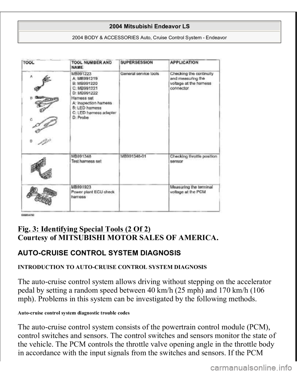
Fig. 3: Identifying Special Tools (2 Of 2)
Courtesy of MITSUBISHI MOTOR SALES OF AMERICA.
AUTO-CRUISE CONTROL SYSTEM DIAGNOSIS INTRODUCTION TO AUTO-CRUISE CONTROL SYSTEM DIAGNOSIS The auto-cruise control system allows driving without stepping on the accelerator
pedal by setting a random speed between 40 km/h (25 mph) and 170 km/h (106
mph). Problems in this system can be investigated by the following methods. Auto-cruise control system diagnostic trouble codes The auto-cruise control system consists of the powertrain control module (PCM),
control switches and sensors. The control switches and sensors monitor the state of
the vehicle. The PCM controls the throttle valve opening angle in the throttle body
in accordance with the in
put si
gnals from the switches and sensors. If the PCM
2004 Mitsubishi Endeavor LS
2004 BODY & ACCESSORIES Auto, Cruise Control System - Endeavor
Page 835 of 3870
2. Turn the ignition switch to the "ON" position.
3. Set scan tool MB991958 to data reading mode for auto-cruise control
system.
Item 03: Resume Switch.
When "ACC/RES" switch is at the "ON" position, the display on
scan tool MB991958 should be "ON". When "ACC/RES" switch is at the "OFF" position, the display
on scan tool MB991958 should be "OFF".
4. Turn the ignition switch to the "LOCK" (OFF) position.
5. Disconnect scan tool MB991958.
Q: Is the switch operating properly?
YES : Go to Step 17 .
NO : Go to Step 3.
STEP 3. Measure the power supply voltage at auto-cruise control switch
connector C-302 by backprobing.
1. Remove the air bag module (driver's side). (Refer to GROUP 52B, Air
Bag Modules and Clock Spring P.52B-567).
2. Connect the negative (-) battery cable.
3. Do not disconnect auto-cruise control switch connector C-302.
2004 Mitsubishi Endeavor LS
2004 BODY & ACCESSORIES Auto, Cruise Control System - Endeavor